1
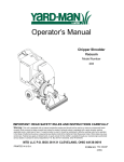
Spicer Single Drive Axles
®
Service Manual
Spicer® Single Drive Axles
AXSM-0043
September 2007
The description and specifications contained in this service
publication are current at the time of printing.
Dana Corporation reserves the right to discontinue or modify its
models and/or procedures and to change specifications at any time
without notice.
I
Any reference to brand name in this publication is made as an
example of the types of tools and materials recommended for use
and should not be considered an endorsement. Equivalents may
be used.
IMPORTANT NOTICE
This symbol is used throughout this
manual to call attention to procedures
where carelessness or failure to follow
specific instructions may result in personal
injury and/or component damage,
Departure from the instructions, choice of
tools, materials and recommended parts
mentioned in this publication may jeopardize the personal safety of the service
technician or vehicle operator,
WARNINGS: FAILURE TO FOLLOW
INDICATED PROCEDURES CREATES A HIGH
RISK OF PERSONAL INJURY TO THE
SERVICING TECHNICIAN,
Caution: Failure to follow indicated
procedures may cause component damage
or malfunction.
Note: Additional service information not
covered in the service procedures.
Tip: Helpful removal and installation
procedures to aid in the service of this unit.
Always use genuine Spicer replacement parts.
1
Spicer Axle Service and Maintenance Instructions
Single Reduction Axles
Introduction
Dana Corporation presents this publication to aid in maintenance and overhaul of Spicer single
reduction, single drive axles.
The axle models contained in this manual are of common design. Physical variances occur in the axle housing, differential
gearing and axle shafts because of varying load carrying capacities (see chart on page 4). For other variables refer to the
exploded view on page 5.
Instructions contained herein are applicable to all axle models, unless specified otherwise.
For brake information and axle mounting or suspension systems, refer to pertinent truck manufacturerÕs literature.
Axle models covered in this publication:
13101
15101,15131
16121,16131
17101,17103,17121,17123,17131,17133
18101.18121.18123
19101,19121
20101,20121
21121,21131,21133
22121,22123,22131,22133
23121,23123,23133
26121
30127
Contents
Notice
Introduction
Axle and Carrier Identification
Axle Housing Identification
Description and Operation
Differential Carrier Assembly
Lubrication
Changing Lube
Wheel End Lubrication
Cleaning, Inspection, Replacement
Adjustments
Wheel Bearing Adjustment
Differential Carrier Adjustment
Final Pinion Bearing reload Test
Adjust Pinion Bearing Preload for Axles with
"Slip-fit" Outer Pinion Bearings
Differential Bearing Preload and Ring Gear
Remove Differential Carrier Assembly
Disassemble Differential Carrier
Disassemble Drive Pinion
Disassemble Wheel Differential
Assemble Wheel Differential
Differential Carrier Overhaul
Assemble Drive Pinion
Install Drive Pinion
Install Differential and Ring Gear Assembly
Adjust Differential Bearing Preload
Price $3.50
2
Axle and Carrier Assembly Model Identification
Differential carrier identification is either stamped on the carrier itself or
on a metal tag affixed to the carrier, Location on the carrier is the same.
Metal Tag on
Differential
Carrier
Axle Specification Number
.
The complete axle is identified by the specification
number stamped on the rear right-hand side of the
axle housing. This number identifies all component
parts of the axle as built by Spicer, including special
OEM requirements such as yoke or flange.
In addition, some axles
may include a metal identification tag (see
illustration).
Ring Gear and Pinion Identification
Ring Gear and Drive Pinion
are matched parts and must be
replaced in sets. Check the appropriate Spicer Axle parts book
for part numbers and ordering
instructions.
To aid in identifying gear sets,
both parts are stamped with such
information as number of pinion
and ring gear teeth, individual part
number and matched set number
(refer to adjacent drawing).
3
3PICER Single Reduction Axles
¨
Description and Operation
Spicer single reduction axles are
of the full-floating type with a
single-speed differential assembly.
The gearing is spiral bevel design
with drive pinion positioned at
centerline of the ring gear.
Drive pinion is straddle-mounted
on two tapered roller bearings and
a straight roller type pilot bearing.
The differential assembly is mounted on two tapered roller bearings.
Power flow is through the drive
pinion and ring gear, and a 4 side
pinion, 2 side gear type differential
to the axle shafts and wheels.
The majority of variances in axle
models included in this manual is
in ring gear size and capacities
(see chart below). For detailed
variances refer to exploded view
of differential (page 5).
4
Differential Carrier Assembly
I
Flat Washer not used on 13, 15, 16 Series.
Dowel Bushing not used on 13, 15, 16, 17, 18, 21 Series
Lockwire not used on 17, 18, 21, 22, 23, 26 (late 30 Series.
Oil Trough & Capscrew not used on 13, 15, 16, 17, 18, 21, 22, 23, 26 (late), 30 Series.
Spacer Washer not used on 13, 15, 16, 17, 18, 21, 22 Series.
Dowel Pin not used on 17, 18, 19, 20, 21, 22, 23,26, 30 Series.
Flat Washer not used on 15130, 16130, 17130, 19121, 20121,23,26,30 Series.
2-Speed Differential Carrier is used on 22 Series. Axles so 17“ gearing will fit.
Yoke Spacer used only if retrofitting 17 Series Axles with current gear/ pinion sets built
with 55200C Inner Pinion Bearings. Reference Instruction Sheet 129277.
5
Single Reduction Single Drive Axles
Lubrication
The ability of a drive axle to deliver quiet, trouble-free operation
over a period of years is largely dependent upon the use of good
quality gear lubricant incorrect quantity. The most satisfactory
results can be obtained by following the directions contained in this
manual.
The following lubrication instructions represent the most current
recommendations from the Axle & Brake Division of Dana
Corporation.
Approved Lubricants
General-Gear lubrications acceptable under military specification
(MILSPEC) MIL-L-2105D (Lubricating Oils, Gear, Multipurpose)
preapproved for use in Spicer Drive Axles. The MIL-L-2105D
specification defines performance and viscosity requirements for
multigrade oils. It supersedes both MIL-L-2105B, MIL-L-2105C
and cold weather specification Ml L-L-l 0324A. This specification
applies to both petroleum-based and synthetic based gear lubricants if they appear on the most current “Qualified Products List”
(QPL-2105) for MIL-L-2105D.
Note: The use of separate oil additives and/or friction modifiers
are not approved in Spicer Drive Axles.
Synthetic based-Synthetic-based gear lubricants exhibit superior
thermal and oxidation stability, and generally degrade at a lower
rate when compared to petroleum-based lubricants. The performance characteristics of these lubricants include extended change
intervals, improved fuel economy, better extreme temperature
operation, reduced wear and cleaner component appearance. The
family of Spicer gear lubricants represents a premium
quality synthetic lube which fully meets or exceeds the requirements of MIL-L-2105D. These products, available in both 75W-90
and 80W-140, have demonstrated superior performance in
comparison to others qualified under the MINPEC, as demonstrated by extensive laboratory and field testing. For a complete list
of Spicer approved synthetic lubricants contact your local
Spicer representative. See back cover of this manual for appropriate phone number.
Makeup Lube-Maximum amount of non-synthetic makeup lube
is 100/..
6
Viscosity/Ambient Temperature Recommendations-The following
chart lists the various SAE Grades covered by MIL-L-2105D and
the associated ambient temperature range from each. Those SAE
grades shown with an asterisk (*) are available in the Spicer
family of synthetic gear lubricants,
The lowest ambient temperatures covered by this chart are -40oF
and -40oC. Lubrication recommendations for those applications
which consistently operate below this temperature range, must be
obtained through the Dana Corporation by contacting your local
Spicer representative.
I
Grade
75W
Ambient Temperature Range
- 4 0o F to -15°F (-40o C to -26o C )
75W-80
- 4 0o F to 80o F (-40o C to 27o C )
75W-90*
- 4 0o F to 100o F (-40o C to 38o C )
75W-140
-40°F and above (-40oC and above)
80W-90
-15oF to 100oF (-26°C to 38oC )
80W-140*
-15°F and above (-26°C and above)
85W-140
1O°F and above (-12°C and above)
Single Reduction Single Drive Axles
Lube Change Intervals
This product combines the latest manufacturing and part washing
technology. When filled with an Spicer approved synthetic
lubricant at the factory, the initial drain is not required.
Change the lubricant within the first 5,000 miles of operation
when not using a Spicer approved synthetic lubricant in
either a new axle or after a carrier head replacement. Base
subsequent lubricant changes on a combination of the following
chart and user assessment of the application and operating
environment.
Severe Service Lubrication Change Intervals-Severe service
applications are those where the vehicle consistently operates
at or near its maximum GCW or GVW ratings, dusty or wet
environments, or consistent operation on grades greater than 8%.
For these applications, the ON/OFF HIGHWAY portion of the chart
should be used. Typical applications are construction, logging,
mining and refuse removal.
Note: Remove metallic particles from the magnetic filler plug and
drain plugs. Clean or replace the breather at each lubricant change.
Guidelines - Lube Change Intervals for Drive Axles
Lubricant Type
Petroleum
Based
Spicer- Approved
Maximum Change
Interval
100,000
250,000
Maximum Change
Interval
On/Off Highway Severe
Service Miles
Yearly
40,000
3 Years
100,000
Maximum Change
Interval
Yearly
Yearly
Synthetic
7
Checking Lube Level
Remove the filler hole plug located
in the axle housing cover. Lube
should be level with the bottom of
this hole.
IMPORTANT: Lube level close
enough to the hole to be seen or
touched is not sufficient, It must
be level with the hole.
NOTE: When checking lube level,
also check and clean housing
breathers.
Ñ
Changing Lube
Draining
Drain when the lube is at normal operating temperature. It will run freely
and minimize the time necessary to fully drain the axle.
Unscrew the magnetic drain plug on the underside of the axle housing
bowl section and allow the lube to drain into a suitable container. Inspect
drain plug for large quantities of metal particles. After initial oil change,
these are signs of damage or extreme wear in the axle, and inspection of
the entire unit may be warranted. Clean the drain plug and replace it after
the lube has drained completely.
Filling
Remove the filler hole plug from
the center of the axle housing
cover and fill the axle with
approved lubricant until level
with the bottom of the hole.
NOTE: Lube fill capacities in the
adjacent chart are good guidelines
but will vary somewhat on the
basis of the angle the axle is
installed in a particular chassis.
Always use the filler hole as the
final reference. If lube is level with
the bottom of the hole, the axle is
properly filled.
Axles installed at angles exceeding
6¡ or operated regularly in areas
requiring negotiation of grades
exceeding 12% may require standpipes to allow proper fill levels.
For specific recommendations,
contact your local 6SLFHU representative. See back cover of this
manual for phone numbers.
8
Lube Capacities*
DO NOT OVERFILL AXLES
Axle Series
13,15 . . . . . . . . . . . .
16 . . . . . . . . . . . . . . .
17,18 . . . . . . . . . . . .
19,20 . . . . . . . . . . . .
21,22 . . . . . . . . . . . .
23,26,30 . . . . . . . .
Vendor Housing
6SLFHU Housing
(Round Arm)
(Rectangular Arm)
Pints (liters)
Pints (liters)
19 ( 9)
23 (11)
24 (11)
33 (16)
29 (14)
37 (18)
38 (18)
37 (18)
34 (16)
41 (19)
*Capacities listed are approximate. The amount of lubricant will vary with angle of
axle as installed in vehicle chassis. Figures do not apply to housings not designed
or manufactured by 6SLFHU.
I
Single Reduction Single Drive Axles
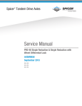
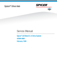
Wheel End Lubrication
Wheel ends with an oil fill hole
Following any servicing of wheel ends, the wheel hub cavities and
bearings must be lubricated to prevent failure.
Caution: Make sure the wheel ends are well lubricated
with the same axle lubricant used in the axle sump, Do
not pack the bearings with grease before installation as
grease will prevent the proper circulation of axle
lubricant and may cause wheel seal failure.
1. Rotate the wheel end hub until the oil fill hole is up.
2. Remove the oil fill plug.
3. Pour 1 pint of axle sump lubricant into each hub through the
wheel end fill hole.
4. Install oil fill plug and tighten to specified torque.
6SLFHU axles may be equipped with either of two wheel end designs:
Wheel ends with an oil fill hole
Wheel ends without an oil fill hole
See Figure 1 for cutaway views of the two different designs.
Figure 1 Cutaway Views of Typical Wheel End Assemblies
9
Single Reduction Single Drive Axles
Wheel ends without an oil fill hole
1. With axle level and wheel ends assembled, add lubricant
through filler hole in axle housing cover until fluid is level with
the bottom of filler hole.
2. Raise the left side of the axle 6 inches or more, Hold axle in
this position for one minute.
3, Lower the left side.
4. Raise the right side of the axle 6 inches or more. Hold axle in
this position for one minute.
5. Lower the right side.
10
6. With axle on a level surface, add additional lubricant through
housing cover oil filler hole to raise lube to required level.
Note: Axles without wheel end fill holes will require approximately
2.5 additional pints of lubricant to bring the lube level even with the
bottom of the fill hole.
Tip: The use of ramps or making a full lock figure eight turning
maneuver at low speed will guarantee the wheel end is charged
with lube. Refill axle to proper lube level, (Follow procedure on
page 8).
Cleaning, Inspection, Replacement
As the drive axle is disassembled, set all parts aside for thorough
cleaning and inspection. Careful inspection will help determine whether
parts should be reused. In many cases, the causes of premature wear or
drive axle failure will also be revealed.
Cleaning
The differential carrier assembly may be steam-cleaned while mounted in
the housing as long as all openings are tightly plugged. Once removed
from its housing, do not steam clean differential carrier or any
components. Steam cleaning at this time could allow water to be trapped
in cored passages, leading to rust, lubricant contamination, and
premature component wear. The only proper way to clean the assembly
is to disassemble it completely. Other methods will not be effective
except as preparatory steps in the process. Wash steel parts with ground
or polished surfaces in solvent. There are many suitable commercial
solvents available. Kerosene and diesel fuel are acceptable.
WARNING: GASOLINE IS NOT AN ACCEPTABLE SOLVENT BECAUSE
OF ITS EXTREME COMBUSTIBILITY. IT IS UNSAFE IN THE
WORKSHOP ENVIRONMENT.
Wash castings or other rough parts in solvent or clean in hot solution
tanks using mild alkali solutions. If a hot solution tank is used, make
sure parts are heated thoroughly, before rinsing.
Rinse thoroughly to remove all traces of the cleaning solution. Dry parts
immediately with clean rags.
Lightly oil parts if they are to be reused immediately. Otherwise, coat
with oil and wrap in corrosion-resistant paper. Store parts in a clean, dry
place.
Inspection
Inspect steel parts for notches, visible steps or grooves created by wear.
Look for pitting or cracking along gear contact lines. Scuffing,
deformation or discoloration are signs of excessive heat in the axle,
usually related to low lubricant levels or improper lubrication practices.
Before reusing a gear set, inspect teeth for signs of excessive wear.
Check tooth contact pattern for evidence of incorrect adjustment (see
Adjustment Section for correct pattern).
Inspect machined surfaces of cast or malleable parts. They must be free
of cracks, scoring, and wear. Look for elongation of drilled holes, wear
on surfaces machined for bearing fits and nicks or burrs in mating
surfaces.
Inspect fasteners for rounded heads, bends, cracks or damaged threads.
The axle housing should be examined for cracks or leaks. Also look for
loose studs or cross-threaded holes.
Inspect machined surfaces for nicks and burrs.
11
Adjustments
Wheel Bearing Adjustment
Wheel bearings should be adjusted at regular intervals
using the following procedure:
PREPARATION: Provide means to capture lubricant that
will escape when axle shafts are removed. Remove axle
shafts. Jack the wheel to be adjusted clear of the
ground.
After securely blocking the vehicle to prevent rolling,
release the parking brake, allowing the wheel to rotate
freely.
WARNING: Never work under a
vehicle supported only by a jack.
Insure that the vehicle will not roll
before releasing brakes.
1. Remove outer adjusting nut and doweled (or tanged)
washer.
2. Visually inspect spindle for damage or wear. Inspect
the nut and spindle threads for damage. Make certain
that the nut turns without binding by cleaning the threads
and applying a light coat of oil prior to adjusting the
wheel bearings. Inspect tanged washer (if used).
Replace washer if tangs are broken or badly misshaped.
3. Torque inner nut to 200 Ibs.-ft. (272 N•m) while
rotating the wheel. Loosen the nut one full turn. Retorque to 50 Ibs.-ft. (68 N•m). Back off nut exactly 1/4 of
a turn.
4. Install doweled (or tanged) washer. If the dowel pin
and washer (or washer tang and nut flat) are not aligned,
remove washer, turn it over and reinstall. For further
alignment, loosen the inner nut slightly.
5. Install outer nut and torque as follows:
Dowel type washer lock -300 Ibs. -ft. (408 N•m)
Tang type washer lock -250 Ibs. -ft. (229 N•m)
●
●
This adjustment procedure should allow wheel to turn
freely with 0.001’’-0.005” (0.025mm to 0.250 mm) endplay.
NOTE: The end-play should be measured using a dial
indicator with a 0.001” resolution. With the tires and
wheels on the hub, rock the wheel end back and fourth
before making the end-play measurement. This will
result in a more accurate reading.
IMPORTANT Never tighten the inner nut for alignment.
This will preload the bearing and cause premature
failure.
12
6. If using the tanged washer type lock, secure adjusting
nuts by bending one wheel nut washer tang over each nut.
Bend tang over the closest flat perpendicular to the tang
(see Illustration).
7. Install axle shaft gasket& axle shaft. Refill axle to
proper lube level. (Follow procedure on page 8).
Adjustments
Differential/ Carrier Adjustments
Adjustments help provide optimum axle life and performance by correctly
positioning bearings and gears under load.
6SLFHU single drive axles require two types of adjustments: Bearings must be
preloaded and ring gear tooth contact must be set.
Bearing Preload — Both pinion and differential bearings Adjust Pinion Bearing Preload — Most 6SLFHU axles
require preloading. The adjustment procedures seat
will be found with a “slip-fit” outer pinion bearing,
but recent design changes provide a “press-fit” on
these bearings in their cups for good support and free
rotation under load. The pinion pilot bearing does not
this bearing (in some axle models). Procedures for
require a preload adjustment.
adjusting both types of pinion bearing design are
contained in this section.
Adjust Pinion Bearing Preload for Axles With
"Press-fit” Outer Pinion Bearings
Trial Build-up
1. Assemble the pinion bearing
cage, bearings and spacer (without drive pinion or oil seal).
NOTE: During assembly procedure, center bearing spacer
(and spacer washer when used)
between the two bearing cones.
2. With the bearings well lubricated, place the assembly in the
press. Position a sleeve or spacer
so that load is applied directly to
the back face of the outer bearing
cone.
3. Apply press load to the
assembly and check rolling
torque. Wrap soft wire around the
bearing cage, attach spring scale
and pull. Preload is correct when
torque required to rotate the
pinion bearing cage is from 1020 inch pounds. This specification is translated into spring scale
readings in the chart below.
4. If necessary, Adjust Pinion
Bearing Preload by changing the
pinion bearing spacer. A thicker
spacer will decrease preload. A
thinner spacer will increase
preload.
Assemble these Parts for Trial Build-up.
Cage in Press
to Check Bearing
Preload.
Spring Scale Reading
(without pinion seal)
(for 10-20 m-lbs. torque)
(1.1-2.3 N•m)
Specifications for Pinion Bearing
Trial Build-up Preload Test
(“Press-fit” Outer Pinion Bearings)
Axle Series
16
17/1 8/21
22
19/20/23/26/30
Nominal Bearing
Spacer Thickness
in.
0.528
0.638
0.638
0.638
0.185
mm.
13.41
16.21
16.21
16.21
4.70
IMPORTANT: Once correct bearing preload has been established,
note the spacer size used. Select a
spacer 0.001” larger for use in the
final pinion bearing cage assembly.
The larger spacer compensates
for slight “growth” in the bearings which occurs when they are
pressed on the pinion shank. The
trial build-up will result in proper
pinion bearing preload in three
of four cases.
IMPORTANT: Do not assume that
all assemblies will retain proper
preload once bearings are pressed
on pinion shank. FINAL PRELOAD
TEST MUST BE MADE IN EVERY
CASE.
Press Loads
Tons
Metric Tons
12-13
11-12
14-15
14-15
19-20
11-12
10-11
13-14
13-14
17-18
lb.s
kgs.
5-9
5-9
4-8
4-7
3-7
2.3-4.1
2.3-4.1
1.8-3.6
1.8-3.2
1.4-3.2
13
Final Pinion Bearing Preload Test
1. Assemble the complete pinion bearing cage unit as recommended
in the assembly section of this manual (Page 25).
2. Apply clamp load to the pinion bearing cage assembly. Either install
the yoke and torque the pinion nut to specifications or use a press to
simulate nut torque (see chart below).
Vise Method - If the yoke and nut are used, mount the assembly in a
vise, clamping yoke firmly.
Press Method - If a press is used, position a sleeve or spacer so that
load is applied directly to the back-face of the outer bearing cone.
3. Measure Pinion Bearing Preload - Use a spring scale to test the
assembly rolling torque. To use the spring scale, wrap soft wire around
the bearing cage, attach the scale and pull. Preload is correct when
torque required to rotate the pinion bearing cage is from 15 to 35 inch
pounds. This specification is translated into spring scale readings in the
chart below.
4. Adjust Pinion Bearing Preload - If necessary, adjust pinion bearing
preload. Disassemble the pinion bearing cage as recommended in this
manual and change the pinion bearing spacer. A thicker spacer will
decrease preload. A thinner spacer will increase preload.
IMPORTANT: Use the correctly sized spacer. Do not use shim stock or
grind spacers. These practices can lead to loss of bearing preload and
gear or bearing failure.
Measuring Bearing Preload with
Pinion in Vise.
Measuring Bearing Preload with
Pinion in Press.
Spring Scale Reading
(without pinion seal)
(for 15-35 in-lbs. torque)
(1.7-4 N.m)
Specifications for Final Pinion
Bearing Preload Test
("Press-fit" Outer Pinion Bearings)
Axle Series
13/15/16
17/18+
17/18/19/20/21/22Ê
19/20/23/26/30ˆ
Nut Torque
Ft-lbs.
360-440
480-600
560-700
840-1020
Press Loads
N.m
Tons
12-13
488-596
650-813
14-15
759-949
14-15
1139-1383
19-20
Metric Tons
11-12
13-14
13-14
17-18
+1 1/4-12 Pinion Nut Ê1 1/2-18 Pinion Nut ˆ1 3/4-12 Pinion N ut, *15130 & 16130 Models only use metric nut
M30 X 1.5, 17130 models use metric nut M36 X 1.5,23130 models use metric nut M \42 X 1.5
14
Ib.s
7-16
6-14
6-13
5-12
kgs.
3.2-7.3
2.7-6.4
2.7-5.9
2.3-5.4
Adjustments
Adjust Pinion Bearing Preload for Axles with
"Slip-fit" Outer Pinion Bearings
1. Lubricate bearings and assemble the drive pinion, bearings, and
pinion bearing cage as recommended in the assembly section of this
manual (Page 25). Use the pinion bearing spacer removed from the axle
during disassembly. If the original spacer cannot be used, install the
nominal spacer recommended in the adjacent chart.
NOTE: Bearing spacer washer is not used on 13, 15, 16, 17, 18, 21, 22
Series axles.
2. Apply clamp load to the pinion bearings. Install the yoke and torque the
nut to specification or use a press to simulate nut torque by applying
pressure to the assembly (see chart below).
Vise Method - If the yoke and nut are used, mount the assembly in a vise,
clamping yoke firmly.
Press Method - If a press is used, position a sleeve or spacer so that
load is applied directly to the back-face of outer pinion bearing.
3. Measure Pinion Bearing Preload - Use a spring scale to test the
assembly rolling torque. To use the spring scale, wrap a soft wire around
the bearing cage, attach the scale and pull. Preload is correct when
torque required to rotate the pinion bearing cage is from 15 to 35 inch
pounds. This specification is translated into spring scale readings in the
chart below.
4. Adjust Pinion Bearing Preload - If necessary, adjust pinion bearing
preload. Disassemble the pinion bearing cage as recommended in this
manual and change the pinion bearing spacer. A thicker spacer will
decrease preload. A thinner spacer will increase preload.
IMPORTANT: Use the correctly sized spacer. Do not use shim stock or
grind spacers. These practices can lead to loss of bearing preload and
gear or bearing failure.
Measuring Bearing Preload with
Pinion in Vise.
Nut Torque
Ft-lbs.
360-440
480-600
560-700
840-1020
Spacer Thickness
Axle Model
13/15 . . . . . . . . . . . . . . .
16 . . . . . . . . . . . . . . . . .
17/18/21/22 . . . . . . . .
19/20/23/26/30 . . . . . . . .
in.
mm
0.528 13 .41
0.638 16 .21
0.638 16.21
0.185 4.70
Measuring Bearing Preload with
Pinion in Press.
Specifications for Pinion
Bearing Preload Test
("Slip-fit" Out er Pinion Bearings)
Axle Series
13/15/16*
17*/18+
17*/18/19/20/21/22Ê
19/20/23*/26/30ˆ
Nominal Pinion
Bearing Spacers
Press Loads
N.m
Tons
488-596
12-13
650-813
14-15
759-949
14-15
1139-1383
19-20
Spring Scale Reading
(without pinion seal)
(for 15-35 m-lbs. torque)
(1.7-4 N.m)
Metric Tons
11-12
13-14
13-14
17-18
Ib.s
7-16
6-14
6-13
5-12
k S.
3.2-7.3
2.7-6.4
2.7-5.9
2.3-5.4
+1 1/4-12 Pinion Nut Ê1 1/2-18 Pinion Nut ˆ1 3/4-12 Pinion N ut, *15130 & 16130 Models only use metric nut
M30 X 1.5, 17130 models use metric nut M36 X 1,5,23130 models use metric nut M42 X 1.5
15
Differential Bearing Preload and Ring Gear
Backlash Adjustment
Correct differential bearing preload insures proper location of these
bearings under load and helps position the ring gear for proper gear
tooth contact.
(Follow procedures in numerical sequence.)
Adjust Diff. Bearing Preload
1. Lubricate differential bearings.
IMPORTANT: When installing
bearing caps and adjuster, exert
care not to cross threads.
2. Install adjusters and bearing
caps. Tighten bearing cap screws
finger-tight. If this is difficult,
use a hand wrench.
4. Tighten the bearing adjuster
on the back-face side of the ring
gear until there is no backlash.
This can be tested by facing the
ring gear teeth and pushing the
gear away from the body while
gently rocking the gear from side
to side. There should be no free
movement.
Rotate the ring gear and check
for any point where the gear may
bind. If such a point exists,
loosen and retighten the back
side adjuster. Make all further
adjustments from the point of
tightest mesh.
Adjust Ring Gear Backlash
To add backlash: Loosen the
adjuster on the teeth side of the ring
gear several notches. Loosen the
opposite adjuster one notch.
Return to adjuster on teeth side of
the ring gear and tighten adjuster
until it contacts the bearing cup.
Continue tightening the same adjuster 2 or 3 notches. Recheck
backlash.
16
3. Loosen the bearing adjuster
on the same side as the ring gear
teeth until its first thread is
visible.
/
5. At teeth side of ring gear,
tighten adjuster until it contacts
the bearing cup. Continue tightening adjuster two or three notches
and this will preload bearings and
provide backlash.
6. Measure backlash with a dial indicator.
USED GEARING — Reset to backlash recorded before disassembly.
NEW GEARING — Backlash should be between 0.006” and 0.016”
on most models. Axles with 17” or 18” ring gears require
0.008” to 0.018” backlash.
To remove backlash: Loosen the
adjuster on the teeth side of the ring
gear several notches. Tighten the
opposite adjuster one notch.
Return to adjuster on teeth side of
ring gear and tighten adjuster until it
contacts the bearing cup. Continue
tightening the same adjuster 2 or 3
notches. Recheck backlash.
Moving adjuster one notch is the
movement of the lead edge of one
adjuster lug to the lead edge of the
next lug past a preselected point.
Adjustments
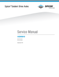
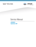
Ring Gear and Pinion Tooth Contact
Check Tooth Contact Pattern (NEW GEAR)
Paint twelve ring gear teeth with marking compound
and roll the gear to obtain a contact pattern. The correct
pattern is well-centered on the ring gear tooth with
lengthwise contact clear of the toe. The length of the
pattern in an unloaded condition is approximately onehalf to two-thirds of the ring gear tooth in most models
and ratios.
RING GEAR TOOTH NOMENCLATURE
CORRECT PATTERN (NEW GEARING)
• pattern should be clear of tooth toe.
Check Tooth Contact Pattern (USED GEAR)
Used gearing will not usually display the square,
even contact pattern found in new gear sets. The
gear will normally have a “pocket” at the toe-end
of the gear tooth which tails into a contact line
along the root of tooth. The more use a gear has
had, the more the line becomes the dominant
characteristic of the pattern.
Adjust used gear sets to display the same contact
pattern observed before disassembly. A correct
pattern is clear of the toe and centers evenly along
the face width between the top land and root.
Otherwise, the length and shape of the pattern are
highly variable and is considered acceptable as
long as it does not run off the tooth at any point.
CORRECT PATTERN (USED GEARING)
17
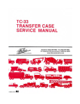
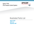
Adjust Tooth Contact Pattern
If necessary, adjust the contact pattern by moving the ring gear and
drive pinion. Ring gear position controls the backlash. This adjustment
moves the contact pattern along the face width of the gear tooth. Pinion
position is determined by the size of the pinion bearing cage shim pack. It
controls contact on the tooth depth of the gear tooth.
These adjustments are interrelated. As a result, they must be considered together even though the pattern is altered by two distinct
operations. When making adjustments, first adjust the pinion, then the
backlash. Continue this sequence until the pattern is satisfactory.
Adjust Pinion Position
If the gear pattern shows incorrect tooth depth contact, change drive
pinion position by altering the shim pack. Used gears should achieve
proper contact with the same shims removed from the axle at disassembly.
INCORRECT PATTERN
●
Pattern too close to tooth top land and off center.
If the pattern is too close to the top land of the
gear tooth, remove pinion shims.
INCORRECT PATTERN
Pattern too close or off tooth root.
If the pattern is too close to the root of the gear
tooth, add pinion shims.
NOTE: Check ring gear backlash after each shim change and adjust if necessary to maintain the
.006¡ to .016¡ specifications. Axles with 17¡ or 18¡ ring gears require .008¡ to .018¡ backlash.
Adjust Backlash
If the gear pattern shows incorrect face width contact, change backlash.
INCORRECT PATTERN
●
Pattern too close to edge of tooth toe.
With the pattern concentrated at the toe (too far
down the tooth), add backlash by loosening the
bearing adjuster on the teeth side of ring gear several notches. Loosen the opposite adjuster one notch.
Return to adjuster on teeth side of ring gear and
tighten adjuster until it contacts the bearing cup.
Continue tightening the same adjuster 2 or 3
notches. Recheck backlash.
18
INCORRECT PATTERN
●
Pattern too far along tooth toward tooth heel.
If the pattern is concentrated at the heel (too
far up the tooth), remove backlash by Ioosening the
bearing adjuster on the teeth side of ring gear several notches. Tighten the opposite adjuster one notch.
Return to adjuster on teeth side of ring gear and
tighten adjuster until it contacts the bearing cup.
Continue tightening the same adjuster 2 or 3
notches. Recheck backlash.
Fastener Tightening Specifications
Axle Series: 13, 15, 16, 17, 18, 19, 20, 21, 22, 23, 26, 30
Specifications are for all axle models unless specified otherwise.
Correct tightening torque values are extremely important to assure
long 6SLFHU Axle life and dependable performance. Under-tightening
of attaching parts is just as harmful as over-tightening.
● Exact compliance with recommended torque values will assure the
best resuIts.
● The data includes fastener size, grade and torque tightening values.
Axle models are included to pinpoint identification of fasteners for
your particular axle.
● TO determine bolt or cap screw grade, check for designation stamped
on bolt head (see illustration).
●
Bolt head markings
for grade identification
Grade 5
Grade 8
19
Differential Carrier Replacement
Remove Differential Carrier Assembly from Axle Housing
Install Differential Carrier Assembly
IMPORTANT: Before installing
carrier assembly, inspect and
thoroughly clean interior of
axle housing.
NOTE: Use silicone rubber gasket
compound on axle housing mating
surface as shown in the illustration.
Gasket compound will set in 20 minutes. Install carrier before compound
sets or reapply.
1. Install differential carrier
assembly in axle housing. Install
stud nuts, cap screws and lockwashers. Tighten to correct torque
(see chart).
4. Fill axle with correct lube (see
Lubrication Section).
2. Install axle shafts and stud nuts.
(If used, also install lockwashers
and taper dowels. )
3. Connect driveline.
Torque Chart
Differential Carrier CAP SCREW
S i z e G r a d e F t.-l b s . N m
Axle Series
48-56
65-75
13,15 . . . . ..7/16-14 (5)
75-85 101-115
16, . . . . . . . . 1/2-13 (5)
17,18,19,
20,21,22,
160-176 217-239
23,26,30
5/8-11 (5)
5/8-18 (8)
200-230 271-312
N U T
Axle Housing Gasket
Compound Pattern.
20
17,1819,20,
21,22,23,
26,30
5/8-18
220-240 298-325
IMPORTANT: When axle has been
disassembled or housing, gears,
axle shafts or wheel equipment
replaced, check axle assembly for
proper differential action before
operating vehicle. Wheels must
rotate freely and independently.
Differential Carrier Overhaul
Disassemble Differential Carrier
NOTE: If gear set is to be reused, check tooth contact pattern and ring
gear backlash before disassembling differential carrier. Best results are
obtained when established wear patterns are maintained in used
gearing. Omit this step if the gear set is to be replaced.
1. Mount Differential Carrier
Assembly in repair stand. Loosen
but do not remove pinion nut.
2. Punch mark differential bearing caps. If reusing gear set, also
punch mark bearing adjusters for
reference during assembly.
4. Using a chain hoist, lift ring
gear and differential assembly out
of carrier.
5. Remove pinion bearing cage
cap screws, then drive pinion,
cage and yoke assembly out of
carrier.
3. Cut lockwire. Remove cap
screws, flat washers and bearing
caps.
IMPORTANT: Do not allow pinion
to drop on hard surface. Remove
shim pack.
IMPORTANT: If gear set is to
be reused, keep pinion bearing
cage shim pack intact for use in
reassembly. If the original shims
cannot be reused, record the
number and size of shims in the
pack.
21
Disassemble Drive Pinion
NOTE: drive
axles may be equipped
with either "slip-fit" or
"press-fit" outer pinion
bearings. Procedures
are contained in this
section for disassembly
of both types.
NOTE: Lubricate parts
with gear lube during
reassembly.
IMPORTANT: During the follow-
ing yoke removal procedure, the
drive pinion may fall out of bearings and cage. Do not allow pinion
to drop on hard surface.
1. Remove yoke. If pinion nut was
not loosened during earlier disassembly, clamp assembly in vise
jaws, use brass pads to prevent
damage. Loosen and remove
pinion nut. Remove yoke from
pinion.
2. For pinion with "press-fit" bearing cone, support cage and press
pinion out of bearing cage and
bearing cone.
For pinion with "slip-fit" bearing
cone, the cage, outer bearing and
pinion can usually be disassembled easily without a press. If
difficulty is experienced, use
a press.
3. Remove oil seal and bearing
cone from cage. Discard oil seal.
Remove bearing cups with suitable
puller.
5. Remove pilot bearing and inner bearing cone from pinion, using
a split-type puller. Use two procedure steps to remove each bearing
(see photos above).
4. Remove and retain bearing
spacer from pinion (for 19, 20, 23,
26, 30 Series Axles, remove and
retain bearing spacer washer).
22
First, mount puller vertically to split
bearing.
Second, mount puller horizontally
to remove bearing.
Differential Carrier Overhaul
Disassemble Wheel Differential
IMPORTANT: During following
procedure, place differential
assembly on malleable surface
to prevent damage when ring gear
falls off its mounting position.
1. Remove nuts and bolts fastening ring gear to differential cases,
allowing gear to fall free. If gear
does not fall, tap outer diameter
with soft mallet to loosen.
2. Punch mark differential cases
for correct location during assembly. Remove cap screws and lift off
plain differential case half.
3. Lift out side gear and thrust
washer.
6. Remove bearing cones from
case haIves using suitable puller
(see photos).
7. Remove bearing cone from
plain case half in two steps: First,
mount puller vertically to split
bearing (see photo). This action
will start moving bearing off case.
Second, mount puller vertically to
remove cone.
8. Remove bearing cone from
flanged case half using suitable
puller.
4. Lift out spider, side pinions and
thrust washers.
Puller Mounted Vertically
to Split Bearing.
5. Remove side gear and thrust
washer.
Removing Bearing Cone
from Flanged Case Half.
23
Assemble Wheel Differential
NOTE: Lubricate differential parts with gear lube during assembly.
3. Place thrust washer and side
gear in flanged differential case.
1. Press bearing cone on flanged
differential case.
4. Assemble side pinion and
thrust washers on spider. Place
this assembly in flanged differential case. Rotate gears and check
for proper mesh.
2. Press bearing cone on plain
differential case.
5. Place side gear and thrust
washer on side pinions.
NOTE: Fasteners using self-
Iocking nylon "patches" may be
reused if not damaged, but should
be secured by a few drops of
Loctite #277 on threaded surface
of differential case during following assembly procedures.
6. Align punch marks and install
plain case half. Install cap screws
and tighten to correct torque (see
chart).
Lockwire cap screws on 13, 15 and
16, 19, 20 Series axles.
Check differential for free rotation
by turning side gear hub. Differential may require up to 50 ft-lbs.
(68 N´m) torque to rotate.
Torque Chart
Ring Gear BOLT/NUT
Axle Series
Size
13,15 . . . . . . . . . 7/16-20
16 . . . . . . . . . . . .
1 /2-20
17,18,19,20,21,
22,23,26,30 . . . .
5/8-1 8
Grade
Ft.-lbs.
N.m
(9)
(8)
60-70
90-100
81-94
122-135
(8)
180-220
244-298
Differential Case CAP SCREW
7. Install ring gear. Secure with
bolts and nuts and tighten to
correct torque (see chart).
24
13,15 . . . . . . . . .
16 . . . . . . . . . . . .
17,18,21,22 . . . .
19,20,
23,26,30 . . . . . .
7/16-14
1/2-13
9/16-12
(5)
(8)
(8)
45-55
95-115
116-130
61-74
128-155
157-176
5/8-1 1
(8)
165-195
223-264
Differential Carrier Overhaul
Assemble Drive Pinion ("Press-fit" outer pinion bearing).
NOTE: drive axles may be
equipped with either "slip-fit" or
"press-fit" outer pinion bearings.
Procedures are contained in this
section for assembly of both types.
NOTE: Lubricate parts
with gear lube during
reassembly.
ïBearing Spacer Washer only
used on 19, 20, 23, 26, 30 Series
Press Bearing
Cups in Cage.
"A" - Cups must be firmly seated in cage
Check with feeler gauge (0.001")
after Installation
NOTE: Install cups one at a time
1. Press bearing cups in cage.
2. Press pilot bearing in pinion.
IMPORTANT: At this point, select
IMPORTANT: To prevent bearing
damage, use suitable sleeve that
only contacts inner bearing race.
pinion bearing spacer by using the
"trial build-up" procedure described
in the Adjustments Section of this
manual (Page 13).
4. Press inner bearing cone on
pinion. IMPORTANT: To prevent
bearing damage, use suitable
sleeve that only contacts inner
race of bearing cone.
5. Install bearing spacer selected
during "trial build-up" (and spacer
washer for 19, 20, 23, 26, 30 Series
Axles), on pinion.
3. Stake pilot bearing using staking tool.
NOTE: During pinion bearing
installation, locate each part in
same position that was used in
"Trial-Buildup" Preload Test.
6. Install bearing cage on drive
pinion.
25
Assemble Drive Pinion ("Press-fit" outer pinion bearing)
TO PRESS ON SEAL OUTER FLANGE
7. Press outer bearing cone on
pinion.
IMPORTANT: To prevent bearing
damage, use suitable sleeve that
only contacts inner race of bearing
cone. At this stage of assembly,
"final-check" pinion bearing
preload. See Adjustment Section
of this manual.
(Cont"d)
1
8. With pinion installed and bearing
preload adjustment complete, install oil seal with a press. Use properly sized sleeve to fit seal to prevent distortion during installation.
NOTE: Prior to installation of
flange (or yoke), lubricate oil seal
lip and make sure flange (or yoke)
is clean and dry.
9. Install flange, flat washer and
nut (flat washer is used only on
13, 15, 16, 17, 18, 20, 21, 22 Series
axles). Tighten nut to correct
torque (see chart).
NOTE: 15130, 16130, 17130 series axles
do not use flat washers.
Assemble Drive Pinion ("Slip-fit" outer pinion bearing
Press Bearing
Cups in Cage.
I
PRESS
1
ñAÍ „ Cups must be firmly seated in cage.
Check with feeler gauge (0.001î)
after Installation
NOTE: Install cups one at a time.
1. Press bearing cups in cage.
26
2. Press pilot bearing in pinion.
IMPORTANT: To prevent bearing
damage, use suitable sleeve that
only contacts inner bearing race.
3. Stake pilot bearing using staking
tool. This is essential to retain the
bearing.
Differential Carrier Overhaul
Assemble Drive Pinion ("Slip-fit" outer pinion bearing) (con't)
4. Press inner bearing cone on
pinion.
IMPORTANT: To prevent bearing
damage, use suitable sleeve that
only contacts inner race of bearing cone.
5. Select existing or nominal bearing spacer and install on pinion.
On 19, 20, 23, 26, 30 Series axles,
also install spacer washer.
8. With pinion installed and bearing
preload adjustment complete, install
oil seal with a press. Use properlysized sleeve to fit seal to prevent
distortion during installation.
7. Install pinion outer bearing
cone. Do not install oil seal until
bearing adjustment is complete.
NOTE: At this stage in assembly,
check pinion bearing preload
described in Adjustment Section
of this manual for "slip-fit" outer
pinion bearing (Page 15).
6. Install bearing cage on drive
pinion.
NOTE: Prior to installation of
flange (or yoke), lubricate oil seal
lip and make sure flange (or yoke)
is clean and dry.
9. Install flange, flat washer and
nut (flat washer is used only on
13, 15, 16, 17, 18, 20, 21, 22 Series
axles). Tighten nut to correct
torque (see chart).
NOTE: 15130.16130.17130 series axles
do not use flat washers.
Torque Chart
„
27
Install Drive Pinion
NOTE: If gear set is to be reused,
install same quantity and size
of shims removed during disassembly. When installing a new
gear set, use nominal shim pack
indicated below.
2. Install pinion assembly. Install
bearing cage cap screws and
lockwashers.
Torque cap screws (see chart).
1. Place shim pack on carrier
making sure lube hole is clear.
,
Nominal Shim Pack
Torque Chart
Axle Series
Bearing Cage CAP SCREW
Axle Series
Size
13,15,16
17,18,21,22 . . . 9/16-12
19,20,
23,26,30 . . . . . 5/8-11
Grade
F t . - l b s . N ¥m
(5)
110-125 149-170
(5)
160-176 217-239
13/15/16 . . . . . .
17/18/21/22 . . .
19/20 . . . . . . . . .
23/26/30 . . . . . .
in.
0.022
0.023
0.024
0.024
mm
0.558
0.584
0.609
0.609
Install Differential and Ring Gear Assembly
(13, 75, 16, 17, 18, 19, 20, 21, 23, 26, 30 Series)
NOTE: Lubricate bearings during the following assembly procedures.
1. Place ring gear and differential
assembly in carrier. Carefully lower
the assembly until bearing cones
rest on carrier.
28
2. Install bearing cups at both
sides of differential case. Install
bearing adjusters and caps.
3. Install and tighten bearing cap
screws finger-tight. If this is difficult, use hand wrench.
NOTE: The assembly is now
ready for adjustment of differential
bearing preload, ring gear backlash and gear tooth contact (see
page 30).
Differential Carrier Overhaul
Install Differential and Ring Gear Assembly (22 Series Axles)
NOTE: Lubricate bearings during
the following assembly
procedures.
1. Place ring gear and differential
assembly in carrier. Carefully
lower the assembly until bearing
cones rest on carrier.
4. At back-face side of gear,
install bearing cap and cap screws.
Tighten cap screws finger-tight. If
this is difficult, use hand wrench.
NOTE: If removed, install bearing
cup in adjuster, using a press.
Place bar stock through opening
in differential. Place bearing
adjuster and cup assembly on
bar stock (see photo).
Raise and lower differential
assembly while threading adjuster
into proper position.
NOTE: Make sure adjuster threads
are well-lubricated.
2. At teeth-side of ring gear,
install bearing cup, bearing
adjuster and bearing cap.
3. Install and tighten bearing cap
screws finger-tight. If this is difficult, use hand wrench.
NOTE: Tighten bearing adjuster
until its first thread is visible.
NOTE: With bearing adjusters and caps assembled to carrier, the carrier
assembly is now ready for adjustment of bearing preload, ring gear
backlash and gear tooth contact (see page 30).
29
Adjust Differential Bearing Preload:
1. At the teeth-side of ring gear, position bearing adjuster until its first
thread is visible.
2. At the back-face side of ring gear, tighten adjuster until there is no
backlash.
3. At the teeth-side of ring gear, tighten adjuster until it contacts the
bearing cup. Continue tightening adjuster two or three notches. This
will preload bearings and provide backlash.
4. Check Ring Gear Backlash. Measure backlash with a dial indicator.
Specifications are listed below. Refer to page 21 for detailed instructions on adjusting backlash.
Ring Gear Backlash Specifications
USED GEARING „ Reset to backlash recorded before disassembly.
NEW GEARING „ Note: Check ring gear backlash after each shim change
and adjust if necessary to maintain the .006" to .016"
specifications. Axles with 17" or 18" ring gears require Adjusting Bearing Adjuster.
.008" to .018" backlash.
5. Check Ring Gear Tooth Contact. Paint ring gear teeth and check tooth
contact pattern. Correct tooth patterns are illustrated below. For checking
and adjusting procedures, see page 21.
6. With ring gear and pinion adjusted correctly, align adjusters and
locks, then tighten differential bearing cap screws to correct torque
(see chart).
All Axles, except 22 Series: Install adjuster locks and cotter pins.
Lockwire differential bearing cap screws.
22 Series Axles Only: On teeth-side of ring gear, install lock and
cotter pin. On back-face side of ring gear, install "T" shaped lock
and cap screws. Torque screws to 160-176 ft-lbs. (217-239 N.m).
Lockwire all cap screws (both sides of ring gears).
Checking Ring Gear Backlash.
CORRECT PATTERN (USED GEARING)
Torque Chart
Bearing Cap CAP SCREW
Axle Series
Size
5/8-1 1
13,15 . . . . . . . .
16...........11/16-11
3/4-10
17,18,21 . . . . .
19,20,22,
23,26,30 . . . . . 13/16-10
30
Grade
Ft.-lbs. N´m
(8)
(8)
(8)
170-190 230-258
240-280 325-379
360-440 488-596
(8)
370-430 501-583
CORRECT PATTERN (NEW GEARING)
Dana Aftermarket Group
PO Box 321
Toledo, Ohio 43697-0321
Warehouse Distributors: 1.800.621.8084
OE Dealers: 1.877.777.5360
www.spicerparts.com
AXSM-0043 Printed in U.S.A.
Copyright Dana Limited, 2012.
All rights reserved. Dana Limited.