1
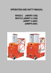
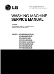
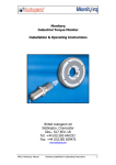
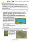
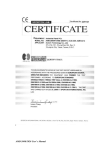
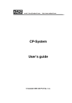
User‘s manual
Hydraulic road blocker
Series RKB/xxx
Manufacturer:
AUTOGARD spol. s r.o.
Dornych 47, 656 16 Brno, CZ
tel.: +420 - 545 214 149, fax.: +420 - 545 214 150
e-mail: [email protected]
http://www.autogard.cz
Návod k použití RKB
2
Acknowledgement:
Thank you for choosing our hydraulic road blocker. Our products are result of original construction and
are characterised by high technical performance and long operating life in all climatic conditions as a
result of top quality workmanship. All materials and components used are high – quality and are
tested during process of manufacture. Our products are designed for high performance, long trouble free lifetime and are nearly maintenance – free.
Our products are manufactured in accordance with classical technical standards and respond to
regulated technical norms.
Purpose of use:
For highest security level objects, defend against unauthorised entry of vehicles.
Forbidden manipulation:
It is prohibited to leave any burdens on or near the blocker!
Basic description:
Hydraulic road blockers RKB series are driven by rectilinear hydraulic motor connected to hydraulic
plant with electromotor, hydraulic pump device and electrically controlled switch board. Are designed
for intensive permanent duty. Blocker‘s control is provided by microprocessor control unit AGN2.0.
Blockers are made of steel plates class DIN UST 37-2 (EN S235 JRG1) with hot – dip galvanizing
finish.
Technical datas:
RKB/250 RKB/300 RKB/320 RKB/350 RKB/400
Motor
power suppl
control unit
Uplift height
Uplift speed
Number of pistons
Dimensions(mm)
Weight
Control unit
400V/50Hz 750W
230V/50Hz
100W
650 mm
7
1
2800 x 770 x
1400
880kg
AGN 2.0
400V/50Hz 750W
230V/50Hz
100W
650 mm
7
1
3300 x 770 x
1400
965kg
AGN 2.0
400V/50Hz 750W
230V/50Hz
100W
650 mm
7
1
3500 x 770 x
1400
400V/50Hz 1500W
230V/50Hz
100W
650 mm
7
2
3800 x 770 x
1400
400V/50Hz 1500W
230V/50Hz
100W
650 mm
7
2
4300 x 770 x
1400
AGN 2.0
AGN 2.0
AGN 2.0
© Autogard spol. s r.o. 2007
Návod k použití RKB
3
Dimensional drawing:
A (mm)
RKB/250
2 500
RKB/300
3 000
RKB/320
3 200
RKB/350
3 500
RKB/400
4 000
Tolerance +- 5mm
B (mm)
2 634
3 134
3 334
3 634
4 134
C (mm)
2 800
3 300
3 500
3 800
4 300
:
Construction preparation:
Drawing:
© Autogard spol. s r.o. 2007
Návod k použití RKB
4
Reality according the drawing:
Pic.1
Foundation plate concreting where blocker is settled
© Autogard spol. s r.o. 2007
Návod k použití RKB
5
Pic.2
Blocker‘s frame settling on top of foundation plate
Obr.3
Settled blocker + second plate with drainage pipe
© Autogard spol. s r.o. 2007
Návod k použití RKB
6
Hydraulic plant - Introduction:
Hydraulic mechanisms are integral parts of modern machines and equipments. In
following chapters some advices will be introduced to you witch will help you with
maintenance of hydraulic equipments.
Hydraulic fluids
Quality, cleaness and operational viscosity of hydraulic medium are most important
for security of operation, economy and life time. Component cathalogues include suitable oil
and range of viscosity recommendation.
Viscosity
Recommended viscosity by gear – pumps ranges (20 : 120) mm2.s-1 and oil
temperature ranges (-15 – 80) oC Maximum permitted viscosity is 700mm2.s-1. Viscosity
depends on temperature, from this reason maximum and minimum temperature in tank has to
by complyed with. Generally cooling or heating or both of oil is necessary. Even though
problems remain, different class of viscosity oil has to be used.
Other hydraulic parts (switch boards, pressure valves, throttles, etc.) have
recommended viscosity ranging (10 – 500) mm2.s-1 and oil temperature ranging (O – 75) oC.
Oil type
For all used hydraulic parts is suitable mineral oil HLP according to norm DIN51525,
part 2 – oils with protection ingredients against rust, oxidation and attrition protection.
Oil filtration
Generally class of oil cleaness 9 in accordance with NAS 1638 is necessary. This class
can be reached by filtration with coefficient β20≥75.
To ensure long life time class 8 in accordance with NAS 1638 is recommended. This
class can be reached by filtration with coefficient β10≥100.
Fresh, unused oils don‘t usually meet cleaness standards. Elaborate filtration is
necessary when filling the equipment, this means filling the tank with unfiltred oil is
inadmissible and causes termination of warranty.
Filtration fillers and oil are to be replaced after 1000 of working ahours, maximum
after one year and everytime sensor signalises filter choking.
Hydraulic plant description
Hydraulic plant forms a complex unit. Basic part is tank with removable or
unremovable front lid. Hydraulic driver is mounted vertically or horizontally on the lid also
air filter and block with hydraulic units is mounted there. According to needs also electric
level gauge with thermoregulater or accumulator can be mounted on the lid.
© Autogard spol. s r.o. 2007
Návod k použití RKB
7
Tank
Tank is welded from steel plates and creates structural part of hydraulic plant. When
tank size up to 60 dm3 upper lid is removable, in case of bigger tank upper lid is welded and
on the front side of tank there is removable cleaning lid. There is also visual level gauge with
thermometer on the front side. There is a discharge outlet in the bottom of the tank.
Drive
Drive is created by electromotor, pump device, flexible coupling and fixative flange.
Constant pump device drives with electromotor output up to 7,5 kW are placed vertically in
the tank, drives with bigger electromotors are fixed through flexible coupling.
Filter
Filter is used as waste filter or pressure filter according to the plant construction and
customer‘s wish.
Electric level gauge
Used according to customer‘s wish. Usually set to monitor maximum and minimum
oil level in tank.
Thermometer
According to customer‘s wish when cooler used. Usually set to monitor minimum
temperature (30°C) and maximum temperature (50°C).
Hydraulic accumulator
Hydraulic accumulators are supplied either diaphragmal or piston in suitable sizes.
Cooler
When neccesary hydraulic plant is equipped with air or water oil cooler which is fixed
to the side of tank.
Hydraulic components block
Blocks are used to minimize space demands of hydraulic circuits, to maximize lucidity
and cut – down the possibility of oil leaking.
Hydraulic plant parameters
Hydraulic plant type
Serial number
Tank cubature
Supplied quantity
Working pressure
Main electromotor input
Main electromotor revolutions
MA-701-01-07
M041 07 – M047 07
V = 5dm3
Q1 = 3dm3.min-1
p1 = 100bar
P1 = 0,75kW
n1 = 1410min-1
© Autogard spol. s r.o. 2007
Návod k použití RKB
8
Electromotor voltage
Hydraulic components inductor
tension
Hydraulic fluid
Optimal working temperature
Filtration
400/230V; 50Hz
24V DC
mineral oil class HLP, VG 32 - 46
(25-55)°C
minimum cleaness class - 9 according to NAS 1638
- 18/15 according to ISO/DIN4406
Filtration elements recommended ß10>=100
< 80 dB(A)
Hlučnost
Hydraulic plant connection
According to hydraulic diagram.
Piping
Various types of piping are used in hydraulic systems according to inside diameter and
working pressure.
Piping connection
Most used type of piping connection is screwing with notch ring.
Filling tank with oil
-
Carefully check tank‘s inner space
Fill with producer recommended oil only
Never fill with oil straight from the barrel, always use filtration aggregate with minimum
filtration capability 25 µm
Activity before setting hydraulic device in operation
Before setting in operation it is necessary to check:
-
Filling tank with prescribed oil up to maximum level
Cleaness of piping, fastening all connection elements
Connection according to hydraulic diagram
Connection between electromotor and pupm device
Wiring of electromotor, check if level, temperature and pressure sensors work
If filters are mounted correctly, if they have prescribed filtration capacity
If inner pupm spaces are full of oil
If pressure valves are set to minimum pressure
Activity during setting hydraulic device in operation
-
Set pump in operation in short intervals
Check noisiness of pump and tightness of piping
Deaerate hydraulic circuit
Check circuit function with minimum load if possible
Boost pressure to prescribed working level and set other regulating elements
During operation check control and measuring devices, noisiness, temperature and level
of oil in tank
© Autogard spol. s r.o. 2007
Návod k použití RKB
-
-
9
Check oil level according to visual level indicator – maximum oil level in tank is
indicated by red guideline in upper part of loophole
Check all functions simultaneously and compare these with projected calibres
Check pressure declivity on filters
Hydraulic plant electric connection
Electric installation, electromotors and control components power supply must
correspond to valid norms, namely EN 60 204-1. Before connecting to the system check
cathalogues values of working tension and frequency.
Hydraulic plant maintainance
Hydraulic plant maintainance is carried out planned and when neccesary.
Working liquid refilling
In principle always refill with the same liquid system is filled with. Mind this principle
even when filling mineral oils which satisfy normative regulation but may be different in
basic ingredients.
Working liquids class HFA, HFC and HFD may not be mixed at all.
Working liquid replacement
Every time working liquid starts to change it‘s chemist it is necessary to be replaced.
Filtration fillers have to be replaced every 1000 working hours, max. after one year. It is
necessary to rinse hydraulic liquid tank and whole hydraulic system. New liquid has to be
pumped over to the tank through filters which have at least the same filtration efficiency as
working filters in hydraulic circuit. Filter fillings have to be replaced at the same time as well.
Pressure setting
Pressure setting on pressure valves has to be checked continously. Valves may not be set to higher presures
then noted in hydraulic diagram in any case.
Piping check for leaking
Leaking parts have to be repaired when there is no pressure in piping only, leaking parts have to be
replaced.
Hydraulic plant cleaning
Hydraulic plant has to be kept clean, avoid water and impurity intrusion in the
hydraulic circuit. When using high – pressure cleaning devices make sure not to damage parts
of hydraulic device.
Accumulator maintainance
In case of any accumulator manipulation it is necessary to decompress the hydraulic
accumulator and make sure liquid from the hydraulic circuit not to get into the accumulator.
Always follow accumulator service manual. Hydraulic accumulators are always filled with
nitrogen.
© Autogard spol. s r.o. 2007
Návod k použití RKB
10
Worn-out parts replacement
Worn-out parts are to be replaced by original parts according to spare parts list. In case of
need it is possible
Security of work
Hydraulic circuits are safe and reliable even at high pressures as far as all components
are correctly dimensioned and operated. Always follow these principles:
– Never use hydraulic components dimensioned for lower pressures than circuit working
pressure
– Keep clean hydraulic plant environment
– Shield hydraulic plant from mechanical damage and source of heat
– In case circuit is under pressure it is recommended not to come near piping and hosing
– Do not smoke or handle with open fire near the hydraulic plant
– When doing any adjustments switch off electric installations and decompress the
accumulators
– All hydraulic circuits have to be protected gainst overload with correctly set safety valve
– Responsible employee must be determined to maintain hydraulic plant
– Ekvivalent acoustic pressure level A at service working station when weight filter A
exceed 85 dB (A), acoustic output level emitted by hydraulic plant doesn‘t exceed 85dB
(A)
– Hydraulic plant may not be used for different purpose and different materials than noted in
the service manual
– When hydraulic plant liquidated it is necessary to empty oil first
– When extinguishing fire or hydraulic plant carbon dioxide fire extinguisher has to be used
with respect to the electro installation
– Hydraulic plant and pressure circuits, especially when pressure hosing is used, should be
covered in the direction toward service
These principles are not complete. Every hydraulic circuit has different conditions and
different possibilities of environment threat. Following these rules should contribute to
improvement of user‘s working conditions.
Spare parts
Any spare part can be oredered by the hydraulic plant supplier. Following datas have
to be brought in when ordering:
– type of hydraulic component according to the list of components
– type and serial number of hydraulic plant according to the plant‘s label
– number of pieces ordered
Enclosures:
-
hydraulic diagram
hydraulic parts list
revisory book
© Autogard spol. s r.o. 2007
Návod k použití RKB
11
Hydraulic diagram:
© Autogard spol. s r.o. 2007
Návod k použití RKB
12
Hydraulic parts list:
PositionQuantity MJ Name
2
1,0 ks
3
1,0 ks
4.1
1,0 ks
4.2
1,0 ks
5
1,0 ks
6
1,0 ks
7.1
1,0 ks
7.2
1,0 ks
7.3
1,0 ks
7.4
1,0 ks
7.5
1,0 ks
8
1,0 ks
9.1
1,0 ks
9.2
1,0 ks
9.3
1,0 ks
10
1,0 ks
20
1,0 ks
Label
V60303006
Steel tank 5,0 l horizontal/vertical
V60603005
C1
Pump 1/2,5ccm
F27010002
Flange 0,55/0,75kW
F36100002
Junction 0,55/0,75kW
1LA7083-4AA12, 0,75/0,86kW,IMB14,FT100
M1
Flange-mounted electromotor
400/230V, 50Hz, n=1395 1/min
460V, 60Hz, n=1674 1/min
V60203003
Suction/draffish filter set
V60103021
Interplate with back-pressure valve TP3B
V70100003
Stopper with output for manometer
MA3-R1/4"-WD
Measuring connector
VSR1/4"-WD
Stopper
VST R 1/4 WD
V60513006
Console TP
VMP6C2001 (OR)
PV1
Safety valve
ORS30E00000
R1
No tension closed valve with manual emergency control
EC30D024CC
Inductor 24V DC for OR30 without connector
G1TU2VL1
Connector
LED 24V, AC/DCDIN 43650-A, 27,5x27,5
- overvoltage protection
CSC04C0000
SV1
Throttle valve with hydraulic gradient stabilization, Qmax = 40 l/min
PLV 32x40/406/692 113A113
HV1
Single acting hydraulic cylinder
© Autogard spol. s r.o. 2007
Návod k použití RKB
13
Revisory book:
Performed controls and and maintainance of hydraulic plant are registered in the
revisory book. Especially oil change and filtration fillers replacement is registered there. In
accordance with revisory book are viewed possible claims.
Date
Activity
Filling tank with oil
– type of oil:
– filtration device used:
© Autogard spol. s r.o. 2007
Name and signature
Návod k použití RKB
14
Control unit AGN2.0
Barriers of mod. AG500 a AG900 AGM1 are delivered with control unit AGN2.0 on microprocessor
basis which enable to adapt plug-in modules of radio receiver and loop detector.
Control unit AGN2.0 – connection schema:
Fuses:
fuse
F1
F2
Type
F
F
F3
F4
F
F
Value
1A
4 A (AG500, AG900)
10 A ( AGM1 )
1A
1A
© Autogard spol. s r.o. 2007
Návod k použití RKB
15
Description of AGN2.0 connectors :
Pin
L
N
PE
CASE
RED
GRN
N
PE
N
L1
L2
+
+
+
GND
COM
OPEN
CLOSE
S/S
COM
OPEN
Part
Signal
POWER
Power supply 230V AC – L wire
Power supply 230V AC – A wire
Power supply 230V AC – PE wire
CASE
case
SEMAPHORE Traffic light pin – phase on signal STOP
Traffic light pin – phase on signal FREE
Traffic light pin - common
MOTOR
Motor – PE wire
Motor - N wire
Motor – phase in direction open
Motor – phase in direction close
BRAKE
Motor brake 24V +
Motor brake 24V LAMP
Output for flashing lamp or lighting 24V AC
Output for flashing lamp or lighting24V AC
24V
Output 24V DC for power supply of accesories,
max 300 mA
START
Common pin for control inputs
Input of push-button „open“ (NO)
Input of push-button „close“ (NO)
Input of push-button „ step-step “ (NO)
LIMIT
Common pin for control inputs
Input of NC contact of limit switch upper position
CLOSE
COM
FOTO
Input of NC contact of limit switch low position
SAFE
STOP
DET
COM
ANT +
ANT
ANT GND
LOOP
DET
Common pin for control inputs
Input of safety contact FOTO ( blocks closing )
( NC )
Input of safety contact STOP of push-button
( blocks all move ) ( NC )
Input of loop detector contact ( NO) , function see
programmable functions , value 01
Common pin for control inputs
Input of antenna‘s central wire for plug-in receiver
of radio control
Input of antenna‘s shell for plug-in receiver of
radio control
Pins for connecting of inductive loop
Plug-in modules:
Connector
MODUL RADIO
Module
plug-in module of radio receiver – control the barrier following programmable
parameters. Suitable for type MRS2E receiver
MODUL DETECTOR plug-in module of presence detector – closing of barrier + safety function
Suitable for loop detectors of PLD1 type.
© Autogard spol. s r.o. 2007
Návod k použití RKB
16
a) Start of control unit:
After connecting of power supply red LED in upper right corner is switched-on and in the line
of LED behind the plug-in module relative LED according the activated inputs.
Than the systém is in a standard status, lines on display are blinking.It means the barrier will
work normally.
Standard function:
In case the boom is in closed position the control unit waits for command OPEN - UP. This
can be made by following kinds : Push-button UP, Push-button Step-Step or by radio transmitter. If
during the opening an opposite command is given the boom stops for ca.1s and then starts to move
the opposite way. During the closing cycle inputs FOTO and DET are tested. If they are active, the
boom again stops and starts to move contrary. Input STOP blocks all moves.
b) new setting of control unit:
By simultanous pressing of both programming buttons
you can entry to the programming modus. Number of
programmable function is displayed on. This number can be
changed with the help of programming keys UP and DW. Choose
number of function, you want to change. By simultanous pressing
of both programming keys you can entry to the parameters
settings of this function. Values can be changed again with
programming keys UP and DW following the table of
programmable functions. After setting of required values they are
saved by simultanous pressing of both keys and control unit returns to standard status (lines are
blinking ). When changing other parameters repeate the same way.
© Autogard spol. s r.o. 2007
Návod k použití RKB
17
Table of programmable functions:
Function –
number of
Description of function
item
01
DETECTOR – Choice of plug-in loop detector function
Function is disactivated (00) Safety ( 01), safety+closing ( 02 )
02
RADIO1 – Choice of relay A function of plug-in receiver
MRS2E
Open ( 00 ), or „step-step“ ( 01 )
03
RADIO2 – Choice of relay B function of plug-in receiver
MRS2E
Switched-off( 00 ), or „closing“ ( 01 )
04
LAMP – Choice of function of blinking lamp or warning lamp
Blinking only during the movement ( 00 ), or blinking full time( 01 )
05
FOTO – memory of closing pulse during break of input
FOTO.
Control unit disregards closing command during break of input
(00), closing command is memorised and after performed ( 01 ).
06
TIMER – setting of automatice reclosure time after opening
Reclosure is switched-off ( 00) , reclosure is activated, setted
value coresponds to the time of reclosure ( 01 – 99 )
07
DELAY – delay of start of closing after receiving command
close (pre-blinking of flashing light)
time of delay is setted in sec. ( 00 – 99 ).
08
Choice of time of switching traffic light on STOP
Traffic light is switched by activation of any safety inputs (when
the car is nearby the barrier)(00), traffic light is switched by
command (01).
09
Choice of plug-in detector type
detector PLD (02).
10
Values
Presetted
00 - 01
01
00 - 01
00
00 - 01
00
00 - 01
00
00 - 01
01
00 - 99
00
00 - 99
00
00 - 01
00
00 - 02
00
Stop on obstacle – if the boom bump on an obstacle motor will 00 - 20
00
stop.
Function is disactivated (00), function is activ, the time of
reaction is setted (O1 – 20).
11
Blocking of closing with input OPEN – If the contact on input 00 - 01
00
OPEN is switched-on, boom cannot be closed. Function is
disactivated (00) , or activated (01)
MODUL DETEKTOR násuvný detektor přítomnosti vozidla – zavírání závory + bezpečnostní funkce
Určeno pro detektory PLD – funkce viz . programovatelný parametr 01
© Autogard spol. s r.o. 2007
Návod k použití RKB
18
Loop detector PLD1 – 1-channel plug-in model
For safety functions and automatic closing the barrier after leaving the loop
insert plug-in loop detector module to socket "detector".
The safety loop connect to LOOP pins.
The head function of plug-in loop detector you can set with function no. 01(as
you require) and 09 (to value
02) in setup menu of AGN1.1
control unit.
Change DIP switch (on
AGN1.1 control unit)
according the picture (the arrow on the picture helps you).
If you want to use plug-in loop detector for opening the barrier, insert plug-in loop detector to socket "radio".
The loop connect to ANT pins. This type of function requires setting of function no. 02 to value 02.
You can also apply two plug-in loop detectors in control unit (first for opening, second for safety function and
closing), but the distance between opening and safety/closing loop must be more then 2 meters.
Setup ! After each device setting, a readjustment has to be made by pressing the reset key.
Dip switch 1,2
Frequency setting - with the frequency switches, several operationg frequencies per channel can be set in order
to avoid couplings by nearby loops.
Two ore more detectors may not operate at the same frequency.
Frequency high
S1 - left
S2 - left (delivery status:high)
right
left
left
right
Frequency low
right
right
Dip switch 3
Holding time (only relay A) - static (presence) - (S3 - on) or pulse 100 ms (S3 - off).
Dip switch 4,5,6
Sensitivity of the loop
DIP4 DIP5 DIP6 Function
on
on
on Sensitivity high
on
on
off
on
off
on
on
off
off Sensitivity med
off
on
on
off
on
off
off
off
on Sensitivity low
off
off
off DIP3 off - relay released - test operation
off
off
off DIP3 on - relay picked-up - test operation
Status LEDs
Detect - green LED – the switching status "Loop Covered" is signalled by shining of the green LED.
Error - red LED – A loop failure through loop short-circuit, disconnection or loop inductivity beyond a
permissible range is displayed by shining of the red LED.
Power – yellow LED – during the adjustment, the yellow LED is blinking for a few second. The yellow LED
will shine permanently after the adjustment.
! No vehicle may be on the loop during the adjustment phase, since it will then not be detected any more.
! After each device setting, a readjustment has to be made by pressiong the reset key.
© Autogard spol. s r.o. 2007
Návod k použití RKB
19
Technical datas
Power supply
Input
Inductive range
Sensitivity
Weight
Working temperatrure
Connector
Output
24 V DC, +/- 10%
3VA
15 uH – 2000 uH, recommended 100 – 300 uH, max 30 Ω
Adjustable in 7 levels
70g
-25oC up to +80oC
10ti pin MOLEX connector
Kontakty relé, Umax=250V, Imax=2A, Pmax=60W
Remote control Rxd1pp, Rxd2pp
Technical datas:
Power supply: 12-24 VAC/VDC
Frequency: 433,92 Mhz
Relay: 1A/30VDC
Working temperature: -20 - +60
Dimensions: 52x35x15 mm
1,2 channel plug-in receiver equipped with a 10 pole molex connector and outputs settable on customer‘s
request.
-
Via radio self learning functions allow to memorize up to 83 different codes
It is possible to delete a single code from memory and insert a new one
It enables to delete all the codes stored in memory and to insert new ones
It is possible to either enable or disable ROLLING CODE mode
Can be connected to portable programmer PROG2 by which it is possible to program the outputs with three
different functions – monostable, bistable and timer
PROGRAMMING
Select desired channel reffering to the table below:
Selected channel
Channel 1 monostable
Channel 2 monostable
Touch nr. On SW1
1
2
LED L1 LED L2
*
*
-Press a times receiver switch SW1 according to the table:LED LIGHT UP
- It is necessary to proceed to the programming step within 7 seconds
- Press the transmitters button until the receiver LED turn off for 1/2 second: this states that the code has been
memorized
- LED immediately starts flashing for a number of timesequal to the memory cell just occupied
© Autogard spol. s r.o. 2007
Návod k použití RKB
20
- After the flashing finishes, the system is ready to be used
BISTABLE AND TIMER FUNCTION PROGRAMMING
Using portable programmer PROG 2, it is possible to program receiver outputs either as BISTABLE or TIMER
„ROLLING CODE“ MODE
It is possible to enable or disable the „ rolling code“ mode , which vanishes any attempt to duplicate Personal
Pass code. It is necessary to set J1 jumper on the board:
J1 open ………… rolling code mode enabled
J1 close ………... rolling code mode disabled
WARNING: only with rolling code enabled Personal Pass code cannot be reproduced by others
PARTIAL DELETING FUNCTION
It is possible to delete one or more codes present inside the memory with aim to disable the desired transmitters.
To enable partial deleting function, act as below:
-
Press SW1 on the receiver and keep it pressed until LED turns off
Release switch: LED must start flashing (from 1 to 83) at a low rate(about 1 blink/second)
Count LED number of flashes till the memory cell number wished to delete
Press SW1 switch on the receiver during the wished flash count
Release SW1 switch and wait some seconds until LED goes off
The selected memory cell is now free and ready to be memorized again
TOTAL CLEARING
It is necessary to follow steps below:
-
Disconnect receiver alimentation
Press and keep pressed SW1 switch on the receiver
At the same time reconnect alimentation
Receiver LED flashes: release SW1 switch
All the 83 memory cells are now empty and ready to be programmed again
ATTEMPT TO INSERT A CODE ALREADY PRESENT IN MEMORY
While trying to memorize a code that is already present inside memory, receiver LED makes a number of flashes
equal to the memory cell number already occupied. To differentiate this function from normal programming
mode, LED flashes at a higher rate and remains on for about 4 sec. during last blink. The user can employ this
feature to identify, at every time, the memory cell of any transmitter having access to the system..
Emergency barrier opening
© Autogard spol. s r.o. 2007
Návod k použití RKB
21
Hydraulic valve release. Check picture below
! Emergency blocker opening or closing can be carried out only when
blocker‘s circuit breaker shut off !
Blocker maintainance
Blocker is designed and manufactured as a maintainance free facility. For permanent trouble free
function we advise to carry out activities as below every three months:
1) Check foundations of blocker
2) Control all screw connections and in case of need tighten them
3) Oil blocker pivots
Possible control modes
¾
¾
¾
Remote radio control
Inductive detector control
Card, contact card or contactless card access systems
Recommended accessories
9
9
9
9
9
9
9
9
9
Inductive detector
Safety photocell
Remote control
Key switch
Button control
STOP sign
Access systems
Drive-up ramp
Second traffic light for both way access
ES – Declaration of conformity
1)
Us
AUTOGARD spol. s r.o.
Dornych 47
617 00 Brno - CZ
IČ: 49446053
© Autogard spol. s r.o. 2007
Návod k použití RKB
22
Hereby declare,
That subsequently marked product on the basis of it‘s conception and construction, as well
as implementations set afloat by us, correspond to relevant basic security demands of
European directions. This declaration loses its validity when product characteristics are
changed without our reconciliation.
Product name:
Series:
Technical datas:
Manufacturer:
Automatic road blocker
RKB/xxx
400V / 50 Hz – 1500W
230V / 50 Hz – 100W
AUTOGARD spol. s r.o.,
Dornych 47, 617 00 Brno - CZ
Description and purpose of use: Automatic road blocker serves to regulate vehicles
entrance/exit to restricted areas.
The relevant decrees of the government / the European directives:
The Decree of the Government No. 168/1997 Coll. as amended (the Directive of the
European Council 93/68/EEC),
The Decree of the Government No. 169/1997 Coll. as amended (the Directive of the
European Council 93/68/EEC),
The Decree of the Government No. 170/1997 Coll. as amended (the Directive of the
European Council 98/37/EEC).
The applied harmonised standards, national standards and technical specifications:
ČSN EN 60204-1:2000 (EN 60204-1:1997), ČSN EN 61000-6-3:2002 (EN 61000-6-3:2001),
ČSN EN 61000-6-1:2002 (EN 61000-6-1:2001), ČSN EN 292-1:2000 (EN 292-1:1991),
ČSN EN 292-2+A1:2000 (EN 292-2+A1:1995)
Under conditions of common and determined using the product is safe.
The manufacturer has taken precautions for ensuring of the conformity of all launched
products with the technical documentation and wit the requirements of the technical
standards mentioned above.
Brno, 20.4.2007
………………………………
Place of issue,date
Ing. Milan Plhák
Jednatel
………………………….
Name and function
Of responsible person
© Autogard spol. s r.o. 2007
……………………..
Signature
Návod k použití RKB
23
Single test record according to ČSN 50106:
Test name
Required values
Conclusion
Security connection test
R < 0,1 ohm
Machinery pleased
Disruptive strength test
V = 2,5 kV time 1s
Machinery pleased
Function test
Setting, adjusting control
Machinery pleased
Completeness and quality certificate
Machinery is complete with all accessories and equipment, without defects.
Type
RKB/
Serial number
Tested by
© Autogard spol. s r.o. 2007
Návod k použití RKB
24
Content
Acknowledgement:................................................................................................... 2
Purpose of use: ........................................................................................................ 2
forbidden manipulation:........................................................................................... 2
Basic description: .................................................................................................... 2
Technical datas: ....................................................................................................... 2
Dimensional drawing: .............................................................................................. 3
................................................................................. Chyba! Záložka není definována.
Construction preparation : ...................................................................................... 3
Hydraulic plant - introduction.................................................................................. 6
Hydraulic fluids....................................................... Chyba! Záložka není definována.
Viscosity.................................................................................................................... 6
Oil type ...................................................................................................................... 6
Oil filtration ............................................................. Chyba! Záložka není definována.
Hydraulic plant description ..................................................................................... 6
Tank ........................................................................................................................... 7
Drive .......................................................................................................................... 7
Filter........................................................................................................................... 7
Electric level gauge .................................................................................................. 7
Thermometer............................................................................................................. 7
Hydraulic accumulator ............................................................................................. 7
Cooler ........................................................................................................................ 7
Hydraulic components block................................................................................... 7
Hydraulic plant parameters ..................................................................................... 7
Hydraulic plant connections.................................................................................... 8
Piping......................................................................................................................... 8
Piping connection .................................................................................................... 8
Filling tank with oil ................................................................................................... 8
Activity before setting hydraulic device in operation ........................................... 8
Activity during setting hydraulic device in operation ........................................... 8
Maintainance............................................................................................................. 9
Spare parts.............................................................................................................. 10
Hydraulic diagram .................................................................................................. 11
Hydraulic parts list ................................................................................................. 12
Revisory book......................................................................................................... 13
Control unit ............................................................................................................. 14
Loop detector.......................................................................................................... 18
Remote control ....................................................................................................... 19
Emergency blocker oprning .................................................................................. 20
Blocker maintainance............................................................................................. 21
Possible control modes ......................................................................................... 21
Recommended accessories. ................................................................................. 21
ES - Declaration of conformity .............................................................................. 21
Single test record ................................................................................................... 23
Completeness and quality certificate ................................................................... 23
Content .................................................................................................................... 24
© Autogard spol. s r.o. 2007
Contacts
In Russia, please contact AbavaNet to maintain or purchasing:
AbavaNet,
tel.: +7 495 921 7991
[email protected]
www.abava.net
105005, Russia, Moscow, Radio st., 24