1
MODEL
NR 90AC2
POWER TOOLS
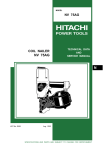
STRIP NAILER
NR 90AC2
TECHNICAL DATA
AND
SERVICE MANUAL
N
LIST No. E002
Sep. 2001
SPECIFICATIONS AND PARTS ARE SUBJECT TO CHANGE FOR IMPROVEMENT
REMARK:
Throughout this TECHNICAL DATA AND SERVICE MANUAL, a symbol(s)
is(are) used in the place of company name(s) and model name(s) of our
competitor(s). The symbol(s) utilized here is(are) as follows:
Competitors
Symbols Utilized
Company Name
Model Name
P
SENCO
SN65C
Q
Paslode
F-350SRH
CONTENTS
Page
1. PRODUCT NAME ........................................................................................................................... 1
2. MARKETING OBJECTIVE ............................................................................................................. 1
3. APPLICATIONS .............................................................................................................................. 1
4. SELLING POINTS .......................................................................................................................... 1
5. SPECIFICATIONS .......................................................................................................................... 2
5-1. Specifications .................................................................................................................................. 2
5-2. Nail Selection .................................................................................................................................. 3
5-3. Nail Driving Force ........................................................................................................................... 3
5-4. Optional Accessories ...................................................................................................................... 4
6. COMPARISONS WITH SIMILAR PRODUCTS .............................................................................. 5
7. PRECAUTIONS IN SALES PROMOTION ..................................................................................... 6
7-1. Instruction Manual .......................................................................................................................... 6
7-2. Warning Label ................................................................................................................................. 6
7-3. Related Laws and Regulations ....................................................................................................... 7
8. MECHANISM AND OPERATION PRINCIPLE ............................................................................... 8
8-1. Mechanism ..................................................................................................................................... 8
8-2. Interchangeability ............................................................................................................................ 9
8-3. Operation Principle ........................................................................................................................ 11
9. TROUBLESHOOTING GUIDE ..................................................................................................... 13
9-1. Troubleshooting and Correction .................................................................................................... 13
9-2. Possible Causes and Corrections of Air Leakage ......................................................................... 16
10. DISASSEMBLY AND REASSEMBLY ........................................................................................ 18
10-1. General Precautions in Disassembly and Reassembly .............................................................. 18
10-2. Disassembly and Reassembly of the Output Section ................................................................. 19
10-3. Disassembly and Reassembly of the Control Valve Section (See Fig. 12.) ............................... 21
10-4. Disassembly and Reassembly of the Driving Section (See Fig. 16.) .......................................... 24
10-5. Disassembly and Reassembly of the Cap and the Magazine Section ....................................... 25
11. INSPECTION AND CONFIRMATION AFTER REASSEMBLY .................................................. 28
12. STANDARD REPAIR TIME (UNIT) SCHEDULES ..................................................................... 29
Assembly Diagram for NR 90AC2
1. PRODUCT NAME
Hitachi 90 mm (3-12") Strip Nailer, Model NR 90AC2
2. MARKETING OBJECTIVE
The Model NR 90AC2 strip nailer is an upgraded version of the current Model NR 90AC, equipped with the
demands for improvement but remained its powerful driving force capable of driving round-head nails. We are
confident that your sales will increase with the new Model NR 90AC2. Primary improvements made to the Model
NR 90AC2 are described below.
(1) The magazine section is simplified:
The material of the magazine is changed from nylon (constructed of two parts) to extruded aluminum in order
to increase the strength and to reduce parts count (NR 90AC: 27 parts
NR 90AC2: 20 parts).
(2) A dust filter is added to the air inlet to prevent dust from getting in the machine.
(3) The grip tape is changed to the long-life grip rubber.
(4) The piston ring is changed to the O-ring.
(5) The material of the O-ring used in the head valve section is changed to swell-resistant material.
(6) The shape of the pushing lever spring is changed to prevent settling.
3. APPLICATIONS
Floor and wall framing
Truss build-up, window build-up
Subflooring and roof decking
Wall sheathing
Mobile home and modular housing construction
4. SELLING POINTS
Equipped with a rubber grip
Equipped with a dust filter
Rear loading type
Simple and high-strength
aluminum magazine
(NR 90AC: nylon magazinne)
Equipped with a
pushing lever stopper
(idling protector)
--- 1 ---
5. SPECIFICATIONS
5-1. Specifications
NR 90AC2
Model
Driving system
Reciprocating piston type
Operating pressure
5 --- 8.5 kgf/cm2 (70 --- 120 psi, 4.9 --- 8.3 bar) (Gauge pressure)
Driving speed
3 pcs./sec.
Weight
4.0 kg (8.9 lbs.)
Dimensions
(Length x Height x Width)
503 mm x 353 mm x 121 mm
(19-13/16" x 13-7/8" x 4-3/4")
Nail feed system
Spiral spring
Nail capacity
50 to 60 nails (2 strips)
Air consumption
2.7 ltr/cycle at 7 kgf/cm2 (0.095 ft3/cycle at 100 psi) (2.7 ltr/cycle at 6.9 bar)
Air inlet
3/8 NPT thread
Packaging
Corrugated cardboard box
Package dimensions
(Length x Height x Width)
587 mm x 398 mm x 136 mm
(23-1/8" x 15-21/32" x 5-11/32")
Standard accessories
Optional accessories
Nose cap (Code No. 881968) ...................................................................
Hex. bar wrench for M5 screw (Code No. 944458) ....................................
Hex. bar wrench for M6 screw (Code No. 944459) ....................................
Hex. bar wrench for M8 screw (Code No. 872422) ....................................
Eye protector (Code No. 875769) ..............................................................
Sequential fire parts set (Code No. 881973)
Pneumatic tool lubricant (1 oz oil feeder) (Code No. 877153)
Pneumatic tool lubricant (4 oz oil feeder) (Code No. 874042)
Pneumatic tool lubricant (1 quart can) (Code No. 876212)
Grease (ATTOLUB No. 2) (500 g (1.1 lbs.)) (Code No. 317918)
Case (Code No. 878898)
--- 2 ---
1
1
1
1
1
5-2. Nail Selection
The Model NR 90AC2 utilizes round-head nails collated with plastic resin into bands of 25 to 30 pieces.
Applicable nail dimensions are shown below.
CAUTION:
Ensure that nails are as specified in Fig. 1. Other nails will cause clogging of nails and
subsequent damage to the nailer.
Plastic-collated strip nails full-head nails
Maximum
Minimum
8.3 mm
(0.327")
90 mm (3-1/2")
60 mm (2-3/8")
7 mm
(0.286")
2.9 mm
(0.113")
4.1 mm
(0.162")
20 deg.
Min. 13 mm
(0.5")
Max. 41 mm
(1.6")
Fig. 1 Dimensions of nails
5-3. Nail Driving Force
Fig. 2 shows by type of wood and nail, the nailer output energy provided by the supply pressure and the nailing
energy required for driving the nail flush. Air pressure which exceeds the intersecting point between the nailer
output energy and the required nailing energy required for driving the nail allows the nail to be fully driven.
For example, when driving a nail of 4.1 mm dia. by 90 mm length (0.162" x 3-1/2") into a workpiece of hemlock
spruce with he Model NR 90AC2, a pressure of about 6.4 bar (6.5 kgf/cm2, 92 psi) allows the nailer to drive the
nail flush to the wood surface. A pressure beyond this value causes the nail head to be driven below the wood
surface. Fig. 2 should be used as reference data because those values vary depending on the type, moisture
content, and grain of wood.
--- 3 ---
NR 90AC
NR90AC2
Hemlock spruce
P
Q
Air pressure setting to drive nail flush
with NR 90AC2
Fig. 2 Required nailing energy and nailer output energy
5-4. Optional Accessories
Sequential fire parts set:
The Sequential Fire Parts Set is provided as an optional accessory for the Model NR 90AC2. By using this
optional accessory, a nail is driven by pressing the push lever first against a workpiece and then pulling the trigger,
and no nail is driven when pulling the trigger first and then pressing the push lever against a workpiece (singleshot operation). Please recommend the sequential fire parts set to the customers who want to use it.
Salespersons must instruct the customers to read the Handling Instructions attached to the sequential fire parts
set and also the Handling Instructions of the Model NR 90AC2 thoroughly for correct use.
--- 4 ---
6. COMPARISONS WITH SIMILAR PRODUCTS
HITACHI
Maker
Model
Operating pressure
Weight
Dimensions
(L x H x W)
Air consumption at
7 kgf/cm2 (100 psi)
Nail capacity
(3-1/2 x .162")
NR 90AC
5 -- 8.5 kgf/cm2
(70 -- 120 psi)
P
Q
5 -- 8.5 kgf/cm2
(70 -- 120 psi)
5.6 -- 8.5 kgf/cm2
(80 --- 120 psi)
4.0 kg (8.9 lbs.)
4.3 kg (9.5 lbs.)
3.7 kg (8.2 lbs.)
3.9 kg (8.6 lbs.)
501 x 343 x 111 mm
(19-3/4 x 13-5/8 x 4-3/8")
569 x 332 x 130 mm
(22-13/32 x 13-1/16 x 5-1/8")
548 x 353 x 121 mm
503 x 353 x 121 mm
(19-13/16 x 13-7/8 x 4-3/4") (21-9/16 x 13-7/8 x 4-3/4")
2.7 ltr/cycle
(.095 ft3/cycle)
2.7 ltr/cycle
(.095 ft3/cycle)
2.3 ltr/cycle
(.081 ft3/cycle)
2.4 ltr/cycle
(.085 ft3/cycle)
50
50
50
50
Rear loading
(Aluminum)
Top loading
(Plastic)
Rear loading
(Aluminum)
Top loading
(Aluminum)
Tool not required
Tool not required
With wrench
With wrench
Provided
Not provided
Provided
Not provided
Tool not required
Tool not required
With wrench
With wrench
Rubber
Racket grip
Leather
Rubber
Dia.
2.9 -- 4.1 mm
(0.113 -- 0.162")
2.9 -- 4.1 mm
(0.113 -- 0.162")
2.9 -- 4.1 mm
(0.113 -- 0.162")
Length
60 -- 90 mm
(2-3/8 -- 3-1/2")
60 -- 90 mm
(2-3/8 -- 3-1/2")
2.9 -- 4.1 mm
(0.113 -- 0.162")
60 -- 90 mm
(2-3/8 -- 3-1/2")
Magazine type
Driving depth
adjustment mechanism
Idling protector
Direction change
of exhaust air
Handle grip
Applicable
nails
NR 90AC2
5 -- 8.5 kgf/cm2
(70 -- 120 psi)
Note:
The Model NR 90AC2 is equipped with a pushing
lever stopper as an idling protector. The Pushing
Lever Stopper [72] is placed over Pushing Lever (B)
[33] to prevent Pushing Lever (B) [33] from being
pushed up when no nail is loaded in the magazine
or the number of nails remained in the magazine is
five or less (depending on the types of nails).
(See Fig. 3.)
50 -- 90 mm
(2 -- 3-1/2")
Pushing Lever Stopper [72]
5
Pushing lever (B) [33]
Fig. 3
--- 5 ---
7. PRECAUTIONS IN SALES PROMOTION
In the interest of promoting the safest and most efficient use of the Model NR 90AC2 Nailer by all of our
customers, it is very important that at the time of sale the salesperson carefully ensures that the buyer seriously
recognizes the importance of the contents of the Instruction Manual, and fully understands the meaning of the
precautions listed on the Warning Label attached to each tool.
The Model NR 90AC2 Nailer is designed for continuous nail driving (however, some of the Model NR 90AC2 are
designed for single-shot operation only for some destinations). At time of sale, the salesperson must inform the
customer that the sequential trip mechanism kit which can change the Model NR 90AC2 to a single-shot nailer is
optionally available, and recommend it to the customers who want to use it. Refer to the leaflet attached together
with the Instruction Manual for details.
7-1. Instruction Manual
Although every effort is made in each step of design, manufacture, and inspection to provide protection against
safety hazards, the dangers inherent in the use of any pneumatic tool cannot be completely eliminated.
Accordingly, general precautions and suggestions for use of pneumatic tools, and specific precautions and
suggestions for the use of the pneumatic nailer are listed in the Instruction Manual to enhance the safe, efficient
use of the tool by the customer.
Salespersons must be thoroughly familiar with the contents of the Instruction Manual to be able to offer
appropriate guidance to the customers during sales promotion.
7-2. Warning Label
Each Model NR 90AC2 unit is provided with a Warning Label (illustrated below) which lists basic safety
precautions in its use. Carefully ensure that customers fully understand and follow these precautions before using
the tool.
--- 6 ---
The following label is adhered to the Model NR 90AC2 for Europe to prohibit the use of the Model NR 90AC2
standing on a stepladder. Carefully ensure that customers fully understand and follow the precaution before using
the tool.
7-3. Related Laws and Regulations
As nailers and staplers are designed to instantaneously drive nails and staples, there is an ever-present danger of
misfiring and subsequent possible serious injury. Accordingly, close attention in handling is absolutely necessary
at all times. Carefully ensure that the customer is fully aware of the precautions listed in the Instruction Manual
provided with each unit.
While there are no specific safety regulations, there are related items in various general safety regulations with
which the salespersons should be familiar in order to properly advise the customer. Please check your national
and/or local regulations for applicable items. Some applicable items are outlined below.
The U.S.A:
OSHA
1926.102 Eye and face protection
1926.302 Power-operated hand tools
ANSI SNT-101-1993
Portable, Compressed-Air-Actuated,
Fastener Driving Tools-Safety Requirements for
--- 7 ---
8. MECHANISM AND OPERATION PRINCIPLE
8-1. Mechanism
As illustrated in Fig. 4, the Model NR 90AC2 can be generally divided into four sections:
output section, control valve section, driving section and magazine section.
The magazine section has been newly designed though its basic construction is the same as that of the Model
NR 90AC. Features of the main parts are described below.
Output section ................. Most parts are common to the Model NR 90AC except the following parts.
The dust filter is added to the cap. Owing to this addition, gasket (B) is changed.
The piston ring is changed to the O-ring.
The O-ring used in the head valve section is changed to swell-resistant type.
The rubber handle grip is adopted at the body ass'y.
Control valve section ....... The valve construction is similar to the Model NR 90AC.
Driving section ................ The nose and pushing lever (B) have been newly designed.
Magazine section ............ All the parts have been newly designed. The rear-loading type magazine is made
of aluminum and equipped with an idling protector.
Valve Piston (B) [54]
Plunger Spring [57]
Valve
Bushing (B) [51]
Plunger (A) [58]
Top Cover [3]
Exhaust Cover [5]
,
O-Ring
Valve Bushing (A) [60]
Output section
Exhaust vent
Exhaust Valve
Rubber [7]
Head Valve [10]
Control valve
section
Control valve section
Dust Filter [41]
Body [22]
Rubber
Accumulator
Cap [42]
Cylinder [17]
Piston [19]
Trigger (A) [46]
Driving section
Piston Bumper (A)
[24]
Piston Bumper (B)
[25]
Pushing Lever (B)
[33]
Adjuster (A) [ 34 ]
Pushing Lever (A)
[37]
Nail feeder ass'y
Nose [30]
Fig. 4 Construction
--- 8 ---
Magazine section
8-2. Interchangeability
The magazine section is not interchangeable between the Model NR 90AC2 and the NR 90AC because this
section of the Model NR 90AC2 have been newly designed. The output section, the driving section and the
control valve section are interchangeable except the following parts.
Part
NR 90AC2
Cylinder O-Ring (B) [9]
Material: Fluororubber
(The size is the same as the Model NR 90AC.)
Material: Nitrile rubber
Cylinder O-Ring [11]
Material: Fluororubber
(The size is the same as the Model NR 90AC.)
Material: Nitrile rubber
O-Ring [18]
Piston [19]
O-Ring
NR 90AC
Piston ring
O-Ring
The grooves made
to the O-ring are
different from the
Model NR 90AC.
O-Ring
Body [22]
Gasket (B) [40]
Dust Filter [41]
Piston ring
Dust filter is provided and
the shape of gasket (B) is
different from the Model
NR 90AC.
Grip rubber
--- 9 ---
Grip tape
Part
NR 90AC2
NR 90AC
NR 90AC2: 8 mm (0.315")
NR 90AC: 12 mm (0.472")
Nose [30]
NR 90AC2: 7 mm (0.276")
NR 90AC: 4.5 mm (0.177")
Spring [32]
Pushing Lever (B) [33]
Idling protector
Guard [28]
Collar (B) [29]
Protruded
Collar
NR 90AC: 13.3 mm (0.524")
NR 90AC: 10 mm (0.394")
--- 10 ---
8-3. Operation Principle
Exhaust Valve Rubber [7]
(1) Before nailing (See Fig. 5 and Fig. 6.)
Exhaust vent
1) When compressed air is fed to the main body, it
fills the accumulator (
portion).
2) At the same time, the compressed air flows into
Head valve chamber
Head Valve
Spring [8]
Air passage
Head Valve [10]
the valve piston lower chamber of the control valve
Control
valve
section
Accumulator
section and forces Valve Piston (B) [54] upward.
Compressed air is then fed through the air supply
Piston [19]
vent and air passage to the head valve chamber.
Cylinder hole
As a result, the Head Valve Spring [8] is pushed
Cylinder [17]
down to seal the Head Valve [10] and Cylinder
Trigger (A) [46]
Return air
chamber
[17].
(2) When nailing (See Fig. 4 and Fig. 5.)
1) When Pushing Lever (A) [37] and Trigger (A) [46]
are operated together and Plunger (A) [58] is
pushed upward, the compressed air in the valve
Pushing Lever (A) [37]
piston lower chamber is discharged from the
Nail
bottom of Plunger (A) [58]. As a result, the
compressed air in the accumulator (
portion)
Fig. 5
pushes down Valve Piston (B) [54], blocking the air
supply vent and opening the exhaust valve.
2) When the exhaust valve opens, the compressed
To the head valve chamber
air in the head valve chamber is discharged into
Air supply vent
Accumulator
the atmosphere through the air passage.
3) When the air pressure on the bottom surface of the
Head Valve [10] overcomes the strength of the
Head Valve Spring [8], the Head Valve [10] is
Air passage
pushed upward. At this time, the Head Valve [10]
seals with the Exhaust Valve Rubber [7], blocking
the passage to the exhaust vent.
4) When the Head Valve [10] goes up, the
compressed air in the accumulator flows rapidly
into the Cylinder [17], forcing the Piston [19]
downward to strike the nail. When the Piston [19]
passes the cylinder hole, the compressed air flows
into the return air chamber and is accumulated
there.
--- 11 ---
Exhaust
valve
Valve piston lower chamber
Valve Piston (B)
[54]
Plunger (A) [58]
Fig. 6 Control valve section
(3) During return (See Fig. 7 and Fig. 8.)
Exhaust Valve Rubber [7]
1) When either Pushing Lever (A) [37] or Trigger (A)
[46] is released, Plunger (A) [58] goes down and
Exhaust vent
the compressed air in the accumulator flows into
Accumulator
Head valve chamber
Air passage
Head Valve [10]
the valve piston lower chamber.
Control
valve
section
2) As the air pressure in the valve piston lower
Cylinder [17]
chamber increases to overcome the air pressure
applied on the upper portion of Valve Piston (B)
[54], Valve Piston (B) [54] is forced upward. When
this occurs, the exhaust valve is closed and the air
Piston [19]
supply vent is opened.
Trigger (A) [46]
Piston Bumper
(A) [24]
Piston Bumper
(B) [25]
3) When the air supply vent opens, the compressed
air in the accumulator (
Return air
chamber
portion) passes
through the air passage and flows into the head
valve chamber to push down the Head Valve [10].
Driver blade
As a result, the Head Valve [10] and the Cylinder
[17] are sealed and , at the same time, the Head
Pushing Lever (A)
[37]
Fig. 7
Valve [10] and the Exhaust Valve Rubber [7]
separate to open the exhaust vent.
To the head valve chamber
4) The compressed air above the Piston [19] is
Air supply vent
discharged into the atmosphere through the
Accumulator
exhaust vent. In this way, the air pressure above
the Piston [19] is reduced, and the greater
pressure of the air accumulated in the return air
Air passage
chamber pushes the Piston [19] upward.
5) If the air pressure below the Piston [19] is higher
than that of the atmosphere after the Piston [19]
has fully returned, the excess air pressure is
Exhaust
valve
Valve
Piston (B) [54]
discharged into the atmosphere through the
clearance between Piston Bumper (B) [25] and
Valve piston
lower chamber
Plunger (A) [58]
the driver blade.
Fig. 8 Control valve section
--- 12 ---
9. TROUBLESHOOTING GUIDE
9-1. Troubleshooting and Correction
Problem
Possible cause
1) Nails cannot
be driven.
<Nails>
Magazine is not loaded with
specified genuine nails.
Magazine is loaded with
abnormal nails (bent nails,
large or small round-head
nails, abnormal collation,
etc.).
Inspection method
Check if the magazine is
normally loaded with
specified nails.
Remedy
Use specified nails.
Remove the abnormal nails
and load the magazine with
normal nails.
Nail or collating band clogs.
Collating band is deformed
or torn.
<Magazine>
Magazine is abnormal
(deformed or damaged).
Nail feeder is abnormal
(deformed or damaged).
Ribbon spring is abnormal
(deformed or damaged).
Check if the nail feeder
operates smoothly in the
magazine.
Repair or replace the
defective part.
Check if nails (one strip)
move smoothly in the
magazine.
Nail rail is abnormal
(deformed, burrs, damaged
or fatigued).
Adhesive fragments are on
the nail rail or they need oil.
Remove the adhesive
fragments and apply oil to
the nail feeder, ribbon spring
and the nail rail.
Foreign matter is found on
the guide face of the nail
feeder.
<Nose>
Nail inlet groove of the nose
is abnormal (deformed,
burrs or damaged).
Check if nails (one strip) are
fed smoothly into the nail
injection port of the nose.
Repair or replace the
defective part.
Remove the adhesive
fragments.
Adhesive fragments are in
the nail inlet groove.
--- 13 ---
Problem
Possible cause
Inspection method
Remedy
Pull the nail feeder
backward and perform idle
driving. Check if the driver
blade has returned.
Adjust for 5 to 8.5 kgf/cm2.
Replace the piston ring.
<Output section>
Air pressure is too low.
Piston O-ring is worn or
damaged.
Piston bumper is abnormal
(dislocated, deformed or
damaged).
Replace the piston bumper.
O-ring of the cylinder is
abnormal (dislocated,
deformed or damaged).
Reassemble or replace.
Driver blade is abnormal
(deformed, burrs, damaged
or fatigued).
Repair or replace.
Cylinder's internal surface is
abnormal (deposits of dirt or
worn).
Head valve sliding surface is
abnormal (galled, damaged
or needs oil).
Check if nails can be driven
at 5 kgf/cm2.
Head valve spring is
abnormal (fatigued or
damaged).
After operating the nailer
without nails, check if the
driver blade is kept in the
down position.
Replace the head valve
spring.
After making idle driving,
check if the driver blade is
kept in the down position.
Replace the defective part.
Disassemble the control
valve and check the O-ring.
Apply grease, or replace.
<Control valve section>
Plunger (A), valve piston (B),
valve bushing (A) or valve
bushing (B) is abnormal
(galled or damaged).
O-ring is worn or oiling is
needed.
While operating the nailer
without nails, check if the
drivng operation is
performed.
--- 14 ---
Remove the dirt and apply
oil, or replace.
Replace the defective part.
Apply grease.
Problem
2) Nails are bent
when being
driven.
Possible cause
For short nails, the adjuster
is raised too high.
Check if the adjuster is
raised too high.
Nails are not fully fed into
the injection port.
Unspecified nails are used.
Driver blade is worn.
See item 1).
Workpiece is very hard.
3) Head of a nail
driven into a
workpiece
protrudes
from the wood
surface.
Inspection method
Adjuster is improperly
adjusted.
Air pressure is too low.
Workpiece is very hard.
Driver blade is worn.
Piston ring is abnormal
(worn or damaged).
Cylinder's internal surface is
abnormal (worn or rough).
Remedy
Turn the adjuster to the
lower position to decrease
the pressure.
See item 1).
Check if the driver blade tip
is abnormally worn.
Drive a nail into soft wood
workpiece and check if the
nail is bent.
Replace the driver blade.
Turn the adjuster to the
lowest position and drive a
nail.
Adjust the adjuster to the
proper position.
Drive a nail into soft wood
workpiece and check if the
head protrudes from the
wood surface.
Operate the nailer without
nails and check if the driver
blade is projected from the
nose tip.
Disassemble the output
section and check the
piston ring, O-ring and the
inner/outer surfaces of the
cylinder for abnormal
condition.
--- 15 ---
Do not use unspecified
workpieces.
Adjust for 5 to 8.5 kgf/cm2.
Do not use unspecified
workpieces.
Replace the drive blade.
Replace the defective part.
9-2. Possible Causes and Corrections of Air Leakage
Air leakage repair location
Repair procedure
(1) Check the points of the following parts marked by an
asterisk * for abnormal condition.
a
(A)
(2) Next, check the seal parts marked with a double
c
b
circle
for wear, flaw and damage.
(3) And then, check other places.
(B)
(G)
d
(C)
f
e
Control valve section
(D)
Possible cause
Air leakage point
With control valve OFF
A) Exhaust port
With control valve ON
Cylinder O-ring (B) [9] of the Head Valve
The Exhaust Valve Rubber [7] is abnormal
[10] is abnormal or its sliding surface a is
or the sliding surface c of the Head Valve
worn, deformed or flawed.
[10] is worn or flawed.
The Head Valve Rubber [12] is abnormal or
the sealing surface b of the Cylinder [17]
is worn or flawed.
B) Exhaust cover
The Hex. Socket Hd. Bolt (W/Flange)
M6 x 35 [4] is loose.
Gasket (A) [6] is damaged.
Seal surface of the Body [22] or the
Exhaust Cover [5] is abnormal.
--- 16 ---
Possible cause
Air leakage point
With control valve OFF
With control valve ON
C) Nose 1
The Cylinder O-ring [26] of the Body [22] or
the groove is abnormal (broken or flawed).
The Hex. Socket Hd. Bolt M8 x 30 [61] is
loose.
D) Nose 2
The O-ring (S-95) [14] of the Cylinder Plate
Piston Bumper (A) [24] is abnormal
[13] or the O-ring (I.D. 59.6/W2.4) [15] of
(portion d is damaged, deformed or
the Cylinder [17] is abnormal (broken or
cracked).
flawed).
The Piston [19] is abnormal (driver blade is
deformed or seal surface is deformed).
E) Control Valve 1
The O-ring (I.D. 11) [56] of Valve Piston (B)
The upper O-ring (I.D. 8.8) [55] of Valve
[54] is abnormal (worn, broken or flawed).
Piston (B) [54] is abnormal (worn, broken or
The lower O-ring (I.D. 8.8) [55] of Valve
flawed).
Piston (B) [54] is abnormal (worn, broken or
The Head Valve O-ring (I.D. 16.8) [50] of
flawed).
Valve Bushing (B) [51] is abnormal (broken
The O-ring (S-18) [52] of Valve Bushing (B)
or flawed).
[51] is abnormal (broken or flawed).
The upper surface f of the valve cavity of
The internal surface e of the valve cavity
the Body [22] is abnormal.
of the Body [22] is abnormal.
F) Control Valve 2
G) Cap
The O-ring (I.D. 1.8) [59] of Plunger (A)
The O-ring (S-4) [53] of Valve Piston (B)
[58] is abnormal (worn, broken or flawed).
[54] is abnormal (worn, broken or flowed).
Valve Bushing (A) [60] is abnormal (sliding
Valve Piston (B) [54] is abnormal (sliding
surface of Plunger (A) [58] is deformed or
surface of Plunger (A) [58] is deformed or
flawed).
flawed).
Gasket (B) [40] is damaged.
The Hex. Socket Hd. Bolt M5 x 16 [43] is loose.
Seal surface of the Body [22] or the Cap [42] is abnormal (damaged, deformed or flawed).
--- 17 ---
10. DISASSEMBLY AND REASSEMBLY
The items particularly necessary for disassembly and reassembly are described below. The [Bold] numbers in
the descriptions below correspond to the item numbers in the Parts List and exploded assembly diagram.
[CAUTION]
Before disassembly or reassembly, be sure to remove all nails and disconnect the air hose from the
nailer (with your finger released from the trigger) to exhaust all the compressed air.
10-1. General Precautions in Disassembly and Reassembly
Apply grease (ATTOLUB No. 2) (Code No. 317918) to the O-rings and O-rings' sliding portions.
When installing the O-rings, be careful not to damage the O-rings and prevent dirt entry.
Oil required: Hitachi pneumatic tool lubricant
1 oz (30 cc) oil feeder (Code No. 877153)
4 oz (120 cc) oil feeder (Code No. 874042)
1 quart (1 ltr) can (Code No. 876212)
If Gasket (A) [6] is damaged, replace it and check that no air is leaking.
Be especially careful to prevent the entry of foreign particles into the control valve section.
Tightening torque for each part
Tightening torque N•m (kgf•cm, ft-lb)
Bolt
Hex. Socket Hd. Bolt M8 x 30 ....................................... [61]
25.5
2 (260
20, 18.8
1.4)
Hex. Socket Hd. Bolt M6 x 16 ....................................... [1]
12.7
0.8 (130
8, 9.4
0.6)
Hex. Socket Hd. Bolt M6 x 12 ....................................... [39]
12.7
0.8 (130
8, 9.4
0.6)
Hex. Socket Hd. Bolt (W/Flange) M6 x 35 .................... [4]
12.7
0.8 (130
8, 9.4
0.6)
Nylock Bolt (W/Flange) M6 x 20 .................................... [27]
12.7
0.8 (130
8, 9.4
0.6)
Hex. Socket Hd. Bolt (W/Flange) M6 x 12 .................... [77]
9.8
0.8 (100
Hex. Socket Hd. Bolt M5 x 16 ....................................... [43]
6.4
0.5 (65
--- 18 ---
8, 7.2
5, 4.7
0.6)
0.4)
10-2. Disassembly and Reassembly of the Output Section
(1) Disassembly and reassembly of the Exhaust Cover [5], Head Valve [10], Exhaust Valve Rubber [7], etc.
(See Fig. 9A and Fig. 9B.)
[Tools required]
Hex. bar wrench (5 mm)
Hex. Socket Hd. Bolt
M6 x 16 [1]
Hammer
Plate [2]
(a) Disassembly
Top Cover [3]
Remove the four Hex. Socket Hd. Bolt (W/Flange)
M6 x 35 [4] with a hex. bar wrench. The entire Exhaust
Hex. Socket Hd. Bolt
(W/Flange)
M6 x 35 [4]
Cover [5] can now be removed from the Body [22].
Remove the Hex. Socket Hd. Bolt M6 x 16 [1] with a hex.
bar wrench. The Plate [2] and the Top Cover [3] can now
Exhaust Cover [5]
be removed.
Gasket (A) [6]
As shown in Fig. 9B, insert a 4 to 5 mm dia. bar into the
hole of M6 screw in the Exhaust Cover [5] and force out
the Exhaust Valve Rubber [7] with a hammer. Now, the
Exhaust Valve
Rubber [7]
parts forming the Exhaust Valve Rubber [7] can be taken
out.
Head Valve Spring [8]
[CAUTION]
To prevent damage to the Exhaust Valve Rubber [7] do
Cylinder O-ring (B) [9]
not use a pointed bar or a bar wth a diameter of less than
4 mm.
Head Valve [10]
Hammer
Cylinder O-ring [11]
Head Valve Rubber [12]
Exhaust Cover [5]
Exhaust Valve
Rubber [7]
Bar of 4 to 5 mm dia.
Body [22]
Fig. 9A Disassembly and reassembly of the
exhaust cover, head valve, exhaust
valve rubber, etc.
--- 19 ---
Fig. 9B
Exhaust Cover [5]
Exhaust Valve
Rubber [7]
(b) Reassembly
Disassembly procedures should be followed in the
Head Valve [10]
reverse order. Note the following points.
Charge the sliding portion of the Head Valve [10]
of the Exhaust Cover [5] with about 3 grams of
grease and apply grease to each surface of the
O-rings.
As shown in Fig. 10, firmly push the Exhaust Valve
Rubber [7] until it is fully seated over the
Charge with grease of 3 grams.
projection of the Exhaust Cover [5].
Push until the rubber is fully
seated over the projection.
Fig. 10
(2) Disassembly and reassembly of the Cylinder [17], Piston [19], Piston Bumper (A), (B) [24], [25], etc.
(See Fig. 11.)
(a) Disassembly
Remove the Exhaust Cover [5] as described in item (1). Now, the Cylinder [17], Cylinder Plate [13], Piston
[19], Piston Bumper (A), (B) [24], [25], etc. can be taken out.
(b) Reassembly
Disassembly procedures should be followed in the reverse order. Note the following points.
Apply designated grease to the O-ring (1AP-48) [18] and the internal side of the Cylinder [17].
Apply designated grease to the O-ring (S-95) [14], O-ring (I.D 59.6/W2.4) [15] and the O-ring [16], and then
install them.
Cylinder Plate [13]
O-ring (S-95) [14]
O-ring (I.D. 59.6/W2.4) [15]
O-ring
(1AP-48)
[18]
Piston
[19]
O-ring [16]
Cylinder [17]
Piston Bumper (A) [24]
Piston Bumper (B) [25]
Body [22]
Fig. 11 Disassembly and reassembly of the cylinder, piston, piston bumper, etc.
--- 20 ---
10-3. Disassembly and Reassembly of the Control Valve Section (See Fig. 12.)
[Tools required]
Retaining Ring (E-type)
for D6 Shaft [20]
Slotted head screwdriver
Roll pin puller (3 mm dia.)
Roll Pin D3 x 22 [45]
Body [22]
Trigger (A) [46]
Trigger Pin [47]
Head Valve O-Ring
(I.D. 16.8) [50]
(a) Disassembly
Valve Bushing (B) [51]
Remove the Retaining Ring (E-type) for
O-Ring (S-18) [52]
D6 Shaft [20] with a flat-blade screwdriver
O-Ring (S-4) [53]
and pull out the Trigger Pin [47], then
Valve Piston (B) [54]
O-Ring (I.D. 8.8) [55]
O-Ring (I.D. 11) [56]
Plunger Spring [57]
Plunger (A) [58]
O-Ring (I.D. 1.8) [59]
Valve Bushing (A) [60]
Trigger (A) [46] can be removed.
To remove Trigger (A) [46] together with
the driving section (Pushing Lever (B)
[33], Nose [30], etc.), remove Trigger (A)
[46] while forcing down Plunger (A) [58]
with the blade of a flat-blade screwdriver,
as shown n Fig. 12.
Fig. 12 Disassembly and reassembly of the
control valve section
Remove
Pushing Lever (B) [33]
Trigger (A) [46]
Force down
Plunger (A) [58]
Flat-blade
screwdriver
Fig. 13
--- 21 ---
Pull out the Roll Pin D3 x 22 [45] with the roll
pin puller (3 mm dia.), and take out the
Push
control valve in the following manner.
r
ba 1) Remove the Exhaust Cover [5] by following
" to 0.197") dia.
4 to 5 mm (0.157
the procedure in (1), item 10-2.
Body [22]
2) As shown in Fig. 14, put in the 4 to 5 mm
Head Valve O-Ring
(I.D. 16.8) [50]
(0.157" to 0.197") dia. bar from the upper side
of the Body [22] and push the top of Valve
Piston (B) [54]. Now, the parts forming the
control valve can be taken out except Valve
Bushing (A) [60] and the Head Valve O-Ring
(I.D. 16.8) [50].
Valve Piston (B) [54]
Valve Bushing (A) [60]
When
disassembling, do
not pull out this
part by gripping it
with the pliers.
[CAUTION]
Plunger (A) [58]
Be careful not to damage Valve Piston (B)
[54], Valve Bushing (A) [60] and (B) [51],
etc.
Fig. 14
Do not pull out the end of Plunger (A) [58]
with the pliers.
Valve Bushing (B) [51]
3) To take out Valve Bushing (B) [51], put a 1.5 to
3 mm (0.059" to 0.118") dia. wire with its end
hooked into the hole in the bushing and pull it
Hole
out while being careful not to damage the
Be careful not to damage
the internal surface.
Wire with 1.5 mm to 3 mm (0.059" to 0.118") dia.
Fig. 15
--- 22 ---
internal surface of Valve Bushing (B) [51], as
shown in Fig. 15.
(b) Reassembly
Disassembly procedures should be followed in the reverse order. Note the following points.
Be extremely careful to prevent the entry of foreign particles into the control valve section.
Thoroughly apply grease to the O-Ring (I.D. 1.8) [59] of Plunger (A) [58], the O-Rings (S-4), (I.D. 8.8) and
(I.D. 11) [53], [55] and [56] of Valve Piston (B) [54], and the shaft of Plunger (A) [58] shown in Fig. 15.
As shown in Fig. 15, install Valve Bushing (A) [60] so that the roll pin groove in Valve Bushing (A) [60] will be
aligned with the roll pin hole in the Body [22]. First, insert the roll pin puller (3 mm dia.) into the roll pin hole.
Then, upon confirming that the puller passes through the hole, drive in the Roll Pin D3 x 22 [45].
If an attempt is made to drive the roll pin with force when the roll pin groove in Valve Bushing (A) [60] is not
aligned with the roll pin hole in the Body [22], it will damage the periphery of Valve Bushing (A) [60] and
prevent disassembly or reassembly.
Coat the O-ring groove's
shaft with grease.
Body [22]
Apply grease to the stem.
Roll Pin D3 x 22 [45]
Roll pin hole
Plunger (A) [58]
Valve Bushing (A) [60]
Roll pin groove
Valve Bushing (A) [60]
Fig. 16
After assembly, make sure that Plunger (A) [58] moves smoothly.
--- 23 ---
10-4. Disassembly and Reassembly of the Driving Section (See Fig. 16.)
Roll Pin D3 x 28 [48]
Body [22]
Nylock Bolt
(W/Flange)
M6 x 20 [27]
Handle Arm [64]
Piston Bumper (A) [24]
Piston Bumper (B) [25]
Pushing
Lever
Guide [49]
O-Ring (1AS-60) [26]
Guard [28]
Nylock Bolt (W/Flange)
M6 x 20 [27]
Connector
[62]
[Tools required]
Collar (B) [29]
Nose [30]
Roll Pin D3 x 22 [31]
Magazine section
Hex.
Socket
Hd. Bolt
M8 x 30
[61]
Hex. bar wrench (5 mm and 6 mm)
Roll pin puller (3 mm dia.)
(a) Disassembly
Spring [32]
Remove the Nylock Bolt (W/Flange) M6 x 20 [27]
and take out the magazine section.
Pushing Lever (B) [33]
Remove the Nylock Bolt (W/Flange) M6 x 20 [27]
and take out the Guard [28].
Adjuster (A) [34]
Pull out the Roll Pin D3 x 28 [48] and the Roll Pin
Spring (C) [35]
Steel Ball D3.97 [36]
D3 x 22 [31]. Remove the Hex. Socket Hd. Bolt
Push Lever (A) [37]
M8 x 30 [61], then the Nose [30], Pushing Lever
(B) [33] and others can be removed.
Washer [38]
Pushing Lever Stopper [71]
Hex. Socket Hd.
Bolt M6 x 12 [39]
Fig. 17 Disassembly and reassembly of the
drivng section
Nail Feeder (B) [72]
Pushing Lever (B) [33]
Fig. 18
(b) Reassembly
Disassembly procedures should be followed in the reverse order. Note the following points.
Apply designated grease to the O-ring (1AS-60) [26] and then install it.
Check that Nail Feeder (B) [72] moves smoothly. Check that the Pushing Lever Stopper [71] is placed over
Pushing Lever (B) [33] when Nail Feeder (B) [72] is at the front end (See Fig. 18.).
--- 24 ---
10-5. Disassembly and Reassembly of the Cap and the Magazine Section
(1) Disassembly and reassembly of the cap (See Fig. 19.)
[Tool required]
Hex. bar wrench (4 mm)
Hex. Socket Hd. Bolt
M5 x 16 [43]
Cap [42]
Dust Filter [41]
Gasket (B) [40]
Body [22]
Fig. 19 Disassembly and reassembly of the cap
(a) Disassembly
Remove the three Hex. Socket Hd. Bolts M5 x 16 [43] with the hex. bar wrench so that the Cap [42], dust
Filter [41] and Gasket (B) [40] can be removed.
(b) Reassembly
Disassembly procedures should be followed in the reverse order.
(2) Magazine [76], Nail Feeder (B) [72] and the related parts (See Fig. 20.)
[Tool required]
Hexagon bar wrench (5 mm )
(a) Disassembly
Perform disassembly according to 10-4 to remove the entire magazine section.
The Connector [62], Nail Rail [63], Nail Feeder (B) [72], Ribbon Spring [74] and Needle Roller D4 x 20 [75]
can be removed from the front of the Magazine [76].
Remove the three Hex. Socket Hd. Bolts (W/Flange) M6 x 12 [77]. Then Handle Arm [64], Nail Stopper
[78] and Magazine Cover [67] can be removed together with the other parts.
The Nail Rail [63] that is press-fitted into the Magazine [76] has a protrusion at the rear end to prevent
coming off. Tap at the front of the Magazine [76] using a hammer and a bar being careful not to scratch the
parts.
--- 25 ---
(b) Reassembly
Disassembly procedures should be followed in the reverse order. Note the following points.
Insert the Nail Rail [63] from the rear of the Magazine [76] and press-fit the Nail Rail [63] into the Magazine
[76] by tapping with a wooden hammer so that the protrusion of the Nail Rail [63] becomes flush with the
rear end of the Magazine [76].
Hook the hook of the Ribbon Spring [74] on the Magazine [76] then mount Nail Feeder (B) [72] to the
Magazine [76].
Press the mounting surface of the Nail Stopper [78] against the Magazine [76] and slide it backward until
the "A" portion fits into the concave portion of the Magazine Cover [67] then secure them with the bolt. At
this time, mount the Sleeve [66] without fail.
Sleeve
Nylon Nut M6 [65] [66] Magazine Cover [67]
Rear
Nail
Stopper
[78]
A Hex. Socket
Nylock Bolt (W/Flange)
M6 x 20 [27]
Handle Arm [64]
Hd. Bolt (W/Flange)
M6 x 12 [77]
Hex. Socket Hd. Bolt
(W/Flange) M6 x 12 [77]
Nail Rail [63]
Connector [62]
Magazine [76]
Roll Pin D4 x 40 [69]
Nail Feeder (A) [68]
Front
Hook
Needle Roller D4 x 20 [75]
Spring [70]
Ribbon Spring [74]
Roll Pin D3 x 10 [73]
Pushing Lever Stopper [71]
Nail Feeder (B) [72]
Fig. 20
--- 26 ---
(3) Nail Feeders (A) [68], (B) [72] and the related parts
[Tool required]
Roll pin puller (3 mm (0.118"), 4 mm (0.157") dia.)
(a) Disassembly
Fix Nail Feeder (B) [72] using a V-block and pull out the Roll Pin D4 x 40 [69] from the top using a roll pin
puller (4 mm (0.157") dia.). Then Nail Feeder (A) [68], Nail Feeder (B) [72] and Spring [70] can be
removed.
Pull out the Roll Pin D3 x 10 [73] with the roll pin puller (3 mm (0.118")). Then the Pushing Lever Stopper
[71] can be removed from Nail Feeder (B) [72].
(b) Reassembly
Disassembly procedures should be followed in the reverse order. Note the following points.
Insert the Pushing Lever Stopper [71] in Nail Feeder (B) [72] and secure with the Roll Pin D3 x 10 [73].
Insert the Roll Pin D4 x 40 [69] into Nail Feeder (B) [72]. Insert the Spring [70] into the hole of Nail Feeder
(B) [72] and compress the Spring [70] until it is engaged with the protrusion of Nail Feeder (A) [68].
--- 27 ---
11. INSPECTION AND CONFIRMATION AFTER REASSEMBLY
Check that the Pushing Lever Stopper [71] is not placed over Pushing Lever (B) [33] without loading nails.
(See Fig. 21.)
Pushing Lever Stopper [71]
Pushing lever ass'y
Pushing Lever (B) [33]
Pushing Lever (A) [37]
Fig. 21
Note:
The Model NR 90AC2 is equipped with a pushing lever stopper as an idling protector. The Pushing Lever
Stopper [71] is placed over Pushing Lever (B) [33] to prevent the pushing lever ass'y from being pushed up
when no nail is loaded in the magazine or the number of nails remained in the magazine is five or less.
Pull Nail Feeder (B) [72] backward before checking the operation of the pushing lever ass'y.
Pushing Lever (B) [33]
Pushing lever ass'y
Pushing Lever (A) [37]
Nail Feeder (B)
Fig. 22
Check that Nail Feeder (B) [72] slides in the Magazine [76] smoothly.
Check that Plunger (A) [58] moves smoothly.
Check that there is no air leakage from each part.
While driving nails with an air pressure of 4.5 kgf/cm2 (63 psi), check that there is no misfiring and bending of
nails.
Note: Before conducting the driving test, turn Adjuster (A) [34] to the deepest position.
Recheck the tightening torque of each screw.
Check that Pushing Lever (A) [37] slides smoothly.
Check that the machine will not operate only by pulling Trigger (A) [46]. Also check that the machine will not
operate only by depressing Pushing Lever (A) [37].
--- 28 ---
12. STANDARD REPAIR TIME (UNIT) SCHEDULES
MODEL
Variable
Fixed
10
20
30
40
50
60 min.
Work Flow
NR 90AC2
Top Cover
Exhaust Cover
Gasket (A)
Exhaust Valve
Rubber
Head Valve
Spring
Cylinder
O-ring (B)
Head Valve
Cylinder O-ring
Head Valve
Rubber
Nose
Magazine
Cover
Magazine
Nail Feeder (A)
Spring
Nail Feeder (B)
Ribbon Spring
General Assembly
Pushing Lever
(B)
Spring
Adjuster (A)
Pushing Lever
(A)
Spring (C)
Piston
O-ring
Pushing Lever
Guide
Trigger (A)
Trigger Pin
Valve Bushing
(B)
O-ring x 7
Valve Piston
(B)
Plunger Spring
Plunger (A)
Valve Bushing
(A)
Adjustment
(Cylinder, Body
and Valve)
--- 29 ---
Cylinder Plate
Cylinder
O-ring x 4
Piston Bumper
(A)
Piston Bumper
(B)
Body Ass'y
LIST NO. E002
PNEUMATIC TOOL PARTS LIST
STRIP NAILER
Model NR 90AC2
2001 • 9 • 5
(E1)
501
502
504
503
1
2
3
4
18
505
43 44
40
41
42
506
19
507
20
5
50
51
6
52
21
46
7
10
11
23
48
24
49
26
60
64
29
12
78
65
27
13
61
14
30
31
15
77
63
62
32
16
76
33
17
34
68 69
35
36
37
74
70
38
39
71 72 73
75
66
57
58
59
28
67
56
25
27
65
55
47
8
9
53
54
45
22
77
NR 90AC2
PARTS
ITEM
NO.
1
2
CODE NO.
DESCRIPTION
NO.
USED
949-755
HEX. SOCKET HD. BOLT M6X16 (10 PCS.)
1
880-515
PLATE
1
3
880-514
TOP COVER
1
4
882-793
HEX. SOCKET HD. BOLT (W/FLANGE) M6X35
4
5
881-946
EXHAUST COVER
1
6
881-940
GASKET (A)
1
7
881-945
EXHAUST VALVE RUBBER
1
8
881-944
HEAD VALVE SPRING
1
9
883-676
CYLINDER O-RING (B)
1
10
881-942
HEAD VALVE
1
11
883-677
CYLINDER O-RING
1
12
881-943
HEAD VALVE RUBBER
1
13
881-941
CYLINDER PLATE
1
14
878-907
O-RING (S-95)
1
15
878-376
O-RING (I.D 59.6/W2.4)
1
16
881-972
O-RING
1
17
881-939
CYLINDER
1
18
877-368
O-RING (1AP-48)
1
19
883-680
PISTON
1
20
955-479
RETAINING RING (E-TYPE) FOR D6 SHAFT
1
21
878-184
WARNING LABEL
1
22
883-675
BODY
1
NAME PLATE
1
24
883-670
PISTON BUMPER (A)
1
25
883-671
PISTON BUMPER (B)
1
26
956-996
O-RING (1AS-60)
1
27
881-969
NYLOCK BOLT (W/FLANGE) M6X20
2
28
881-935
GUARD
1
29
883-674
COLLAR (B)
1
23
30
883-672
NOSE
1
31
949-864
ROLL PIN D3X22 (10 PCS.)
1
32
883-691
SPRING
1
33
883-673
PUSHING LEVER (B)
1
34
881-974
ADJUSTER (A)
1
35
982-454
SPRING (C)
2
36
959-155
STEEL BALL D3.97 (10 PCS.)
2
37
881-933
PUSHING LEVER (A)
1
38
880-081
WASHER
1
39
949-657
HEX. SOCKET HD. BOLT M6X12 (10 PCS.)
1
40
883-678
GASKET (B)
1
41
883-679
DUST FILTER
1
42
881-949
CAP
1
43
949-821
HEX. SOCKET HD. BOLT M5X16 (10 PCS.)
3
44
872-035
DUST CAP
1
45
949-864
ROLL PIN D3X22 (10 PCS.)
1
46
880-674
TRIGGER (A)
1
47
881-952
TRIGGER PIN
1
48
949-865
ROLL PIN D3X28 (10 PCS.)
2
49
880-361
PUSHING LEVER GUIDE
1
50
877-699
HEAD VALVE O-RING (I.D 16.8)
1
51
878-881
VALVE BUSHING (B)
1
--- 2 ---
* ALTERNATIVE PARTS
REMARKS
9 -- 01
PARTS
ITEM
NO.
52
NR 90AC2
CODE NO.
NO.
USED
DESCRIPTION
878-885
O-RING (S-18)
1
53
981-317
O-RING (S-4)
1
54
880-672
VALVE PISTON (B)
1
55
878-925
O-RING (I.D 8.8)
2
56
878-887
O-RING (I.D 11)
1
57
878-884
PLUNGER SPRING
1
58
880-673
PLUNGER (A)
1
59
878-888
O-RING (I.D 1.8)
1
60
880-671
VALVE BUSHING (A)
1
61
949-759
HEX. SOCKET HD. BOLT M8X30 (10 PCS.)
4
62
883-690
CONNECTOR
1
63
883-682
NAIL RAIL
1
64
883-689
HANDLE ARM
1
65
963-837
NYLON NUT M6
3
66
883-499
SLEEVE
1
67
883-683
MAGAZINE COVER
1
68
883-685
NAIL FEEDER (A)
1
69
949-688
ROLL PIN D4X40 (10 PCS.)
1
70
883-687
SPRING
1
71
883-688
PUSHING LEVER STOPPER
1
72
883-686
NAIL FEEDER (B)
1
73
949-776
ROLL PIN D3X10 (10 PCS.)
2
74
883-503
RIBBON SPRING
1
75
943-364
NEEDLE ROLLER D4X20
1
76
883-681
MAGAZINE
1
77
984-443
HEX. SOCKET HD. BOLT (W/FLANGE) M6X12
3
78
883-684
NAIL STOPPER
1
9 -- 01
* ALTERNATIVE PARTS
REMARKS
--- 3 ---
STANDARD ACCESSORIES
ITEM
NO.
501
CODE NO.
NR 90AC2
NO.
USED
DESCRIPTION
881-968
NOSE CAP
1
502
944-458
HEX. BAR WRENCH 4MM
1
503
944-459
HEX. BAR WRENCH 5MM
1
504
872-422
HEX. BAR WRENCH 6MM
1
505
875-769
EYE PROTECTOR
1
506
881-976
CAUTION TAG
1
507
882-414
LEAFLET
1
REMARKS
OPTIONAL ACCESSORIES
ITEM
NO.
601
--- 4 ---
CODE NO.
881-973
NO.
USED
DESCRIPTION
SEQUENTIAL TRIP MECHANISM SET
REMARKS
1
* ALTERNATIVE PARTS
Printed in Japan
(010905N)
9 -- 01