1
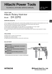
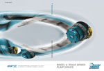
MODEL
PDA-100M
Hitachi
Power Tools
DISC GRINDER
PDA-100M
TECHNICAL DATA
AND
SERVICE MANUAL
P
LIST No. E270
Sept. 2005
SPECIFICATIONS AND PARTS ARE SUBJECT TO CHANGE FOR IMPROVEMENT
REMARK:
Throughout this TECHNICAL DATA AND SERVICE MANUAL, a symbol(s)
is(are) used in the place of company name(s) and model name(s) of our
competitor(s). The symbol(s) utilized here is(are) as follows:
Competitors
Symbols Utilized
Company Name
Model Name
B
BOSCH
GWS6-100
C
MAKITA
9526B
CONTENTS
Page
1. PRODUCT NAME ........................................................................................................................... 1
2. MARKETING OBJECTIVE .............................................................................................................1
3. APPLICATIONS .............................................................................................................................. 1
4. SELLING POINTS .......................................................................................................................... 2
5. SPECIFICATIONS .......................................................................................................................... 5
6. COMPARISONS WITH SIMILAR PRODUCTS ..............................................................................6
6-1. Specification Comparisons ............................................................................................................ 6
6-2. Comparisons in Torque vs. Rotation Speed and Stator Coil Temperature Rise ............................ 7
7. PRECAUTIONS IN SALES PROMOTION .....................................................................................8
7-1. Handling Instructions ..................................................................................................................... 8
7-2. Caution Plate ................................................................................................................................. 8
7-3. Precautions on Usage ................................................................................................................... 8
8. PRECAUTIONS IN DISASSEMBLY AND REASSEMBLY ............................................................ 9
8-1. Disassembly .................................................................................................................................. 9
8-2. Reassembly ................................................................................................................................. 10
8-3. Lubrication Points and Types of Lubricant ................................................................................... 13
8-4. Tightening Torque ........................................................................................................................ 13
8-5. Wiring Diagram ............................................................................................................................ 13
8-6. Insulation Tests ............................................................................................................................ 14
8-7. No-load Current Value ................................................................................................................. 14
9. STANDARD REPAIR TIME (UNIT) SCHEDULES .......................................................................15
Assembly Diagram for PDA-100M
1. PRODUCT NAME
Hitachi Disc Grinder, Models PDA-100M [100 mm (4")]
2. MARKETING OBJECTIVE
The current Model PDA-100D has obtained high evaluation for its highly durable aluminum housing in the Asian
market. However, there is an increasing demand for a durable disc grinder having double-insulated construction
with a high insulation class resin housing. To cope with this demand, we developed the new Model PDA-100M
based on the current Model PDA-100D. The motor of the new Model PDA-100M is more durable than that of the
current Model PDA-100D thanks to the double insulation construction. We aim to expand our market share with
the new Model PDA-100M.
The main improvements are as follows:
1
The motor is so designed that commutation sparks are minimized during operation in order to increase the
service life of the brush, commutator and the motor.
2
The wear resistance of the coil is increased by attaching the protect tape to the coil end at the fan side of the
armature.
3
The iron bearing bushing is adopted as the bearing of the resin housing in order to increase durability of the
housing.
4
Use of thick copper wires increases the motor input and the overload durability owing to reduction of loss.
Please expand the sales of the new Model PDA-100M as well as the conventional Model PDA-100D.
3. APPLICATIONS
Removal of casting fin and finishing of various types of steel, bronze, aluminum, and other metallic materials
and castings
Grinding of welded sections, or sections cut by acetylene torch
Grinding of slate, brick, marble and similar materials
--- 1 ---
4. SELLING POINTS
Convenient spindle lock
Durable motor
Needle bearing for
extended durability
Easy-to-use snap switch
Iron bearing bushing is provided
in the commutator-side bearing
chamber.
High power input: 715 W
PDA-100D: 620 W
B
: 670 W
C
: 710 W
Hitachi original dust proof construction for long service life
against abrasion from dust
Application of adhesive to the commutator hook.
Extended armature wedge.
Protect tape
Vent is resistant to sucking gravel.
Well balanced and ergonomic
design for easy operation
--- 2 ---
Durable motor
The motor of the Model PDA-100M is so designed that commutation sparks are minimized during operation in
order to increase the service life of the brush and the commutator. Table 1 shows the wear ratios of the brush
and the commutator as a result of continuous operation under the same loading conditions as general grinding
operation with respect to the current Model PDA-100D. The service life of the Model PDA-100M is about 1.5
times longer than the current Model PDA-100D and the running cost can be reduced.
Table 1
Maker
HITACHI
B
C
1.0
0.9
1.0
1.0
1.1
1.0
PDA-100M
PDA-100D
Carbon life ratio
1.4
Commutator life ratio
1.5
Model
Hitachi original dust proof construction for long service life against abrasion from dust
The Model PDA-100M is equipped with a motor whose durability is greater than the conventional models by
making the following improvements. The service life of the armature coil is 4 times longer than the
conventional models as a result of the gravel suction test (gravel is forcedly sucked in through the vents of the
tail cover).
The wedges at both ends of the armature coil are extended by 3 to 4.5 mm to protect the portions where the
peripheral speed is the fastest and apt to be disconnected by dust or gravel.
The protect tape covers the coil end at the fan side in order to protect the coil from being worn due to
collision with dust or gravel entered through the air vent and repelled by the fan.
The adhesive coating on the commutator hook prevents a break in the coil due to collision of dust or gravel
with the hook and a short circuit due to deformation of the hook.
Table 2
HITACHI
Maker
Model
Durability ratio
PDA-100M
PDA-100D
4.0
1.0
3 mm to 4.5 mm
--- 3 ---
B
C
0.8
1.0
3 mm to 4.5 mm
New vent construction is adopted to prevent dust or gravel from getting inside.
Model PDA-100D
Model PDA-100M
(Dust or gravel is hard to be sucked in.)
High power input
The motor of the Model PDA-100M is the same size as that of the durable Model PDA-100D. In addition, use
of thick copper wires increases the motor input owing to reduction of loss.
--- 4 ---
5. SPECIFICATIONS
Model
Item
PDA-100M
O.D. 100 mm (4") x Thickness 6 mm (1/4")
Depressed
center
wheel
Dimensions
x I.D. 16 mm (5/8")
Offset amount: 4 mm (5/32")
Max. peripheral speed 4,300 m/min (14,000 ft/min, 72 m/s)
Power source
AC single phase 50 or 60 Hz
Voltage, current and power input
Voltage (V)
110
220
230
240
Current (A)
6.8
3.4
3.3
3.2
Power input (W)
Rotation speed (no-load)
12,000/min
Type of motor
AC single-phase commutator motor
Type of switch
Snap switch
Enclosure
Weight
715
Housing
Glassfiber reinforced polyamide resin (gray)
Tail cover
Glassfiber reinforced polyamide resin (black)
Gear cover
Aluminum alloy die casting (metallic silver)
Packing grand
Aluminum alloy die casting
Net: *1
1.5 kg (3.3 lbs.)
Gross:
2.5 kg (5.5 lbs.)
Packaging
Corrugated cardboard box
Standard accessories*2
Depressed center wheel [Outer dia.100 mm (4") ] ................. 1
Wrench ................................................................................... 1
*1 : Net weight excludes cord, depressed center wheel, wheel nut, wheel washer and wheel guard.
*2 : Standard accessories are subject to change without prior notice.
--- 5 ---
6. COMPARISONS WITH SIMILAR PRODUCTS
6-1. Specification Comparisons
HITACHI
Maker
Model
PDA-100M
PDA-100D
B
C
Wheel diameter
mm
100
100
100
100
No-load speed
/min
12,000
12,000
11,000
11,000
Power input
W
715
620
670
710
Power output
W
430
300
360
370
Max. power output
W
870
800
760
860
L
mm
260
254
265
260
W
mm
76
67
76
67
H
mm
63
60
73
68
P
mm
200
200
191
204
Catalog
kg
1.5
1.7
1.4
1.4
Actual
kg
1.6
2.0
1.4
1.5
Snap
Snap
Snap
Snap
Dimensions
Weight *
Type of switch
P: Perimeter
* Weight excludes cord, depressed center wheel, wheel nut, wheel washer and wheel guard.
--- 6 ---
6-2. Comparisons in Torque vs. Rotation Speed and Stator Coil Temperature Rise
Figure 1 shows comparisons of the rotation speed and the stator coil temperature rise between a competitive
model with respect to torque. Torque represents the magnitude of load, i.e., the amount of pressing force, cutting
depth and forward force in actual cutting jobs. This shows that a powerful motor is less likely to burn out because
it has both a minimum drop of rotation speed even at a greater torque and a lower stator coil temperature rise at
the same torque.
12,000
600
Rotation speed of spindle
500
HITACHI PDA-100M
8,000
400
C
6,000
300
B
B
HITACHI PDA-100D
4,000
200
C
Stator coil temp. rise (k)
Rotation speed of spindle (/min)
10,000
HITACHI PDA-100M
2,000
100
HITACHI PDA-100D
Stator coil temp. rise
: Burn-out point
0
0
0
Load
Torque range
Fig. 1 Comparisons in torque vs. rotation speed and stator coil temperature rise
Figure 1 indicates the following:
1
The motor speed of the Model PDA-100M is higher than that of B, C and Model PDA-100D at the same
torque. This means that the working efficiency of the Model PDA-100M is superior to B, C and Model
PDA-100D.
2
The stator coil temperature rise of the Model PDA-100M is lower than that of B, C and Model PDA-100D
thanks to the improved cooling mechanism and it is equivalent to that of the Model PDA-100D.
This means that the Model PDA-100M has a burn-resistant and tenacious motor.
--- 7 ---
7. PRECAUTIONS IN SALES PROMOTION
In the interest of promoting the safest and most efficient use of the Model PDA-100M disc grinder by all of our
customers, it is very important that at the time of sale, the salesperson carefully ensures that the buyer seriously
recognizes the importance of the contents of the Handling Instructions, and fully understands the meaning of the
precautions listed on the nameplate attached to each tool.
7-1. Handling Instructions
Although every effort is made in each step of design, manufacture and inspection to provide protection against
any hazards, the dangers inherent in the use of any electric tool cannot be completely eliminated. Accordingly,
general precautions and suggestions for the use of electric power tools, and specific precautions and suggestions
for the use of the disc grinders are listed in the Handling Instructions to enhance the safe, efficient use of the tool
by the customer. Salespersons must be thoroughly familiar with the contents of the Handling Instructions to be
able to offer appropriate guidance to the customer during sales promotion.
7-2. Caution Plate
The following caution is listed on the nameplate attached to the main body of each tool.
(1) For Taiwan
7-3. Precautions on Usage
Instruct the customer to pay particular attention to the two points described below.
(1) Use of the side handle (Optional accessory)
When the side handle is used, the customer must be instructed to ensure without fail that the wheel guard is
mounted in the manner so that it protects the operator's hand from coming into contact with the depressed
center wheel.
Pushing button
Side handle
Side handle
Wheel guard
Fig. 2
--- 8 ---
(2) Never press the pushing button while the depressed center wheel is rotating.
If the pushing button (Fig. 2) is pressed while the depressed center wheel is rotating, the spindle will stop
immediately. In such a case, there is a danger that the wheel nut may be loosened, so that the depressed
center wheel flies out unexpectedly and may cause possibly serious injury.
8. PRECAUTIONS IN DISASSEMBLY AND REASSEMBLY
The [Bold] numbers in the descriptions below correspond to the item numbers in the Parts List and the exploded
assembly diagram for Model PDA-100M.
8-1. Disassembly
(1) Disassembly of the armature
1) Remove the Brush Caps [38] and take out the Carbon Brushes [39].
2) Loosen the four Tapping Screws D5 x 25 (Black) [1] which fix the Gear Cover Ass'y [3] to remove the
Armature [7] from the Housing [33] together with the Bearing Holder [6].
3) Loosen the Special Nut M7 [4] which fixes the pinion to remove the pinion.
4) Insert the hooks of the J-204 bearing puller between the Ball Bearing 628VVC2PS2-L [5] and the Bearing
Holder [6] from both sides and fix the hooks with the wing bolts.
5) Place the J-204 bearing puller on a supporting jig and push down on the tip of the armature shaft with a
hand press to remove the Ball Bearing 628VVC2PS2-L [5]. Then remove the Bearing Holder [6].
(2) Disassembly of the dust seal
1) Insert the hooks of the J-204 bearing puller between the commutator and the Dust Seal [11] from both
sides, and fix the hooks with the wing bolts.
2) Place the J-204 bearing puller on a supporting jig and push down on the armature shaft with a hand press
to remove the Dust Seal [11] together with the Ball Bearing 608VVC2PS2L [12]. Replace the Dust Seal
[11] with new one because it is damaged by the removal of the Ball Bearing 608VVC2PS2L [12].
(3) Disassembly of stator (A)
1) Remove the Armature [7] and loosen the Tapping Screw (W/Flange) D4 x 25 (Black) [47] to remove Tail
Cover (B) [46].
2) Loosen the two Machine Screws (W/Washer) M3.5 x 6 [48] that secure the internal wire of the Cord [54]
and Stator (A) [10] to the Switch (1P Screw Type) [49] and loosen the two screws of the Pillar Terminal
[43]. Remove the two internal wires from the Cord [54] and the Pillar Terminal [43].
3) Remove the Tapping Screw (W/Flange) D4 x 40 [37] and the Tapping Screw (W/Flange) D4 x 20 (Black)
[36]. Remove Tail Cover (A) [35] then remove the Earth Terminal [41] from the Housing [33].
4) Disconnect the two internal wires of Stator (A) [10] coming from the Brush Holder [40] of Stator (A) [10].
5) Remove the Fan Guide [8] from the Housing [33].
6) Loosen the Tapping Screw (W/Flange) D4 x 70 [9] securing Stator (A) [10]. Remove Stator (A) [10] from
the Housing [33].
--- 9 ---
(4) Disassembly of the gear
1) Loosen the four Seal Lock Screws (W/Sp. Washer) M4 x 12 [21] that secure the Packing Gland [20] to the
Gear Cover Ass'y [3] and remove the Packing Gland [20] from the Gear Cover Ass'y [3].
2) Remove the Retaining Ring for D11 Shaft [13] that secures the gear to the Spindle [23].
3) Remove the Wave Washer [14] and the gear from the Spindle [23].
8-2. Reassembly
Push the parts together in the reverse order of disassembly, with the precautions given below.
(1) Ensure that the terminals of the stator are not bent or otherwise damaged.
(2) Generously lubricate the teeth of the gear and the pinion with grease. Rub grease onto the teeth with your
fingers so that the grease reaches each tooth bottom. Note that the gear and the pinion may wear faster than
normal if under-lubricated.
(3) Be sure to soak the inner diameter of the Felt Packing [19] with machine oil. Otherwise, its dust-sealing
function will fail to work properly, resulting in earlier damage of the Ball Bearing 6201VVCMPS2L [18].
(4) When replacing the Armature [7] and the Ball Bearing 608VVC2PS2L [12] on the commutator side, press
inward on the Dust Seal [11] while taking care of its direction until the end face of the Dust Seal [11] contacts
against the end surface of the Armature [7] and make sure that Dust Seal [11] cannot be turned freely by
hand. (See Fig. 3).
The Dust Seal [11] is an important element for improved dust protection of the Ball Bearing 608VVC2PS2L
[12]. Be sure to replace with a new one each time.
Armature shaft
Ball Bearing 608VVC2PS2L [12]
Dust Seal [11]
Fig. 3
(5) When connecting the Earth Terminal [41] to the internal wire (the middle wire among three) of the Noise
Suppressor [45], strip the insulation sheath on the internal wire by about 6 mm and press-connect it together
with the Earth Terminal [41] with a clamping tool available on the market.
Solderless connection
Fig. 4
--- 10 ---
Terminal [50]
(6) Mount the Cord [54] according to the following
procedure when replacing the standard cord (cord
85
mm
Bla
ck o
r br
own
armor is integrally molded).
1) Remove the standard cord (cord armor is integrally
Caulking
molded) according to the procedure of 8-1 (3).
2) Strip the coating on the internal wire of the Cord
[54] about 10 mm from the tip and crimp the
Terminal [50] to the brown or black internal wire as
shown in Fig. 5.
Cord [54]
ite
Wh blue
or
mm
40
ed
ipp
r
t
S gth
len m
m
10
Fig. 5
3) Insert the Cord [54] into the Cord Armor D8.8 [51].
4) Cut off the rib for holding the cord of Tail Cover (B)
A --- A
A
[46] with nippers as shown in Fig. 6.
Approximately
2 mm
5) Mount the Cord [54] and the Cord Armor D8.8 [51]
to Tail Cover (A) [35] and secure them with the
Cord Clip [52] and two Tapping Screws (W/Flange)
D4 x 16 [53] as shown in Fig. 7.
6) Mount each internal wire reversing the removal
: Cut off
procedure. Then mount Tail Cover (B) [46] to Tail
Cover (A) [35] and secure them with the Tapping
Screw (W/Flange) D4 x 25 (Black) [47].
Tail Cover (B) [46]
A
Fig. 6
(b) For Singapore and Malaysia
(a) For Taiwan
(c) For other countries
Fig. 7
--- 11 ---
(7) Connect the internal wires of Stator (A) [10] correctly as shown in Fig. 8 and Fig. 9.
(8) Connect each internal wire correctly as shown in Fig. 9 being careful not to put them between the parts.
Internal wire from Cord [54]
Machine Screw (W/Washer) M3.5 x 6 [48]
Guide plate
Switch (1P Screw Type) [49]
OFF side
ON side
: Tail Cover (A) [35]
Machine Screw (W/Washer) M3.5 x 6 [48]
Internal wire from Stator (A) [10]
Internal wire from Noise Suppressor [45]
Fig. 8
Insert the terminal securely then push
and fold the terminal toward the outside
of the housing as much as possible.
Brush Holder [40]
Bottom of the housing
Internal wire coming from
the Noise Suppressor [45]
Fig. 9
(9) When replacing the Gear Cover Ass'y [3], lubricate the needle bearing part with mixed oil.
Mixed oil: A mixture of Hitachi Power Tool Grease No. 2 (Unilube No. 00 Code No. 939302 is recommended)
and turbine oil
Mixture ratio ......... 1:1 (weight ratio)
Quantity ........... 0.5 cc
--- 12 ---
8-3. Lubrication Points and Types of Lubricant
Pinion chamber of Gear Cover Ass'y [3] ..................... Nippeco grease (SEP-3A) 5 g
(Code No. 930035 is recommended.)
Generously rub grease onto the gear and pinion.
Needle bearing ............................................................ Mixed oil 0.5 cc
Mixed oil: Mixture of Hitachi Power Tool Grease No. 2
(Unilube No. 00, Code No. 939302) and
turbine oil
Mixture ratio ................ 1:1 (weight ratio)
8-4. Tightening Torque
Tapping Screws D4 [9] [36] [37] [47] [53] .............................. 2.0
0.5 N•m (20 5 kgf•cm, 1.5
0.4 fb-lbs.)
Seal Lock Screws (W/Sp. Washer) M4 [16] [21] .................... 1.8
0.4 N•m (18 4 kgf•cm, 1.3
0.3 fb-lbs.)
Tapping Screw D5 x 25 (Black) [1] ......................................... 2.9
0.5 N•m (30 5 kgf•cm, 2.2
0.4 fb-lbs.)
Machine Screw (W/Sp. Washer) M5x16 (Black) [25] ............... 1.6
0.4 N•m (16
4 kgf•cm, 1.2
0.3 fb-lbs.)
Special Nut M7 [4] .................................................................. 6.4
1.0 N•m (65 10 kgf•cm, 4.7
0.7 fb-lbs.)
Brush Cap [38] ........................................................................ 0.6
0.2 N•m (6
8-5. Wiring Diagram
(2) For Singapore
Noise
suppressor
(1) For Taiwan
(3) For other countries
Fig. 10
--- 13 ---
2 kgf•cm, 0.4
0.1 fb-lbs.)
8-6. Insulation Tests
On completion of disassembly and repair, carefully measure the insulation resistance and conduct a dielectric
strength test.
Insulation resistance: 7 M Ω or more with 500 V DC megohm tester
Dielectric strength test: AC 4,000 V/1 minute with no abnormalities .................... 220 V --- 240 V products
AC 3,500 V/1 minute with no abnormalities .................... 110 V --- 127 V products
8-7. No-load Current Value
After no-load running for 30 minutes, the no-load current value should be as follows.
Voltage (V)
110
220
230
240
Current (A) max.
2.6
1.2
1.2
1.2
--- 14 ---
9. STANDARD REPAIR TIME (UNIT) SCHEDULES
MODEL
Variable
Fixed
10
20
30
Work Flow
PDA-100M
Switch
Tail Cover (A)
Tail Cover (B)
Cord
Cord Armor
Housing Ass'y
Stator
General Assembly
Armature
Ball Bearing
(628VV)
Bearing Holder
Dust Seal
Ball Bearing
(608VV)
Wheel Guard
Ass'y
Gear Cover
Packing Gland
Ass'y Ball Bearing
Pushing Button
(6201VV)
Lock Pin
Spindle
Gear and
Pinion Set
--- 15 ---
40
50
60 min.
Hitachi Power Tools
LIST NO. E270
ELECTRIC TOOL PARTS LIST
DISC GRINDER
Model PDA-100M
2005
9•5
•
(E1)
1
501
502
2
3
4
5
6
7
13
8
14
9
31
15
10
16
17
18
32
19
11
33
20
12
21
34
22
35
36
23
37
40
24
39
41
38
42
43
25
26
44
27
45
50
46
51
48
49
47
28
52
29
53
54
30
PARTS
ITEM
NO.
1
PDA-100M
CODE NO.
NO.
USED
DESCRIPTION
320-523
TAPPING SCREW D5X25 (BLACK)
4
2
301-944
PUSHING BUTTON
1
3
316-484
GEAR COVER ASS’Y
1
4
301-941
SPECIAL NUT M7
1
5
628-VVC
BALL BEARING 628VVC2PS2-L
1
6
316-480
BEARING HOLDER
1
*
7
360-744C
ARMATURE 110V
1
*
7
360-744G
ARMATURE 220V
1
*
7
360-744E
ARMATURE 230V
1
*
7
360-744F
ARMATURE 240V
1
8
319-898
FAN GUIDE
1
9
319-358
TAPPING SCREW (W/FLANGE) D4X70
2
*
10
340-649C
STATOR (A) 110V
1
*
10
340-649E
STATOR (A) 220V-240V
1
11
315-877
DUST SEAL
1
12
608-VVM
BALL BEARING 608VVC2PS2L
1
13
316-487
RETAINING RING FOR D11 SHAFT
1
14
316-486
WAVE WASHER
1
15
301-943
LOCK PIN
1
16
997-263
SEAL LOCK SCREW (W/SP. WASHER) M4X10
2
17
316-490
BEARING COVER
1
18
620-1VV
BALL BEARING 6201VVCMPS2L
1
19
301-946
FELT PACKING
1
20
316-489
PACKING GLAND
1
21
307-127
SEAL LOCK SCREW (W/SP. WASHER) M4X12
4
22
302-047
WOODRUFF KEY
1
23
316-485
SPINDLE
1
24
301-945
FRINGER
1
25
308-386
MACHINE SCREW (W/SP. WASHER) M5X16 (BLACK)
2
26
301-949
SET PLATE
1
27
301-948
WHEEL GUARD ASS’Y
1
28
320-497
WHEEL WASHER
1
29
316-820
D. C. WHEELS 100MMX4T A36Q (25 PCS.)
1
30
321-795
WHEEL NUT (C)
1
31
321-450
GEAR AND PINION SET
1
HITACHI LABEL
1
HOUSING
1
NAME PLATE
1
32
33
325-140
34
35
325-143
TAIL COVER (A)
1
36
302-086
TAPPING SCREW (W/FLANGE) D4X20 (BLACK)
1
37
306-664
TAPPING SCREW (W/FLANGE) D4X40
1
38
936-551
BRUSH CAP
2
39
999-021
CARBON BRUSH (1 PAIR)
2
REMARKS
INCLUD. 2, 15
INCLUD. 25, 26
40
313-777
BRUSH HOLDER
2
*
41
314-854
EARTH TERMINAL
1
FOR TPE
*
42
980-063
TERMINAL
1
FOR NOISE SUPPRESSOR
*
43
938-307
PILLAR TERMINAL
1
FOR SIN, IND
*
44
959-140
CONNECTOR 50091 (10 PCS.)
1
EXCEPT FOR SIN, IND
*
45
994-273
NOISE SUPPRESSOR
1
FOR TPE
*
46
325-141
TAIL COVER (B)
1
*
46
325-142
TAIL COVER
1
--- 2 ---
FOR SYR
* ALTERNATIVE PARTS
9 -- 05
PARTS
ITEM
NO.
47
CODE NO.
DESCRIPTION
304-035
TAPPING SCREW (W/FLANGE) D4X25 (BLACK)
1
305-499
MACHINE SCREW (W/WASHER) M3.5X6
2
49
955-509
SWITCH (1P SCREW TYPE)
1
50
980-063
TERMINAL
1
48
*
PDA-100M
NO.
USED
REMARKS
FOR CORD
51
953-327
CORD ARMOR D8.8
1
52
937-631
CORD CLIP
1
*
53
984-750
TAPPING SCREW (W/FLANGE) D4X16
2
*
54
500-231Z
CORD
1
*
54
500-409Z
CORD
1
FOR INA, IND
*
54
500-447Z
CORD
1
FOR SYR
*
54
500-468Z
CORD
1
FOR THA
*
54
500-470Z
CORD
1
FOR TPE
9 -- 05
FOR SYR
* ALTERNATIVE PARTS
--- 3 ---
PDA-100M
STANDARD ACCESSORIES
ITEM
NO.
501
*
502
CODE NO.
NO.
USED
DESCRIPTION
REMARKS
313-933
WRENCH
1
302-142
SIDE HANDLE
1 FOR TPE, SIN, KUW
OPTIONAL ACCESSORIES
ITEM
NO.
601
CODE NO.
NO.
USED
DESCRIPTION
302-098
GUIDE BASE
1
602
302-099
WHEEL GUARD FOR 100MM CUT-OFF WHEEL
1
603
984-646
WHEEL NUT FOR 100MM CUT-OFF WHEEL
1
604
323-918
DUST COLLECTION ADAPTER (DISC GRINDER)
1
605
314-053
SANDING DISCS 100MM C-P24 (10 PCS.)
1
606
314-054
SANDING DISCS 100MM C-P30 (10 PCS.)
1
607
314-057
SANDING DISCS 100MM C-P50 (10 PCS.)
1
608
314-059
SANDING DISCS 100MM C-P80 (10 PCS.)
1
609
314-061
SANDING DISCS 100MM C-P120 (10 PCS.)
1
610
314-051
SANDING DISCS 100MM C-P16 (10 PCS.)
1
611
314-052
SANDING DISCS 100MM C-P20 (10 PCS.)
1
612
314-055
SANDING DISCS 100MM C-P36 (10 PCS.)
1
613
314-056
SANDING DISCS 100MM C-P40 (10 PCS.)
1
614
314-058
SANDING DISCS 100MM C-P60 (10 PCS.)
1
615
314-060
SANDING DISCS 100MM C-P100 (10 PCS.)
1
616
954-021
SIDE HANDLE
1
617
935-513
WASHER NUT M10XP1.5
1
618
936-548
WASHER
1
619
936-558Z
RUBBER PAD
1
--- 4 ---
* ALTERNATIVE PARTS
REMARKS
Printed in Japan
(050905N)
9 -- 05