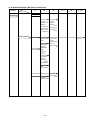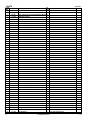
1
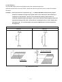
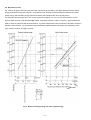
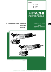
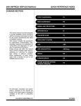
MODEL
NR 83AA2
POWER TOOLS
STRIP NAILER
NR 83AA2
TECHNICAL DATA
AND
SERVICE MANUAL
N
LIST No. E001
May 2001
SPECIFICATIONS AND PARTS ARE SUBJECT TO CHANGE FOR IMPROVEMENT
REMARK:
Throughout this TECHNICAL DATA AND SERVICE MANUAL, a symbol(s)
is(are) used in the place of company name(s) and model name(s) of our
competitor(s). The symbol(s) utilized here is(are) as follows:
Competitors
Symbols Utilized
Company Name
Model Name
R
SENCO
FP650
Y
PASLODE
P350S
CONTENTS
Page
1. PRODUCT NAME ........................................................................................................................... 1
2. MARKETING OBJECTIVE ............................................................................................................. 1
3. APPLICATIONS .............................................................................................................................. 1
4. SELLING POINTS .......................................................................................................................... 1
5. SPECIFICATIONS .......................................................................................................................... 2
5-1. Specifications .................................................................................................................................. 2
5-2. Nail Selection .................................................................................................................................. 3
5-3. Nail Driving Force ........................................................................................................................... 4
5-4. Optional Accessories ...................................................................................................................... 5
6. COMPARISONS WITH SIMILAR PRODUCTS .............................................................................. 6
7. PRECAUTIONS IN SALES PROMOTION ..................................................................................... 7
7-1. Instruction Manual .......................................................................................................................... 7
7-2. Warning Label ................................................................................................................................. 7
7-3. Related Laws and Regulations ....................................................................................................... 8
8. MECHANISM AND OPERATION PRINCIPLE ............................................................................... 9
8-1. Mechanism ..................................................................................................................................... 9
8-2. Interchangeability ........................................................................................................................... 11
8-3. Operation Principle ....................................................................................................................... 12
9. TROUBLESHOOTING GUIDE ..................................................................................................... 16
9-1. Troubleshooting and Correction .................................................................................................... 16
9-2. Regrinding the Driver Blade .......................................................................................................... 18
9-3. Possible Causes and Corrections of Air Leakage ......................................................................... 18
10. DISASSEMBLY AND REASSEMBLY ........................................................................................ 20
10-1. General Precautions in Disassembly and Reassembly .............................................................. 20
10-2. Disassembly and Reassembly of the Output Section ................................................................. 21
10-3. Disassembly and Reassembly of the Control Valve Section ...................................................... 25
10-4. Disassembly and Reassembly of the Driving Section and the Magazine Section ...................... 26
11. INSPECTION AND CONFIRMATION AFTER REASSEMBLY .................................................. 28
12. STANDARD REPAIR TIME (UNIT) SCHEDULES ..................................................................... 29
Assembly Diagram for NR 83AA2
1. PRODUCT NAME
Hitachi Strip Nailer, Model NR 83AA2 [83 mm (3-1/4")]
2. MARKETING OBJECTIVE
The Model NR 83AA2 strip nailer is an upgraded version of the current Model NR 83AA, equipped with the same
output section as the Model NR 83AA that is well reputed with its rapid driving and quick response, and the newly
designed driving and magazine sections. Primary differences from the Model NR 83AA are described below.
(1) Construction of the driving port (nose and piston) is changed to cope with the problem that some of the
commercially available nails are apt to clog.
(2) The magazine is changed from top loading type to rear loading type so that long strip nails such as SENCO
nails can be loaded without folding. In addition, the magazine is lengthened to increase the nail capacity from
82 nails (3.3 mm (0.131 ") dia., HKU) to 86 nails (Paslode F350S: 84 nails).
(3) The body handle of the Model NR 83AA is wound with the grip tape, however, dust adheres to the joints of
tape and it impairs operability. To cope with this problem, a band-type grip rubber is adopted to the Model
NR 83AA2.
(4) In the Model NR 83AA2, the magazine section is simplified and no washer is used to reduce parts count for
easy maintenance.
(5) The claw at the tip of the pushing lever is hardened to increase the wear resistance and the shape of the claw
is changed to prevent slipping even when driving nails in a slanting direction. (The change on the shape of
claw has also been applied to the current Model NR 83AA from the production of May 2000.)
The Model NR 83AA2 is far superior to Paslode F350S and SENCO FP650 in nail driving comfort and ease of
operation. Please expand our market share with the new Model NR 83AA2.
3. APPLICATIONS
Floor and wall framing
Truss build-up, window build-up
Subflooring and roof decking
Wall sheathing
Mobile home and modular housing construction
4. SELLING POINTS
Rubber grip
Rear loading
magazine
Rapid driving and
quick response
--- 1 ---
5. SPECIFICATIONS
5-1. Specifications
NR 83AA2
Model
Driving system
Reciprocating piston type
Operating pressure
5 --- 8.5 kgf/cm2 (70 --- 120 psi, 4.9 --- 8.3 bar) (Gauge pressure)
Driving speed
3 pcs./sec.
Weight
3.8 kg (8.4 lbs.)
Dimensions
(Length x Height x Width)
460 mm x 360 mm x 108 mm
(18-1/8" x 14-3/16" x 4-1/4")
Nail feed system
Spiral spring
Nail capacity
86 to 94 nails
Air consumption
2.5 ltr/cycle at 7 kgf/cm2 (0.088 ft3/cycle at 100 psi) (2.5 ltr/cycle at 6.9 bar)
Air inlet
3/8 NPT thread
Packaging
Corrugated cardboard box
Package dimensions
(Length x Height x Width)
490 mm x 430 mm x 132 mm
(19-5/16" x 16-15/16" x 5-3/16")
Standard accessories
Optional accessories
Hex. bar wrench for M5 screw (Code No. 944458) ....................................
Hex. bar wrench for M6 screw (Code No. 944459) ....................................
Hex. bar wrench for M8 screw (Code No. 872422) ....................................
Eye protector (Code No. 875769) ..............................................................
Sequential trip mechanism kit (Single-shot) (Code No. 876762)
Depth adjustment pushing lever kit (Code No. 883512)
Pneumatic tool lubricant (1 oz oil feeder) (Code No. 877153)
Pneumatic tool lubricant (4 oz oil feeder) (Code No. 872042)
Pneumatic tool lubricant (1 quart can) (Code No. 876212)
--- 2 ---
1
1
1
1
5-2. Nail Selection
The Model NR 83AA2 utilizes D-head (clipped head) nails collated with paper tape.
Applicable nail dimensions are shown below. Please note that screw-type nails cannot be used with the Model
NR 83AA2.
Ensure that nails are as specified in Fig. 1. The Model NR 83AA2 utilizes D-head (clipped
head) nails collated at an angle of 34 degrees which are the same as the nails utilized by a
competitor's model Paslode. However, some D-head nails made by other makers are
collated at a different angle of 26 degrees. Use of such nails will cause clogging of nails and
subsequent damage to the nailer. Also avoid use of misaligned nails or nails collated with a
weak paper tape. It is recommended to use genuine HITACHI nails to ensure satisfactory
driving quality.
Paper tape collated strip nails D-head (clipped head) nails
Minimum
Maximum
7.1 mm
(0.280")
6.8 mm
(0.266")
83 mm (3-1/4")
51 mm (2")
3.3 mm
(0.131")
Max.
4.6 mm
(0.181")
2.9 mm
(0.113")
34˚
Max.
31.7 mm
(1.248")
CAUTION:
Paper tape
Fig. 1 Dimensions of nail
--- 3 ---
3.3 mm x 83 mm nails
(0.131" x 3-1/4")
5-3. Nail Driving Force
Fig. 2 shows by type of wood and nail, the nailer output energy provided by the supply pressure and the nailing
energy required for driving the nail flush. Air pressure which exceeds the intersecting point between the nailer
output energy and the nailing energy required for driving the nail allows the nail to be fully driven.
For example, when driving a nail of 3.3 mm dia. by 83 mm length (0.131" x 3-1/4") into nine sheets of 12 mm
plywood (108 mm thick ) with the Model NR 83AA2, a pressure of about 7.0 bar (7.1 kgf/cm2, 102 psi) allows the
nailer to drive the nail flush with the wood surface. A pressure beyond this value causes the nail head to be driven
below the wood surface. Fig. 2 should be used as reference data because those values vary depending on the
type, moisture content, and grain of wood.
1200
1200
R
NR 83AA2
Y
NR 83AA2
Fig. 2 Required nailing energy and nailer output energy
--- 4 ---
5-4. Optional Accessories
(1) Sequential trip mechanism kit (Single shot) (Code No. 876762)
A sequential trip mechanism kit is provided as an optional accessory for the Model NR 83AA2. By using this
optional accessory, a nail is driven by pressing the push lever first against a workpiece and then pulling the
trigger (single-shot operation), and no nail is driven when pulling the trigger first and then pressing the push
lever against a workpiece. Please recommend the sequential trip mechanism kit to the customers who want to
use it. Salespersons must instruct the customers to read the Handling Instructions attached to the sequential
trip mechanism kit and also the Handling Instructions of the Model NR 83AA2 thoroughly for correct use.
(2) Depth adjustment pushing lever kit (Code No. 883512)
The depth adjustment pushing lever kit is available as an optional accessory of the Model NR 83AA2 to adjust
the nail driving depth (the adjustment procedure is the same as the current Models NR 90AC and NV 65AH).
Salespersons must instruct the customers to read the Handling Instructions attached to the depth adjustment
pushing lever kit and also the Handling Instructions of the Model NR 83AA2 thoroughly for correct use.
--- 5 ---
--- 6 ---
3.7 kg (8.2 lbs.)
465 mm x 330 mm x 114 mm
(18-5/16" x 13" x 4-1/2")
2.6 ltr/cycle
(0.092 ft3/cycle)
84 nails
Top loading
3.8 kg (8.4 lbs.)
425 mm x 360 mm x 108 mm
(16-3/4" x 14-3/16" x 4-1/4")
2.5 ltr/cycle
(0.088 ft3/cycle)
80 nails
Top loading
None
3.8 kg (8.4 lbs.)
460 mm x 360 mm x 108 mm
(18-1/8" x 14-3/16" x 4-1/4")
2.5 ltr/cycle
(0.088 ft3/cycle)
86 nails
Rear loading
None
(Optional accessory: Toolless)
Weight
2.9 mm -- 3.8 mm
(0.113" -- 0.148")
50 mm -- 90 mm
(2" -- 3-1/2")
2.9 mm -- 3.3 mm
(0.113" -- 0.131")
50 mm -- 90 mm
(2" -- 3-1/2")
2.9 mm -- 3.3 mm
(0.113" -- 0.131")
50 mm -- 83 mm
(2" -- 3-1/4")
2.9 mm -- 3.3 mm
(0.113" -- 0.131")
50 mm -- 83 mm
(2" -- 3-1/4")
Dia.
Length
Applicable
nails
Rubber
Racket grip
Rubber
Grip
Leather
With wrench
(360˚)
None
None
With wrench
(Four directions)
With wrench
Rear loading
67 nails
2.7 ltr/cycle
(0.095 ft3/cycle)
381 mm x 362 mm x 106 mm
(15" x 14-1/4" x 4-9/64")
3.8 kg (8.4 lbs.)
5 --- 8.5 kgf/cm2
(70 --- 120 psi)
R
Direction change of
exhaust air
Driving depth
adjustment mechanism
Magazine type
Nail capacity (0.131” nail)
Air consumption at
7 kgf/cm2 (100 psi)
Dimensions
(L x H x W)
With wrench
5.5 --- 8.5 kgf/cm2
(80 --- 120 psi)
5 --- 8.5 kgf/cm2
(70 --- 120 psi)
5 --- 8.5 kgf/cm2
(70 --- 120 psi)
Y
Operating pressure
Model name
NR 83AA
HITACHI
NR 83AA2
Maker
6. COMPARISONS WITH SIMILAR PRODUCTS
7. PRECAUTIONS IN SALES PROMOTION
In the interest of promoting the safest and most efficient use of the Model NR 83AA2 Nailer by all of our
customers, it is very important that at the time of sale the salesperson carefully ensures that the buyer seriously
recognizes the importance of the contents of the Instruction Manual, and fully understands the meaning of the
precautions listed on the Warning Label attached to each tool.
The Model NR 83AA2 Nailer is designed for continuous nail driving (however, some of the Model NR 83AA2 are
designed for single-shot operation only for some destinations). At time of sale, the salesperson must inform the
customer that the sequential trip mechanism kit which can change the Model NR 83AA2 to a single-shot nailer is
optionally available, and recommend it to the customers who want to use it. Refer to the leaflet attached together
with the Instruction Manual for details.
7-1. Instruction Manual
Although every effort is made in each step of design, manufacture, and inspection to provide protection against
safety hazards, the dangers inherent in the use of any pneumatic tool cannot be completely eliminated.
Accordingly, general precautions and suggestions for use of pneumatic tools, and specific precautions and
suggestions for the use of the pneumatic nailer are listed in the Instruction Manual to enhance the safe, efficient
use of the tool by the customer.
Salespersons must be thoroughly familiar with the contents of the Instruction Manual to be able to offer
appropriate guidance to the customers during sales promotion.
7-2. Warning Label
Each Model NR 83AA2 unit is provided with a Warning Label (illustrated below) which lists basic safety
precautions in its use. Carefully ensure that customers fully understand and follow these precautions before using
the tool.
--- 7 ---
The following label is adhered to the Model NR 83AA2 for Europe to prohibit the use of the Model NR 83AA2
standing on a stepladder. Carefully ensure that customers fully understand and follow the precaution before using
the tool.
7-3. Related Laws and Regulations
As nailers and staplers are designed to instantaneously drive nails and staples, there is an ever-present danger of
misfiring and subsequent possible serious injury. Accordingly, close attention in handling is absolutely necessary
at all times. Carefully ensure that the customer is fully aware of the precautions listed in the Instruction Manual
provided with each unit.
While there are no specific safety regulations, there are related items in various general safety regulations with
which the salespersons should be familiar in order to properly advise the customer. Please check your national
and/or local regulations for applicable items. Some applicable items are outlined below.
The U.S.A:
OSHA
1926.102 Eye and face protection
1926.302 Power-operated hand tools
ANSI SNT-101-1993
Portable, Compressed-Air-Actuated,
Fastener Driving Tools-Safety Requirements for
--- 8 ---
8. MECHANISM AND OPERATION PRINCIPLE
8-1. Mechanism
As illustrated in Fig. 4, the Model NR 83AA2 can be generally divided into four sections:
output section, control valve section, driving section and magazine section.
The driving section (nose and piston) and the magazine section have been newly designed though its basic
construction is the same as that of the Model NR 83AA (valve section is common to the Model NR 83AA).
Primary differences from the Model NR 83AA are described below.
Whole body ......................... No washer is used for reduction of parts count.
(The washer of the exhaust cover mounting screw is integrated with the screw.)
Output section ...................
The piston (driver blade) has been newly designed to correspond to the nose
shape. Owing to the enlargement of the driver blade, the driver blade hole in the
piston bumper is also enlarged.
The body handle is wound with a band-type grip rubber instead of the racket-grip
tape. (Conventional grip tape is supplied as a repair part because the grip
rubber cannot be mounted to the body handle by hand.)
The other parts are common to the Model NR 93AA.
Driving section ....................
All the parts have been newly designed.
The nail head supporting portion of the nose is widened as shown in Fig. 3
(same construction as Paslode F-350s) to cope with the problem that some of
the commercially available nails are apt to clog due to the nail supporting portion
is narrow and is apt to wear. Two spring supporters are provided to mount the
depth adjustment pushing lever kit (optional accessory).
Magazine section ................
All the parts have been newly designed.
The magazine section is simpler than the Model NR 83AA for reduction of parts
count.
The magazine is changed from top loading type to rear loading type (same
construction as SENCO FP650).
The magazine can be easily mounted by inserting the magazine into the nose
and securing the handle arm to the body with a screw.
n)
o
rti
g
po
n
rti
Nose
o
pp
u
s .6
ad 0
Nose
Firing gate
e
lh
ai
4
(Nail head supporting portion)
(N
Firing gate
Head of nail
NR 83AA
Fig. 3
--- 9 ---
Head of nail
NR 83AA2
The <Bold> numbers in the figure below correspond to the numbers in "8-3. Operation Principle".
Exhaust Valve < 2 >
Exhaust Vent < 3 >
Piston < 4 >
Exhaust cover
Exhaust piece
Accumulator < 1 >
Output section
Safety valve portion
Cylinder < 6 >
Trigger valve portion
Control valve
section
Grip rubber
Driver Blade < 7 >
Return Air
Chamger < 8 >
Cylinder
Spring < 5 >
Nail stopper
Driving section
Piston
Bumper < 9 >
Nose <10>
Magazine
Magazine section
Firing gate
Nail feeder ass'y
Pushing lever
Fig. 4 Construction
--- 10 ---
8-2. Interchangeability
The driving section and the magazine section are not interchangeable between the Model NR 83AA2 and the
NR 83AA because these sections of the Model NR 83AA2 have been newly designed. The output section and the
control valve section are interchangeable except the following parts.
Part
NR 83AA2
NR 83AA
Body Ass'y [26]
5.7 mm dia. hole
5.7 mm dia. hole
M8 female screw
Piston Bumper (B) [28]
8.3 mm dia.
10 mm dia.
Large hole dia.
Piston [12]
(Driver blade)
Nylock Hex. Socket
Hd. Bolt M8 x 22 [32]
(for mounting the Nose
[33])
Hex. Socket Hd. Bolt
(W/Flange) M6 x 45 [1]
(for mounting the Top
Cover [2])
Sectional view
Sectional view
Nylock Hex.
Socket Hd.
Bolt M8 x 22 [32]
• Short length
• No spring washer
Spring washer
M8 x 25
Nose [33]
Hex. Socket Hd.
Bolt (W/Flange)
M6 x 45 [1]
M6 x 45
Spring washer
Top Cover [2]
Hex. Socket Hd. Bolt
(W/SP. Washer)
M6 x 25 [3]
(for mounting the
Exhaust Cover [4])
Hex. Socket Hd.
Bolt (W/SP. Washer)
M6 x 25 [3]
M6 x 25
Spring washer
Exhaust Cover [4]
--- 11 ---
8-3. Operation Principle
The operation of the Model NR 83AA2 is illustrated and described in Fig. 5 through 8. The circled numbers in the
descriptions correspond to the item numbers shown in the mechanism illustrated in Fig. 4. In Fig. 6 and Fig. 8,
read the descriptions in alphabetical order.
Air pressure is applied to the lower surface of the flanges
located at the center portion of the Cylinder < 6 >, forcing
the cylinder upward. The compressed air is thereby
blocked from the upper end of the cylinder, and no pressure
is applied to the piston.
The Accumlator < 1 > fills with
compressed air.
The trigger and pushing lever are not
operated, and remain closed.
The exhaust vents are opened and no air pressure is
applied to the valve air passage.
Fig. 5 When the compressed air source (air hose) is connected to the nailer
--- 12 ---
Cylinder ring
Compressed air is applied
to the upper side of the
Exhaust Valve < 2 >, forcing
it downward and closing
the Exhaust Vent < 3 >.
Although air pressure is applied to both the
upper and lower sides of the cylinder, the
cylinder is forced downward due to the larger
effective area of the upper side.
Accordingly, the upper portion of the cylinder is
opened, and the compressed air forces the
piston downward.
When the trigger and pushing lever are operated
simultaneously, the safety valve and trigger valve
are opened.
The trigger and pushing lever are operated
simultaneously.
(NOTE)
If either the trigger or pushing lever are
operated individually, compressed air will
not enter the valve air passage, and the
nailer will not function.
When the trigger and pushing lever are
operated simultaneously, the exhaust
vents are closed.
As the piston moves downward, the air below the piston
is forced into the Return Air Chamber < 8 >.
When the piston passes the middle vent, some of the air passes
into the return air chamber. This supplies auxiliary air to ensure
complete return of the piston.
Fig. 6 When the trigger and pushing lever are operated
--- 13 ---
Air pressure is applied in the shaded areas in the
illustration, and each component is held in the
position illustrated.
If the operator's grip is
loosened, air will leak.
At there is no o-ring installed here, a
very small amount of air will leak from
the slight clearance between the
components.
The lower surface of the Piston < 4 > contacts
the Piston Bumper < 9 > and prevents air
leakage. If the upper surface of the Piston
Bumper < 9 > is damaged, some air will leak.
Fig. 7 If the trigger and pushing lever are kept pressed
--- 14 ---
The air pressure on the upper surface of the Exhaust Valve < 2 > is
released, and the exhaust valve is pushed upward by the air pressure
within the cylinder. This opens the Exhaust Vent < 3 >, and the air
pressure in the cylinder is discharged from the nailer.
Air pressure is discharged from the upper end of
the cylinder, and the cylinder is pushed upward by
the air pressure on the lower surfaces of the
flanges and the force of the Cylinder Spring < 5 >.
This closes the upper end of the cylinder, and
blocks compressed air from entering the cylinder.
Valve Exhaust Vent I
Valve Exhaust Vent II
When the trigger is released, the trigger valve closes
and the air pressure within the valve air passage is
discharged through Valve Exhaust Vent I .
In addition, when the pushing lever is lifted from
the wood surface, the safety valve closes, and
the air pressure within the valve air passage is
discharged through Valve Exhaust Vent II .
(The illustration shows both the trigger and
pushing lever released.)
At the time the piston returns, any remaining air pressure at the lower
end of the piston is discharged through the clearance between the
Piston Bumper < 9 > and the Driver Blade < 7 >.
When the air pressure at the upper side
of the piston lowers, the air pressure
within the Return Air Chamber < 8 >
pushes the piston upward.
(NOTE) If the clearance were larger, the
piston would not return: if it were
smaller, driving force would be
decreased.
Fig. 8 When the trigger and/or pushing lever are released
--- 15 ---
9. TROUBLESHOOTING GUIDE
9-1. Troubleshooting and Correction
Problem
1) Nails cannot
be driven.
(
Possible cause
: most-common cause)
<Nails>
The magazine is not loaded
with specified genuine nails.
The magazine is loaded
with abnormal nails (bent
nails, abnormal collation,
other).
<Magazine>
Nail feeder abnormal (burrs,
deformed, damaged).
Ribbon spring abnormal
(fatigued, damaged).
Magazine groove too wide
or too narrow.
Nail rail groove width too
wide or too narrow.
Inspection method
Check if the magazine is
normally loaded with
specified nails.
Check the nail feeding
section for abnormal
conditions (burrs, fatigued,
deformed, damaged).
Remedy
Use specified nails.
Remove the abnormal nails
and load the magazine with
normal nails.
Correct the burred or
deformed portion.
Replace the defective part.
Replace the defective part.
Check if they move
smoothly after putting nails
and check if the nail feeder
oeprates smoothly.
Replace the defective part.
Nail groove in the nose
abnormal (burrs).
Replace the defective part.
Magazine cover abnormal
(deformed, damaged).
Replace the defective part.
Adhesive fragments and
wood chips are on the
magazine, nail feeder or nail
rail.
After removing the adhesive
fragments and wood chips,
apply oil to the nail rail and
magazine.
<Output section: Piston,
driver blade, etc.>
Air pressure too low.
Piston ring worn.
Piston O-ring worn.
Keep the nail feeder ass'y
pulling backward and
perform idle driving. Then
check that the driver blade
returns to its original
position.
Piston bumper abnormal.
Adjust for 5 to 8.5 kgf/cm2
(4.9 --- 8.3 bar, 7 --- 120 psi).
Replace the Piston O-ring.
Replace the piston bumper.
Cylinder ring abnormal.
(dislocated, deformed,
damaged).
Reassemble or replace.
Driver blade abnormal
(deformed, burrs,
damaged).
Touch up or replace.
Cylinder's internal surface
abnormal (deposites of dirt,
worn).
<Pushing lever>
Pushing lever incorrectly
adjusted.
Check if nails can be driven
at 5 kgf/cm2 (4.9 bar, 70 psi).
After removing the dirt,
apply oil or replace.
Check adjustment.
Adjust the protruded amount
within 3.5 0.5 mm
(0.138" 0.02").
--- 16 ---
Problem
2) Nails bent
while being
driven.
(
Possible cause
: most-common cause)
See item 1).
See item 1).
Unspecified nails used.
See item 1).
See item 1).
The material being driven
into is very hard.
Check if the driver blade tip
is abnormally worn.
Check if a nail is bent even
when driven into soft wood.
Air pressure too low.
Replace the part.
Regrind. (See 9-2, "Regrinding
the Driver Blade".)
Unusable because the tool
is not designed for such
usage.
Adjust for 5 to 8.5 kgf/cm2
(4.9 --- 8.3 bar, 70 --- 120 psi).
The material being driven
into is very hard.
Driver blade worn.
Piston O-ring abnormal
(worn, damaged).
Cylinder's internal surface
abnormal (worn, rough).
4) Nails clog the
mechanism.
Remedy
Nails are not fully fed into
the injection port.
Driver blade worn.
3) The nail is
driven into the
material but
the head is
raised above
the surface.
Inspection method
Unspecified nails used.
< Improper nail feed >
See <Magazine> in item 1).
Driver blade worn.
< The driver blade has not
returned completely. >
See <Output section:
Piston, driver blade, etc.>
in item 1).
Drive the nail into soft wood
and check if the head is
raised or not.
Unusable because the tool
is not designed for such
usage.
Check if the driver blade tip
is worn.
Replace the part.
Disassemble the output
section and check the
Piston O-ring and the
internal surface of the
cylinder for abnormal
condition.
Replace the defective part.
Check if the nails are
specified ones.
Use specified nails.
Check if they move
smoothly after putting nails,
and check if the nail feeder
operates smoothly.
See <Magazine> in item 1).
Check if the driver blade tip
is worn.
Replace the part.
Perform idle driving or
actually drive with nails,
and check if the driver
blade has returned
completely.
See <Output section: Piston,
driver blade, etc.> in item 1).
--- 17 ---
Regrind. (See 9-2, "Regrinding
the Driver Blade".)
Replace the defective part.
Regrind. (See 9-2, "Regrinding
the Driver Blade".)
9-2. Regrinding the Driver Blade
The tip of the driver blade should be ground as shown in Fig. 9. To grind with a grinder, gradually grind the tip
while cooling the ground area with water to prevent it from being excessively heated. Excessive grinding will
rapidly reduce the service life of the driver blade. In such a case, replace the driver blade.
Driver blade
Concave
5˚
Grinding surface
Fig. 9
9-3. Possible Causes and Corrections of Air Leakage
Air leakage repair location
A
B
G
E
F
C
D
--- 18 ---
Inspection priorities:
In the table below, possible causes of air leakage and their repair procedures are marked in accordance with the
likelihood of possible failure.
(1) First priority items are marked with an asterisk ( ).
(2) Second priority items (seal portions) are marked with a double circle (
(3) Remaining items are marked with a single circle (
).
). (See Parts List and exploded assembly diagram for part
name and location.)
Cause
Air leak part
When trigger valve/safety valve are OFF
A
Exhaust vent
B
Exhaust cover
Cylinder [17] does not return.
Swollen Cylinder O-ring [16] (Use of
unsuitable oil causes swelling. Advise the
customer to use Shell Tonna Oil T32.)
Deformed Cylinder [17] or Cylinder Guide [22].
Yielded or broken Cylinder Spring [20].
Defective Head Cap and Gasket Set [10]
(worn rubber portion or broken)
Broken Gaskets (C) (F) [8] [6]
Loose Hex. Socket Hd. Bolt (W/Flange)
M6 x 45 [1]
Broken Exhaust Cover [4]
E
Trigger valve
F
Safety valve
G
Cap
Defective Exhaust Valve
[9] (worn, deformed, or
broken)
Deformed Nose [33]
Loose Nylock Hex. Socket
Hd. Bolt M8 x 22 [32]
Nose
D
When trigger valve ON/
safety valve OFF
Loose Hex. Socket Hd. Bolt (W/SP. Washer)
M6 x 25 [3]
Broken Gasket (B) [5]
Damaged seal surfaces of Body Ass'y [26]
and Exhaust Cover [4]
C
Nose
When trigger valve/
safety valve are ON
Damaged Cylinder O-ring [18] or O-ring of
Cylinder Guide [22] (worn, deformed or
broken)
Defective Body Ass'y [26] (worn, corroded or
deformed)
Broken or cracked
Piston Bumper (B) [28]
Deformed Piston [12]
Deformed Nose [33]
Defective Plunger O-ring
[60] (worn, defomred or
broken)
Defective outside
O-ring [52] of Trigger
Valve Bushing [58]
Defective Urethane Ball (C) D7.14 [56]
(damaged or deformed)
Defective ball sheet surface of Trigger Valve
Bushing [58] (damaged, deformed or worn)
Defective Valve Packing [55] (damaged,
deformed or broken)
Soiled or damaged valve packing sheet
surface of Body Ass'y [26]
Incursion of foreign materials
Defective Gaskets (C) (F) [8] [6] (damaged or
yielded)
Deformed or broken Gasket (G) [23]
Defective O-ring [13] or Cylinder O-ring [14]
of the Cylinder Plate [15] (worn, deformed or
broken)
Defective Cylinder O-ring [16] (worn,
deformed or broken
Loose Hex. Socket Hd. Bolt M5 x 18 [40]
Broken Gasket (D) [38]
Defective seal surface of the Body Ass'y [26]
or Cap [39]
--- 19 ---
Air will leak slightly from
the lower portion due to
construction.
Defective outside O-ring
[52] of the Valve Bushing
[51] (worn, deformed or
broken)
Defective plunger O-ring
[49] (worn, deformed or
broken)
Defective Plunger Spring
[48] (deformed or broken)
Defective safety Valve
Bushing [51] (deflected,
deformed or broken)
10. DISASSEMBLY AND REASSEMBLY
The items particularly necessary for disassembly and reassembly are described below. The [Bold] numbers in
the descriptions below correspond to the item numbers in the Parts List and exploded assembly diagram.
[CAUTION]
Before disassembly or reassembly, be sure to remove all nails and disconnect the air hose from the
nailer (with your finger released from the trigger) to exhaust all the compressed air.
10-1. General Precautions in Disassembly and Reassembly
Apply grease (Nippeco SEP-3A, Code No. 930035) to the O-rings and O-rings' sliding portions.
When installing the O-rings, be careful not to damage the O-rings and prevent dirt entry.
Oil required: Hitachi pneumatic tool lubricant
1 oz (30 cc) oil feeder (Code No. 877153)
4 oz (120 cc) oil feeder (Code No. 874042)
1 quart (1 ltr) can (Code No. 876212)
If Gasket (B) [5] is damaged, replace it and check that no air is leaking.
Be especially careful to prevent the entry of foreign particles into the control valve section.
Use the conventional grip tape for repair of the Grip Rubber [37] because the Grip Rubber [37] cannot be
mounted without the specifically designed jig.
Tightening torque for each part
Tightening torque
N•m (kgf•cm, ft-lb)
Bolt
Nylock Hex. Socket Hd. Bolt M8 x 22 ........................... [32]
30.4
2 (310
20, 22.4
1.4)
Nylock Bolt (W/Flange) M8 x 16 .................................... [34]
25.5
1 (260
10, 18.8
0.7)
Hex. Socket Hd. Bolt (W/Flange) M6 x 45 .................... [1]
12.7
0.8 (130
8, 9.4
0.6)
Nylock Bolt (W/Flange) M6 x 12 .................................... [30]
12.7
0.8 (130
8, 9.4
0.6)
Hex. Socket Hd. Bolt (W/SP. Washer) M6 x 25 ............. [3]
9.8
0.8 (100
8, 7.2
0.6)
Hex. Socket Hd. Bolt (W/Flange) M6 x 12 .................... [74]
9.8
0.8 (100
8, 7.2
0.6)
Hex. Socket Hd. Bolt M5 x 18 ....................................... [40]
8.3
0.5 (85
--- 20 ---
5, 6.1
0.4)
10-2. Disassembly and Reassembly of the Output Section
(1) Piston [12], Cylinder [17] and related parts
Tool required:
Hexagon bar wrench (5 mm)
(a) Disassembly (See Figs. 10, 11 and 12.)
Remove the four Hex. Socket Hd. Bolts (W/SP. Washer) M6 x 25 [3], and take off the Exhaust Cover [4].
The Piston [12] can then be taken out.
Next, as illustrated in Fig. 11, screw two of the previously removed Hex. Socket Hd. Bolts
(W/SP. Washer) M6 x 25 [3] into the provided holes on the Cylinder Plate [15].
Gripping these two bolts, simultaneously turn and pull upward to remove the Cylinder Plate [15]. When this
has been accomplished, the Cylinder [17] and other parts which make up the output section can be
removed, as illustrated in Fig. 12.
If it is difficult to remove the Cylinder [17], remove the Nose [33] by referring para. 10-2-(3) procedures, and
push out the Cylinder [17] from the lower part of the main body.
(b) Reassembly
Reassembly can be accomplished by following the disassembly procedures in reverse. However, special
attention should be given to the following items.
Confirm that Gasket (G) [23] is reassembled.
Check that the Base Washer [21] is securely and properly mounted to its position in the Body Ass'y [26].
Then mount the other parts.
Hex. Socket Hd. Bolt
(W/SP. Washer) M6 x 25 [3]
Cylinder Plate [15]
Exhaust Cover [4]
Hex. Socket Hd. Bolt
(W/SP. Washer) M6 x 25 [3]
Piston [12]
Threaded hole
for M6 bolts
Cylinder [17]
Cylinder Plate [15]
Gasket (B) [5]
Body Ass'y [26]
Fig. 10
Fig. 11
--- 21 ---
Cylnder Spring [20]
Piston [12]
Base Washer [21]
Cylinder Guide [22]
Gasket (G) [23]
Cylinder Plate [15]
Cylinder [17]
Body Ass'y [26]
Cylinder Ring [19]
Fig. 12
(2) Head Cap and Gasket Set [10], Exhaust Piece [7] and related parts (See Fig. 13.)
Tool required:
Hex. Socket Hd. Bolt
(W/Flange) M6 x 45 [1]
Hexagonal bar wrench (5 mm)
(a) Disassembly
Top Cover [2]
Remove the Exhaust Cover [4] as described in section
10-2-(1).
Hex. Socket Hd. Bolt
(W/SP. Washer) M6 x 25 [3]
Loosen the three Hex. Socket Hd. Bolts (W/Flange)
M6 x 45 [1] and as illustrated in Fig. 13, remove the
Head Cap and Gasket Set [10], Exhaust Valve [9],
Exhaust Cover [4]
Exhaust Piece [7], Gasket (C) [8] and Gasket (F) [6].
Gasket (B) [5]
(b) Reassembly
Reassembly can be accomplished by following the
Gasket (F) [6]
disassembly procedures in reverse. However, special
Exhaust Piece [7]
attention should be given to the following items.
Gasket (C) [8] and Gasket (F) [6] should be replaced
Gasket (C) [8]
with new genuine Hitachi parts.
Exhaust Valve [9]
Apply the designated grease to the outer circumference
Head Cap and
Gasket Set [10]
of the Exhaust Valve [9] prior to reassembly.
Fig. 13 Disassembly of main body, upper part
--- 22 ---
(3) Piston Bumper (B) [28], Gasket (A) [29] and related parts (See Figs. 14 and 15.)
Tools required
Hexagon bar wrench (5 mm, 6 mm)
Roll pin puller (3 mm (0.118") dia.)
Screwdriver
(a) Disassembly
Pull out the Roll Pin D3 x 30 [43] and remove the Nylock Bolt (W/Flange) M6 x 12 [30] to remove the Guard
[31].
Pull the Nail Feeder Ass'y [69] backward and insert a screwdriver or a rod into the stopper hole for the Nail
Feeder Ass'y [69] as shown in Fig. 15. (This is to prevent the Nail Feeder Ass'y [69] from moving forward
when removing the Magazine [72].)
Remove the Nylock Bolt (W/Flange) M8 x 16 [34] and pull out the entire magazine section backward.
Remove the four Nylock Hex. Socket Hd. Bolts M8 x 22 [32]. Then Piston Bumper (B) [28] and Gasket (A)
[29] can be removed together with the Nose [33].
(b) Reassembly
Disassembly procedures should be followed in the reverse order. Note the following points.
Plunger (B) [54] is apt to come off during disassembly. Be sure to check that Plunger (B) [54] is securely
mounted during reassembly.
Pressing the Magazine [72] against the Nose [33], secure them with the Nylock Bolt (W/Flange) M8 x 16
[34] with a minimum clearance between the Magazine [72] and the Nose [33].
Mount the Roll Pin D3 x 30 [43] without fail.
Roll Pin D3 x 30 [43]
Plunger (B) [54]
Body Ass'y [26]
Nylock Bolt (W/Flange)
M8 x 16 [34]
Piston Bumper (B) [28]
Gasket (A) [29]
Nylock Bolt (W/Flange)
M6 x 12 [30]
Guard [31]
Nylock Hex. Socket
Hd. Bolt M8 x 22 [32]
Nose [33]
Magazine [72]
Fig. 14
--- 23 ---
Nail Feeder Ass'y [69]
Insert a bar such as a screwdriver into this hole.
Fig. 15
--- 24 ---
10-3. Disassembly and Reassembly of the Control Valve Section
Tools required:
Roll pin puller (3 mm (0.118") dia.)
Minus-hd. screwdriver
(a) Disassembly (See Fig. 16.)
Remove the Magazine [72] as described in section 10-2-(3).
Remove the Pushing Lever [46] as described in section 10-2-(3).
With the roll pin puller (3 mm (0.118") dia.), take out the Roll Pin D3 x 30 [43], and remove the Trigger [53],
Trigger Plunger [59] and Plunger (B) [54].
Insert the minus-hd. screwdriver into the groove of the Trigger Valve Bushing [58], and loosen it by turning it
to the left, being careful not to damage the groove.
After removing the Trigger Valve Bushing [58], pull down strongly on the Valve Bushing [51] to remove the
Valve Bushing [51], Plunger (A) [50] and the Plunger Spring [48].
Valve Plate [57]
Plunger Spring [48]
Trigger Valve Bushing [58]
Plunger (A) [50]
Trigger Plunger [59]
Valve Bushing [51]
Roll Pin D3 x 30 [43]
Trigger [53]
Fig. 17
Fig. 16 Disassembly of valve
Plunger (B) [54]
(b) Reassembly
Reassembly can be accomplished by following the
disassembly procedures in reverse. However, special
attention should be given to the following items.
Plunger (A) [50]
Plunger (B) [54]
Be very careful in handling the Plunger Spring [48],
as it can become twisted very easily.
To prevent the two O-rings on the outside of the Valve
Bushing [51] from being damaged when inserted into
Safety Bolt [44]
the body, carefully apply grease to the body hole and
Nut M5 [47]
the outer circumference of the O-rings prior to
assembly.
Nose [33]
(c) Adjustment of the Pushing Lever [46] (See Fig. 17.)
Pushing Lever [46]
The Pushing Lever [46] can be adjusted by loosening
the Nut M5 [47] and turning the Safety Bolt [44].
Perform adjustment to a point where the resistance of
Plunger (B) [54] pushing up Plunger (A) [50] is felt
when the pushing lever is raised. At this point, the
lower end of the Nose [33] should be separated from
the lower end of the pushing lever by
3.5 mm
0.5 mm (.138"
Fig. 17 Pushing lever adjustment
.020").
--- 25 ---
10-4. Disassembly and Reassembly of the Driving Section and the Magazine Section
(1) Nose [33], Pushing Lever [46] and the related parts (See Fig. 18.)
Tool required
Hexagon bar wrench (5 mm)
(a) Disassembly
Perform disassembly according to 10-2-(3) to remove the Nose [33], Pushing Lever [46], and the other
parts.
Remove the Nose Rubber [61] from the Nose [33] by stretching the Nose Rubber [61] with a thin rod.
(b) Reassembly
Disassembly procedures should be followed in the reverse order. Note the following points.
Be careful of the mounting direction of the Nose Rubber [61]. Mount the Nose Rubber [61] aligning with the
shape of the Nose [33].
Hook the Spring [45] in the 3 mm dia. hole of the Nose [33] aligning with the shape of the Pushing Lever
[46]. (The Nose [33] has two 3 mm dia. holes, one is for hooking the Spring [45] and the other is for the
depth adjustment pushing lever kit (optional accessory).)
Do not insert a roll pin into the other 3 mm dia. hole. This hole is for the depth adjustment pushing lever kit
(optional accessory).
Nose Rubber [61]
Nylock Hex. Socket
Hd. Bolt M8 x 22 [32]
Safety Bolt [44]
Spring [45]
Nose [33]
Pushing Lever [46]
Nut M5 [47]
3 mm dia. hole
Fig. 18
--- 26 ---
(2) Magazine [72], Nail Feeder Ass'y [69] and the related parts (See Fig. 19.)
Tool required
Hexagon bar wrench (5 mm )
(a) Disassembly
Perform disassembly according to 10-2-(3) to remove the entire magazine section.
Remove a screwdriver or a rod from the the stopper hole for the Nail Feeder Ass'y [69]. Then the Nail
Feeder Ass'y [69], Ribbon Spring [70] and Needle Roller D4 x 20 [71] can be removed from the front of the
Magazine [72].
Remove the three Hex. Socket Hd. Bolts (W/Flange) M6 x 12 [74]. Then Handle Arm [36], Nail Stopper
[75] and Magazine Cover [64] can be removed together with the other parts.
The Nail Rail [62] that is press-fitted into the Magazine [72] has a protrusion at the rear end to prevent
coming off. Tap at the front of the Magazine [72] using a hammer and a bar being careful not to scratch the
parts.
(b) Reassembly
Disassembly procedures should be followed in the reverse order. Note the following points.
Insert the Nail Rail [62] from the rear of the Magazine [72] and press-fit the Nail Rail [62] into the Magazine
[72] by tapping with a wooden hammer so that the protrusion of the Nail Rail [62] becomes flush with the
rear end of the Magazine [72].
Hook the hook of the Ribbon Spring [70] on the Magazine [72] then mount the Nail Feeder Ass'y [69] to the
Magazine [72]. Slide the Nail Feeder Ass'y [69] backward and insert a screwdriver or a rod into the stopper
hole for the Nail Feeder Ass'y [69] as shown in Fig. 15.
Press the mounting surface of the Nail Stopper [75] against the Magazine [72] and slide it backward until
the "A" portion fits into the concave portion of the Magazine Cover [64] then secure them with the bolt. At
this time, mount the Sleeve [63] without fail.
Concave portion
Nylon Nut M6 [35]
Sleeve [63]
Magazine Cover [64]
Convex portion
Rear
Nail Rail [62]
Hooking portion
A
Nail
Stopper
[75]
[74] Hex. Socket
Hd. Bolt (W/Flange)
M6 x 12
Ribbon Spring [70]
Hook
Nail Feeder Ass'y [69]
Magazine [72]
Front
Needle Roller
D4 x 20 [71]
Fig. 19
--- 27 ---
(3) Nail Feeders (A) [65], (B) [67] and the related parts (See Fig. 20.)
Tool required
Roll pin puller (4 mm (0.157") dia.)
(a) Disassembly
Fix the Nail Feeder Ass'y [69] using a V-block and pull out the Roll Pin D4 x 40 [66] from the top using a roll
pin puller (4 mm (0.157") dia.). Then Nail Feeder (A) [65], Nail Feeder (B) [67] and Feeder Spring [68] can
be removed.
(b) Reassembly
Disassembly procedures should be followed in the reverse order. Note the following points.
Insert the Roll Pin D4 x 40 [66] into Nail Feeder (B) [67]. Insert the Feeder Spring [68] into the hole of the
Nail Feeder (B) [67] and compress the Feeder Spring [68] until it is engaged with the protrusion of Nail
Feeder (A) [65].
Protrusion
Roll Pin D4 x 40
[66]
Nail Feeder (A)
[65]
[69] Nail Feeder Ass'y
Hole
[67]
[68]
Nail Feeder (B)
Feeder Spring
Fig. 20
11. INSPECTION AND CONFIRMATION AFTER REASSEMBLY
Check that Plunger (B) [54] and Trigger Plunger [59] move smoothly.
Check that there is no air leakage from each part.
While driving nails with an air pressure of 4.5 kgf/cm2 (63 psi), check that there is no idle driving and bending
of nails.
Recheck the tightening torque of each screw.
Check that Pushing Lever [46] slides smoothly.
Check that the machine will not operate only by actuating Trigger [53]. Also check that the machine will not
operate only by depressing Pushing Lever [46].
--- 28 ---
12. STANDARD REPAIR TIME (UNIT) SCHEDULES
MODEL
Variable
Fixed
10
20
30
Top Cover
Exhaust Cover
Gasket x 3
Exhaust Piece
Exhaust Valve
Head Cap and
Gasket Set
Tail Cover
Magazine
Magazine
Cover
Ribbon Spring
Nail Feeder
Ass'y
Pushing Lever
Spring
Cylinder Plate
Cylinder
Cylinder Spring
O-ring x 7
Piston Bumper
(B)
40
50
60 min.
Work Flow
NR 83AA2
General Assembly
Plunger Spring
Plunger (A)
Valve Bushing
Trigger
Plunger (B)
O-ring x 3
Valve Packing
O-ring x 2
Trigger Valve
Bushing
Trigger Plunger
Piston
O-ring (1AP-48)
Adjustment
(Cylinder, Body)
--- 29 ---
Adjustment
(Valve, Return
Valve)
Body Ass'y
LIST NO. E001
PNEUMATIC TOOL PARTS LIST
STRIP NAILER
Model NR 83AA2
2001• 3 • 15
(E1)
501
502
503
504
506 507
505
1
2
76
3
34
20
35
4
5
77
78
79
80
81
41
40
36
39
38
21
13
55
56
6
7
8
52
22
57
37
48
13
23
9
12
24
42
26
43
52
44
53
45
54
30
15
31
61
75
74
74
32
66
19
73
70
33
18
35
62
16
17
64
47
28
14
43
63
46
27
29
60
51
25
13
59
50
10
11
58
49
71
65
69
67 68
72
PARTS
ITEM
NO.
*
CODE NO.
NR 83AA2
NO.
DESCRIPTION
USED
HEX. SOCKET HD. BOLT (W/FLANGE) M6X45
3
1
883-509
2
877-330
TOP COVER
1
3
883-507
HEX. SOCKET HD. BOLT (W/SP.WASHER) M6X25
4
4
877-324
EXHAUST COVER
1
5
877-325
GASKET (B)
1
6
877-329
GASKET (F)
1
7
877-328
EXHAUST PIECE
1
8
877-854
GASKET (C)
1
9
878-417
EXHAUST VALVE
1
10
877-307
HEAD CAP AND GASKET SET
1
11
877-368
O-RING (1AP-48)
1
12
883-510
PISTON
1
13
877-316
O-RING (S-90)
3
14
877-312
CYLINDER O-RING (I.D 63.1)
1
15
877-318
CYLINDER PLATE
1
16
877-313
CYLINDER O-RING (I.D 79.3)
1
17
877-810
CYLINDER
1
18
877-314
CYLINDER O-RING (I.D 69.3)
1
19
877-317
CYLINDER RING
1
20
877-321
CYLINDER SPRING
1
21
877-322
BASE WASHER
1
22
877-310
CYLINDER GUIDE
1
23
877-327
GASKET (G)
1
24
878-184
WARNING LABEL
1
25
878-183
WARNING LABEL
1
FOR FRA
26
883-506
BODY ASS’Y
1
INCLUD.37
27
877-315
CYLINDER O-RING (I.D 63.9)
1
28
883-511
PISTON BUMPER (B)
1
29
877-334
GASKET (A)
1
30
882-974
NYLOCK BOLT (W/FLANGE) M6X12
1
31
883-493
GUARD
1
32
883-492
NYLOCK HEX. SOCKET HD. BOLT M8X22
4
33
883-490
NOSE
1
34
883-505
NYLOCK BOLT (W/FLANGE) M8X16
1
35
963-837
NYLON NUT M6
3
36
883-504
HANDLE ARM
1
37
38
877-331
GRIP RUBBER
1
GASKET (D)
1
39
878-311
CAP
1
40
949-658
HEX. SOCKET HD. BOLT M5X18 (10 PCS.)
3
41
872-035
42
DUST CAP
1
NAME PLATE
1
43
949-866
ROLL PIN D3X30 (10 PCS.)
2
44
875-650
SAFETY BOLT
1
*
45
877-365
SPRING
1
*
45
878-423
SPRING
1
*
*
REMARKS
46
883-494
PUSHING LEVER
1
47
949-555
NUT M5 (10 PCS.)
1
48
875-643
PLUNGER SPRING
1
49
874-436
O-RING (P-4)
1
50
877-338
PLUNGER (A)
1
--- 2 ---
* ALTERNATIVE PARTS
(SUPPLIED WITH ITEM NO.602,603)
FOR FRA
FOR TPE,FRA,USA,CAN
FOR TPE,FRA,USA,CAN
3 -- 01
PARTS
*
*
NR 83AA2
ITEM
NO.
CODE NO.
51
877-337
VALVE BUSHING
52
875-638
O-RING (S-12)
53
876-203
TRIGGER
1
54
877-339
PLUNGER (B)
1
NO.
REMARKS
USED
1
FOR TPE,FRA,USA,CAN
DESCRIPTION
3
55
878-734
VALVE PACKING
1
56
875-645
URETHANE BALL (C) D7.14
1
57
875-644
VALVE PLATE
1
58
877-335
TRIGGER VALVE BUSHING
1
59
878-121
TRIGGER PLUNGER
1
60
874-820
PLUNGER O-RING
1
61
883-491
NOSE RUBBER
1
62
883-496
NAIL RAIL
1
63
883-499
SLEEVE
1
64
883-497
MAGAZINE COVER
1
65
883-502
NAIL FEEDER (A)
1
66
949-688
ROLL PIN D4X40 (10 PCS.)
1
67
883-501
NAIL FEEDER (B)
1
68
883-441
FEEDER SPRING
1
69
883-500
NAIL FEEDER ASS’Y
1
70
883-503
RIBBON SPRING
1
71
943-364
NEEDLE ROLLER D4X20
1
72
883-495
MAGAZINE
1
LABEL
1
73
FOR TPE,FRA,USA,CAN
INCLUD.65-68
74
984-443
HEX. SOCKET HD. BOLT (W/FLANGE) M6X12
3
75
883-498
NAIL STOPPER
1
*
76
882-408
PLUNGER SPRING (S)
1
FOR SEQUENTIAL TRIP MECHANISM TYPE
*
77
874-436
O-RING (P-4)
1
FOR SEQUENTIAL TRIP MECHANISM TYPE
*
78
882-409
PLUNGER (S)
1
FOR SEQUENTIAL TRIP MECHANISM TYPE
*
79
882-411
BUSHING (S)
1
FOR SEQUENTIAL TRIP MECHANISM TYPE
*
80
882-412
ROD SPRING (S)
1
FOR SEQUENTIAL TRIP MECHANISM TYPE
*
81
882-410
ROD (S)
1
FOR SEQUENTIAL TRIP MECHANISM TYPE
3 -- 01
* ALTERNATIVE PARTS
--- 3 ---
NR 83AA2
STANDARD ACCESSORIES
ITEM
NO.
CODE NO.
501
872-422
HEX. BAR WRENCH 6MM
1
502
944-459
HEX. BAR WRENCH 5MM
1
503
944-458
HEX. BAR WRENCH 4MM
1
NO.
USED
DESCRIPTION
REMARKS
504
875-769
EYE PROTECTOR
1
*
505
877-153
PNEUMATIC TOOL LUBRICANT (30CC)
1
FOR FRA
*
506
882-413
CAUTION TAG
1
FOR USA,CAN
*
507
882-414
LEAFLET
1
FOR USA,CAN
OPTIONAL ACCESSORIES
ITEM
NO.
CODE NO.
601
876-762
SEQUENTIAL TRIP MECHANISM KIT
1
602
881-768
GRIP TAPE (A)
1
603
880-407
TAPE
1
--- 4 ---
NO.
USED
DESCRIPTION
* ALTERNATIVE PARTS
REMARKS
Printed in Japan
(010315N)
3 -- 01