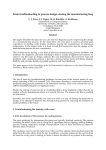
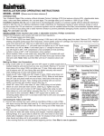
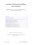
1
FOREWORD
The purpose of this manual is to assist you in operating and maintaining your
Flail mower. Read it carefully before operating and maintaining the Flail mower, it
furnishes the specifications, construction, instructions and also the maintenance.
Some information may be general in nature due to unknown and varying
conditions. However, through experience and these instructions, you should be
able to develop operating procedures suitable to your particular situation.
“Right” and “left” as used throughout this manual are determined by facing the
direction the machine will travel when in use.
Please kindly note that the contents of this operations manual may be a little bit
different from the Flail mower that you actually purchase. This is due to the
continuous improvement and development of the series Flail mower, however,
the specifications and structure of the Flail mower shall be subject to change
without notice.
Thank you very much for purchasing our products. We cordially welcome all the
suggestions, advises and comments on our products from the users and dealers
so that we may make necessary improvements on our products continuously to
meet the requirements of every specific market.
We strived to make this operations manual as correct as possible. However, we
do not guarantee the accuracy or recentness of the information herein due to
having translated the manual to English. We assume no liability for errors or
omission.
1
CONTENTS
CHAPTER Ⅰ SAFETY INFORMATION ............................................................................... 3
1.1 Safety First .............................................................................................................. 3
1.2 Safety Signs ............................................................................................................ 4
CHAPTER Ⅱ SPECIFICATIONS ......................................................................................... 5
2.1 Brief Introduction ..................................................................................................... 5
2.2 Specifications and Parameters for Flail Mower........................................................ 6
CHAPTER Ⅲ OPERATION................................................................................................. 7
3.1 Checking Before Operating ..................................................................................... 7
3.2 Adjusting the Height................................................................................................. 8
3.3 Regulating the Tension of Driving Belt ..................................................................... 9
3.4 Staring up ................................................................................................................ 9
CHAPTER Ⅳ SERVICE AND MAINTENANCE .................................................................. 11
4.1 Service................................................................................................................... 11
4.2 Maintenance .......................................................................................................... 12
4.3 Storage .................................................................................................................. 13
4.4 Operation After Storage ......................................................................................... 14
CHAPTER Ⅴ ILLUSTRATED PARTS CATALOGUE .......................................................... 15
5.1 Flail Mower Assembly (EF95-EF155) .................................................................... 15
5.2 Gearbox assembly (EF95-EF155) ......................................................................... 17
5.3 Blade Axle and Transmission Parts (EF95-EF155)................................................ 18
5.4 Flail Mower Assembly(EF165-175) ........................................................................ 19
5.5 Gearbox assembly(EF165-175)............................................................................. 21
5.6 Blade Axle and Transmission Parts(EF165-175) ................................................... 22
2
CHAPTER Ⅰ SAFETY INFORMATION
PLEASE NOTE
Make sure all potential operators of this equipment review this manual and
all safety messages contained within.
1.1 Safety First
Read this service manual before using the machine.
This safety alert symbol indicates important safety messages in this
manual. When you see this symbol, carefully read this message that
follows and be alert to the possibility of personal injury or death.
This machine is designed for pulverizing grass and short bramble, and shall be used in the
indicated purpose. You take the responsibility if the machine is used in any other purposes.
For safety of personnel and good performance of the machine, you shall check the
performance of the machine and the tractor before starting the machine.
All persons and animals shall keep away the machine when you start it.
The operator shall not put on too loose clothes during operating the machine.
Do not touch the rotor when the machine rotates.
Keep away the machine when it moves.
When the tractor and the machine are moving on the road, always keep the machine off.
Before repairing the machine, stop all movable parts and the tractor, keep the key with
yourself.
Always keep the machine in a good state, if necessary, repair or change the defective parts.
Don’t use the machine to transport personnel.
Don’t modify the machine.
3
Pay attention to the sharp and pointed parts during repairing the machine.
All protective parts shall be guaranteed to be in good state before starting the machine.
Don’t leave the tractor when moving the machine; and always take away the key of the
tractor with you.
The machine shall be operated in the recommended speed.
Don’t stay between the tractor and the machine.
Don’t start the machine in a closed place (due to the smoke from the tractor).
1.2 Safety Signs
1.2.1 Care of Safety Signs
1.
Keep safety signs clean and legible at all times.
2.
Replace safety signs that are missing or have become illegible.
3.
If a component with a safety sign(s) affixed is replaced with a new part, make sure new
safety sign(s) are attached in the same locations as the replaced components.
4.
Safety signs are available from your authorized Distributor or Dealer Parts Department or the
factory.
1.2.2 Safety Signs locations
The types of safety signs and locations on the equipment are shown in the illustrations that
follow. Good safety requires that you familiarize yourself with the various safety signs, the
type of warning and the area, or particular function related to that area, that requires your
SAFETY AWARENESS.
4
CHAPTER Ⅱ SPECIFICATIONS
2.1 Brief Introduction
The series Flail mower is designed for pulverizing grass and short bramble, and shall be
used in the indicated purpose.
The Flail mower consists of a rotating shaft with many blades attached to it. The blades cut
the grass while traveling over the working area. Rotational power to the shaft is provided by
the tractor PTO through the gearbox in the center of the machine.
The Flail mower attaches to the 3 point hitch on the tractor.
Fig. 2.1 Main components of the Flail mower
1. Blade axle
2. Blade axle cover
3. Combined fender
4.Supporting frame
5. Gearbox assembly 6. Suspension bracket 7. Transmission shaft 8. Belt wheel and belt
5
2.2 Specifications and Parameters for Flail Mower
Model
Dimensions (L×W×H) (mm)
Structure weight (kg)
Cutting width (mm)
2
Working efficiency (m /h)
EF95
EF105
EF115
1050×687×722
1150×687×722
1250×687×722
115
130
145
929
1029
1129
2500-7500
3000-8000
3300-9000
Input rotating speed (RPM)
540
6-tooth Φ35mm Rectangular spline
PTO spline size
Power required (HP)
16-20
20-30
20-30
Model
EF125
EF135
EF145
1350×687×722
1450×687×722
1550×687×722
160
175
190
1229
1329
1429
3700-9800
4000-10600
4300-11400
Dimensions (L×W×H) (mm)
Structure weight (kg)
Cutting width (mm)
2
Working efficiency (m /h)
Input rotating speed (RPM)
540
6-tooth Φ35 mm Rectangular spline
PTO spline size
Power required (HP)
20-35
25-35
25-35
Model
EF155
EF165
EF175
1650×687×722
1750×687×722
1850×687×722
210
235
255
1529
1629
1729
4600-12240
4900-13000
5200-13800
Dimensions (L×W×H) (mm)
Structure weight (kg)
Cutting width (mm)
2
Working efficiency (m /h)
Input rotating speed (RPM)
PTO spline size
Power required (HP)
6
540
6-tooth Φ35 mm Rectangular spline
30-40
30-40
30-40
CHAPTER Ⅲ OPERATION
CAUTION: Be familiar with the machine before starting. Read
this manual carefully to learn how to operate the
machine safely and how to set it to provide
maximum field efficiency.
3.1 Checking Before Operating
ATTENTION: Only use universal joint conforming to CE
standard and protect them properly.
Before operating the machine, the following areas should be checked off:
1.
Before starting up the machine, check and Lubricate all grease points, all lubricated
parts inside the machine.
2.
Use only an agricultural tractor of horsepower within limits of the machine specified.
3.
Check that the machine is properly attached to the tractor. Be sure retainers are used
on the mounting pins.
4.
Be sure extra weights are mounted on the front of the tractor.
5.
Check the oil level in the gearbox. Add as required.
6.
Check that the tractor PTO shaft turns freely and that the machine driving shaft can
telescope easily.
7.
Check the blades. Be sure they are not damaged or broken and swing freely in their
mount. Repair or replace as required.
8.
Check and tighten the blade bolts.
9.
Check for entangled material in all rotating parts. Remove this material.
10.
Install and secure all guards, doors and covers before starting.
11.
Before installing the universal joint, the tractor and the machine motor shall be
stopped and the key be taken away. The universal joints shall be installed in good
state, with proper protective parts.
12.
The chain on the protective parts of the universal joint shall be guaranteed in good
condition, in case, automatic rotation occurs.
13.
All other persons shall leave the ground before connecting the driving power from the
7
tractor. Keep the output of the tractor at 540 RPM.
14.
Before cleaning, repairing and lubricating the machine, stop the motor and take away
the key with you.
15.
When the universal joint is not connected with the tractor, they must be connected
again through the frame to protect the joint from damaging.
16.
Don’t approach the machine when the machine runs.
3.2 Adjusting the Height
In order to conduct a precise work, the machine shall be operated according to the
recommended cutting height.
For saving fuel and power, and reducing the wear of the machine, the cutting height must be
regulated correctly.
When regulating the working height, loosen the screw (1), remove the screws (2) on both
sides; regulate the roller height (see following drawing); fix the parts on the set position. The
lowest hole is the highest working height; put the screws (2) into the set hole; tighten screw
(1) and screws (2).
2
1
8
3.3 Regulating the Tension of Driving Belt
ATTENTION: The machine shall always stand still for
regulating the tension.
Remove the drivng betl cover. Loosen screws 1 2 3 4. and adjust screw 1. Tighten the
screws 1 2 3 4 . Put back the driving belt cover.
1
2
3
4
3.4 Staring up
Before starting the machine, control and adjust the following items:
z
z
z
z
Tension of trapezoidal driving belt.
Oil level of gear.
Point of lubrication
All bolts, nuts and screws.
9
Working
Position
Moving
Position
In order to keep the machine stable, install the supporting frame on the machine when the
machine is stopped (see above drawing).
ATTENTION: When transferring the moving state of the machine
to the working state, do not stand between the
machine and the tractor.
The machine coupling is equipped with 3 pins so that the machine can be coupled with all
tractors with universal coupling with 3 pins. Each telescopic pole on the machine can be
adjusted properly according to the type of the tractor. Keep the Flail mower away the tractor
with a certain distance. The universal joint shall be tense and the largest distance in the
closed state shall be 5/10 cm.
Moving the lifting arm, and putting it between axes, insert the joint pins and fix them with
pins. Fix the lifting arm with chain and tensioning device so as to prevent lateral movement
of the machine. Connect the universal joint to the PTO shaft of the tractor on the side of the
tractor. In any event, it cannot produce a collision in any position. While connecting 3 points,
pay attention to that the PTO shaft of the tractor shall be parallel with the ground. It is very
important to keep the machine driving axle and the PTO shaft of the tractor in parallel.
The machine shall be lifted from the ground before moving the machine.
10
CHAPTER Ⅳ SERVICE AND MAINTENANCE
4.1 Service
4.1.1 FLUIDS AND LUBRICANTS
1. Grease:
Use multi-purpose lithium based grease.
2. Gear Box Oil:
Use N46 drive &hydraulic dual-purpose oil or equivalent for all operating conditions.
Each Gearbox Capacity: 0.85 liter
3. Storing Lubricants:
Your machine can operate at top efficiency only if clean lubricants are used. Use clean
containers to handle all lubricants. Store them in an area protected from dust, moisture
and other contaminants.
4.1.2 GREASING
z
Use a hand-held grease gun for all greasing.
z
Wipe grease nipple with a clean cloth before greasing, to avoid injecting dirt and grit.
z
Replace and repair broken nipple immediately.
z
If nipples will not take grease, remove and clean thoroughly. Also clean lubricant
passageway. Replace nipple if necessary.
11
4.2 Maintenance
ATTENTION: All maintenance, repairing, cleaning and lubricating
shall be conducted when the tractor and motor are
stopped and the key is taken away.
By following a careful service and maintenance program for your machine, you will enjoy
many years of trouble-free operation.
The period recommended is based on normal operating conditions. Severe or unusual
conditions may require more frequent maintenance.
4.2.1 8 HOURS OR DAILY MAINTENANCE
z
z
Check and screw all nuts and bolts in connection parts.
Check the blade and fixing parts every day and replace the damaged parts if they are
found damaged. Don’t install damaged, worn and unbalanced blade. New sleeve shall
be used to replace the worn fixing parts on the blade.
NOTE:
The operator shall put on gloves and use suitable tools before changing blade.
z
z
z
Check the oil in gearbox. Fill them up to line if it’s necessary.
Press butter in each oil nipple three to five times.
Clean the implement; take away all grass and mud.
IMPORTANT: Check the oil level only when the unit is cold and
the machine is on the level.
4.2.2 SEASON MAINTENANCE
z
z
z
z
12
Check the machine as below beside the terms of daily maintenance.
Check the oil in gearbox; replace it if it is bad.
Check the bearings of blade spindles whether mud and water have been enter because
oil seals are damaged, if it’s so, disassemble and clean them and replace them if it is
necessary. And then press butter into them.
Check the distance between bearings and gears. Adjust them if it’s necessary.
4.2.3 ANNUALLY MAINTENANCE
z
z
z
z
z
z
z
Cleaning mud and grass on the machine thoroughly.
Check all clearance between bearings and gears if you have replaced them. Please run
it without load for 3-5 minutes.
Check and clean blade axles. Replace oil seals and press butter into them.
Check all blades, replace then if they are wear-out or damaged.
Repair the side skirts; let them to original technical condition. Replace damaged or
broken protective devices.
Remove the driving shaft from the machine. Pull the machine driving shaft apart. Check
and replace any components that are damaged or worn. Install the driveline on the
machine. The machine driving shaft should telescope easily and the guard turn freely
on the shaft
Let the oil in gearbox drain out thoroughly. Check and clean it. Fill new gear oil up to the
dedicated oil level.
The oil shall be drained off after 50 hours of using time. Then the oil shall be drained off
every 250 hours. One time every year at least.
The draining procedure is as follows: remove the draining bolt under the gear box, so that
the oil drains off. After the oil is drained off, put back the cover and fill the gear oil up to the
dedicated oil level.
ATTENTION: Don’t forget to disconnect the generator cable and
batteries when welding on the machine, while the
machine is coupled with the tractor.
4.3 Storage
The machine inside and outside shall be cleaned carefully so as to avoid corrosion.
Don’t spray water on the rolling bearing if you clean the machine with high pressure sprayer.
Check and clean the universal joint, driving belt press roller, or replace them if they are not in
good state.
Spread oil on all parts required.
Recoat the parts rubbed and damaged for anti corrosion.
Store the machine in a dry, level area. Support the frame with planks if require.
13
4.4 Operation After Storage
Before the machine is started up, check the following items regularly:
Check oil level and add it if not enough.
Check and tighten all screws and nuts;
Check the regulated state of the machine.
Check the blade state.
Check the air hole on the gearbox. If it is blocked, clean or open the hole with compressed
air.
Don’t spread oil or grease on the driving belts. If there is oil or grease on the belts, wipe the
belts, in case the belt sliding and wearing occur.
ATTENTION: Check the machine every 10 hours. Repair the
damaged parts or replace the blade according to
the manufacturer’s recommendation, to keep the
machine balancing.
Check all tightening parts and replace them if necessary.
Don’t remove the protective parts on some points and protect the machine.
ATTENTION: In the case of vibration, stop the machine and
check the blade. If the blade breaks or is
damaged, replace it with same type of the blade.
If the machine vibrates still, send the machine to
the authorized repairer.
14
CHAPTER Ⅴ ILLUSTRATED PARTS CATALOGUE
The manual contains a parts list for your machine. It is divided into major sections, which
correspond to the groups shown in the Table of Contents and the accompanying illustration.
The first page of each major section lists the contents of that section, each of which consists
of exploded views and related tabular listings.
When ordering parts
Always give your dealer the Model of your machine to assist him in ordering and obtaining
the correct parts. Use the exploded view and tabular listing of the area of interest to exactly
identify the required part.
5.1 Flail Mower Assembly (EF95-EF155)
15
Flail
Mower
Ser.No
16
Assembly
Part No
Name
and
Specification
Quantity
1
SL100.00.023
Hanging Plate (left)
1
2
SL100.00.024
Mud shield
1
3
SL100.00.025
roller
1
SL100.00.165
Copper sheath
2
4
SL100.01.001
Gearbox
1
5
SL100.00.101
Rear fender
1
6
SL100.00.115
Guard shade
1
7
GB 5783-86
Hex.head bolt M10×60
1
8
SL100.00.112
Guard cover
1
9
SL100.00.015
Gearbox seat
1
10
SL100.00.022
Hanging plate(right)
1
11
SL100.00.021
Belt cover
1
12
GB 97.1-85
Plain washer 12
1
13
GB 5780-86
Hex.head bolt M10×80
1
14
200.56.011
Lock pin
3
15
SL100.00.106
spacer
2
16
SL100.00.104
pin
2
17
SL100.00.019
Pin weldment
1
18
SL100.00.020
Suspension plate(right)
1
19
SL100.00.018
Bracket
1
20
SL100.00.107
Fixing plate
1
21
GB 6170-86
Hex. nut M10
10
22
GB 93-87
Spring lock washer 10
8
23
SL100.00.017
Hook
1
24
GB 5783-86
Hex. head bolt M10×30
8
25
SL100.00.016
Suspension plate(left)
1
26
SL100.00.105
Bent pin
1
27
SL100.00.014
Supporting frame
1
28
SL100.00.011
Combined fender
1
29
SL100.00.013
Blade axle cover
1
30
GB 5783-86
Hex. head bolt M8×20
3
31
GB 6170-86
Hex. nut M8
3
Remarks
5.2 Gearbox assembly (EF95-EF155)
Gearbox Assembly
Ser.No
1
2
3
4
5
6
7
8
9
10
11
12
13
14
15
16
17
18
19
20
21
22
23
Part No
GB 5783-86
GB 93-87
SL100.01.107
SL100.01.108
GB 13871-94
GB/T 276-94
SL100.01.109
SL100.01.110
SL100.01.111
SL100.01.106
SL100.01.112
GB 894.1 - 86
SL100.01.114
SL100.01.113
12.37.149
200.38.024
SL100.01.105
GB1096-79
SL100.01.104
SL100.01.103
SL100.01.102
SL100.01.101
Name and Specification
Hex. head bolt M8×30
Spring lock washer 8
Bearing cover
Paper gasket
Oil seal 35×50×8
Bearing 6207
Adjusting shim
Key
Pressure spring
Input shaft
Bevel gear
Blocked patch 35
Retainer
Case
Combined seal washer
Oil drain plug
Blocked patch
Output shaft
Key 10×45
Spacer sleeve
Paper gasket
Bearing cover
Connected sleeve
Quantity
8
8
1
1
2
4
4
1
2
1
1
1
1
1
1
1
1
1
1
1
1
1
1
Remarks
17
5.3 Blade Axle and Transmission Parts (EF95-EF155)
Blade Axle and Transmission Parts
Ser.No
Part No
and
Specification
Quantity
1
GB1096-79
Key 10×30
1
2
SL100.00.113
Transmission shaft
1
3
UC205-Z
Bearing with flange 90207
3
Grease nipple M8
1
4
18
Name
5
GB 93-87
Spring lock washer
8
14
6
GB 5783-86
Hex. head bolt M8×25
14
7
SL100.00.109
Outer swellable sleeve
2
8
SL100.00.110
Inner swellable sleeve
2
9
GB 93-87
Spring lock washer 6
6
10
GB 70-85
Hex. head bolt M6×25
6
11
SL100.00.114
Belt wheel (large)
1
12
GB
Belt
2
13
SL100.00.012
Blade axle
1
14
SL100.00.103
Spacer
36
15
SL100.00.102
Blade
36
16
GB 6170-86
Hex. nut
17
GB 5780-86
Hex. head bolt M12×80
18
18
SL100.00.111
Belt wheel (little)
1
19
SL100.00.108
Sleeve
1
M12
18
Remarks
5.4 Flail Mower Assembly(EF165-175)
Ser. No.
Part No
Name and Specification
Quantity
1
EF175-0006
Gearbox
1
2
EF175-1023
Shaft Sleeve
1
3
EF175-1022
Shaft
1
4
DIN 6885
Key 10*65
1
5
GB13912
Hex. head bolt
6
GB93-87
Spring lock washer
7
EF175-0004
Shaft tube
8
GB5783-86
Hex. head bolt
9
GB848
Washer
10
GB982
Nylon lock nuts
11
GBIT70.3-2000
Screw M8*30
12
GB848
Nylon lock nuts
13
EF175-0007
Mud shield
1
14
EF175-0002
Roller
1
15
GB5783-86
Hex. head bolt
16
GB848
Plain washer
17
REACH-04
18
EF175-1024
D35
M8*35
8
Remarks
4
4
1
M12*30
12
12
30
M12
34
10
M18
M12*100
12
2
1
6
Swell Sleeve
2
Belt wheel (large)
1
19
Ser. No. Part No
20
Name and Specification
Quantity
19
EF175-1025
Belt wheel (little)
1
20
EF175-0005
Belt cover
1
21
GB5783-86
Hex. head bolt
22
GB93-87
Spring locked washer
23
GB934
Hex. head bolt
24
GB934
Hex. nut M16*1.5
1
25
EF175-0001
Blade axle cover
1
26
EF175-0016
Bracket
1
27
EF175-0013
Suspension plate (left)
1
28
EF175-0014
Suspension plate (right)
1
29
EF175-0015
Supporting fender
1
30
EF175-1043
Axle
1
31
GB97.1
Plain washer
32
GB879-6
Pin
2
33
EF175-1041
Combined fender
19
34
EF175-1050
Bent pin
1
35
EF175-1046
Pin
2
36
EF175-1047
Sleeve
2
37
EF175-1048
“R” Pin
3
38
EF175-1033
Plate
4
39
EF175-0008
Bracket
1
40
EF175-1065
hook
1
41
EF175-0009
Welding
plate(left)
1
42
EF175-0010
Welding
plate(right)
1
43
GB91-86
Split pin 3*35
2
44
EF175-1027
Hanging plate(left)
1
45
EF175-1028
Hanging plate(right)
1
46
GB5783-86
Hex. head bolt
24
47
UC205
Bearing UC205
M12*40
12
M16(1.5)*65
12
M12*35
2
8
1
18
2
Remarks
5.5 Gearbox assembly(EF165-175)
.
Ser. No.
Part No
Name and Specification
Quantity
1
EF175-2001
Gear box
1
2
EF175-2002
Bevel gear
1
3
EF175-2003
Adjusting shim
2
4
UC6007
Bearing 6007
2
5
GB893-86
Blocked patch
6
EF175-2004
Input shaft
1
7
EF175-2005
Key
2
8
EF175-2006
Cover
1
9
Oil seal
42
35*80*8
1
1
10
GB5783-86
Hex. head bolt
11
EF175-2007
Adjusting shim
2
12
EF175-2004
Input shaft
1
13
EF175-2005
Key
2
14
EF175-2006
Cover
1
15
Oil seal
M12*35
35*80*8
8
1
16
GB5783-86
Hex. head bolt
17
EF175-2007
Adjusting shim
2
Oil seal
1
18
19
EF175-2011
Spring
72*35
M12*35
Remarks
8
2
21
5.6 Blade Axle and Transmission Parts(EF165-175)
Ser. No.
Part No
Name and Specification
13*965
Quantity
1
13*965
Belt
2
UC207
Bearing
3
EF175-0003
Sleeve
1
4
EF175-0004
Blade axle
1
5
GB982
Nylon lock nut
6
EF175-1020
Sleeve
28
7
EF175-1040
Blade
28
8
GB5783-86
Hex. head bolt
Remarks
3
UC207
M12
M12*75
2
28
28
The information contained in this operations manual is a general introduction only. The
information contained herein may be modified at any time, for any reason. Modification may
affect the details or specifications of the product described in this manual. Therefore, users –
dealers must include the manufacturing date and serial number when placing an order for
spare parts and components. Thanks.
22
23