1
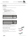
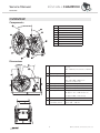
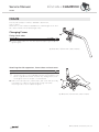
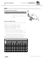
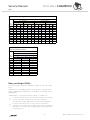
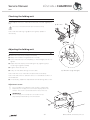
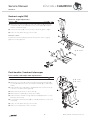
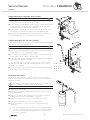
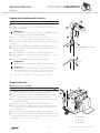
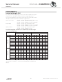
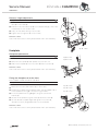
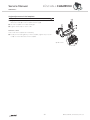
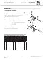
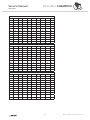
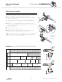
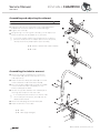
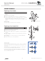
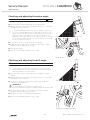
KÜSCHALL CHAMPION DEALER: Keep this manual. The procedures in this manual MUST be performed by a qualified technician. Service Manual ©2014 Küschall AG All rights reserved. Republication, duplication or modification in whole or in part is prohibited without prior written permission from Küschall AG. Trademarks are identified by ™and ®. All trademarks are owned by or licensed to Küschall AG or its subsidiaries unless otherwise noted. Service Manual KÜSCHALL CHAMPION TABLE OF CONTENTS GENERAL....................................................................................................................... 4 Introduction 4 Spare parts and adaptations 4 Tightening Allen screws 4 Torque 5 Checks 5 Identifying and alleviating malfunctions 5 OVERVIEW.....................................................................................................................6 Components 6 Dimensions 6 FRAME.............................................................................................................................7 Changing Frame 7 SEAT............................................................................................................................... 8 Fitting seat cover to frame 8 Front seat height (SHv) 8 Rear seat height (SHh) 9 Checking the folding unit 10 Adjusting the folding unit 10 BACKREST....................................................................................................................11 Tension adjustable backrest 11 Backrest height (RH) 14 Backrest angle (RW) 15 Push handles / backrest telescopes 15 Replacing foldable push handles 17 Stabilisation bar 17 FOOTRESTS.................................................................................................................18 Lower leg length (UL) 18 Footplate 19 SIDE PARTS..................................................................................................................21 Clothes-guard assembly 21 Mud guard assembly 23 Assembling and adjusting the siderest 24 Assembling the tubular armrest 24 FRONT WHEELS......................................................................................................... 25 Replacing a front wheel 25 Replacing a front wheel fork 25 Checking and adjusting the castor angle 26 Checking and adjusting the drift angle 26 Shift supporter on the frame 27 REAR WHEELS............................................................................................................ 28 Rear wheels, repositioning 28 Wheel camber, adapter sleeves 28 Adjusting the removable axle 28 Distance sleeves 29 Adapterplate, adjustment to folding unit or assembly of new adapter plate 29 BRAKES........................................................................................................................ 30 Fitting / adjusting the parking brake 30 Antitipper / Transit wheels 31 Tipper aid / Cane holder 32 Fitting the pelvic belt 32 3 © Küschall AG, Switzerland | 2015-09 Service Manual KÜSCHALL CHAMPION GENERAL Introduction This service manual is part of the instructions and contains the technical information for servicing, configuring and repairing a küschall® wheelchair. WARNING! Danger of accident and severe injuries. If the wheelchair is improperly set it can cause accidents and severe injuries. ▸▸Changes to the wheelchair may only be carried out by the dealer. To guarantee the required safety and reliability, all wheelchairs must be comprehensively checked once a year. In part, assembly and adjustment require extensive experience. For this reason, the following assembly instructions have been split into three categories: Requirement Symbol Easy – technical understanding required Intermediate – specialist knowledge required Difficult – specialist wheelchair assembly knowledge and experience required The required tools and their respective sizes are listed above each instruction. The instructions include information on the torques with which the respective screw connections must be tightened. Adhering to the given torques requires the use of a torque spanner. Tools Symbol Allen key à 2x3, 4, 5, 6 Phillips screwdriver Ò2 Straddle spanner Socket spanner/ring spanner 19, 11 8, 10, 14, 22 Spare parts and adaptations All spare parts can be purchased from küschall®'s Customer Services. An electronic spare parts catalog is available by logging onto www.kuschall.com. Only original spare parts may be used. Installing additional adaptations to a küschall® wheelchair requires the prior written approval of Küschall AG. Tightening Allen screws Allen keys are not designed for greater forces. When tightening or loosening an Allen screw, it is therefore advisable to apply force to the nut to prevent the hexagon socket from being damaged. Tightening and loosening Turn the nut with a socket spanner (only use a straddle spanner if there is insufficient space) and merely hold the screw tight with the Allen key. 4 © Küschall AG, Switzerland | 2015-09 Service Manual KÜSCHALL CHAMPION Tightening and loosening if there is no nut If an Allen screw is directly screwed into a screw thread, the screw must be tightened using an Allen key. i not worn. Ensure that the Allen key is of good quality and Torque All screw connections must be tightened with the torques specified in the following instructions. Checks Visual check Check all components for cracks, especially the areas around joints and welded seams. Checking the screw connections Check all bolts with the torques specified in the instructions regularly, and adjust if required. CAUTION! Several screw connections have been secured with thread locking adhesive. If these are opened, they must be secured again using new thread locking adhesive. Liquid high-strength and low-strength adhesives are available. For torque entries notice shall be made whether an adhesive and which adhesive needs to be used. Identifying and alleviating malfunctions Malfunction The wheelchair will not move in a straight line Possible cause Measure Incorrect tire pressure in a rear wheel Correct tire pressure One or more spokes broken Replace defective spoke(s) Spokes unevenly tensioned Tighten excessively loose spokes Dirty or damaged wheel bearings Clean or replace bearings Bearing block of castor fork is not vertical Align bearing block vertically Front wheels not set to the same height Rear wheels not parallel or axes not aligned The wheelchair tips backwards too easily Position the front wheels in such a way that they touch the ground at the same time Adjust the prestress load on the scissor mechanism and/or the trail Rear wheels have been fitted too far forward Fit rear wheels further back Backrest angle too great Reduce backrest angle Seat angle too great Mount the adapter plate lower on the side profile Mount the smaller castor fork Incorrect tire pressure in one or both rear wheels The brakes engage poorly or asymmetrically Brake setting incorrect Correct tire pressure Correct brake setting Roll resistance is too great Insufficient tire pressure in the rear wheels Correct tire pressure Rear wheels are not parallel Ensure that the rear wheels are parallel The front wheels wobble when moving fast The front wheel is stiff or stuck The wheelchair is very difficult to unfold Insufficient tension in the front wheel bearings block Lightly tighten the nut in the bearings block axle Handling seems imprecise Front wheel is worn flat Replace front wheel Dirty or damaged bearings Clean or replace the bearings The backrestcover is too tight Loosen the backrestbands a little The scissor mechanism is not closed properly If required, remove dirt from scissor mechanism The scissor mechanism is misaligned Realign the scissor mechanism 5 © Küschall AG, Switzerland | 2015-09 Service Manual KÜSCHALL CHAMPION OVERVIEW OVERVIEW Components A Backrest B Rear wheel with handrim C Quick release axle D Folding mechanism E Front wheel fork with front wheel F Footrest G Frame H Seat I Mudguard Dimensions A Seat depth 340 – 480 mm, in increments of 20 mm (AL / TI) 400 – 460 mm, in increments of 20 mm (C) B Backrest angle 76°/80,5°/85°/89,5°/94° C Knee-to-heel length 220 – 500 mm, in increments of 10 mm (AL / TI) 300 – 340 / 400 – 500 mm, in increments of 10 mm (C) D Seat height front 450 – 540 mm, stepless adjustable E Seat height rear 390 – 490 mm, stepless adjustable F Backrest height 300 – 465 mm, in increments of 15 mm G Total length 75°: approx. 825 – 1190 mm (AL / TI) 90°: approx. 775 – 1140 mm (AL / TI) 85°: approx. 800 – 1165 mm (C) H Seat width 340 – 480 mm, in increments of 20 mm I Total width Seat width plus 160 – 240 mm Total width, folded approx. 280 – 340 mm AL = Aluminium / TI = Titanium / C = Carbon 6 © Küschall AG, Switzerland | 2015-09 Service Manual KÜSCHALL CHAMPION FRAME FRAME The küschall Champion frame is available in aluminium, titan or carbon. Aluminium or titan frames are available with frame angles of 75° and 85°, carbon frames with a frame angle of 85° Changing Frame Fitting frame tubes Difficulty: Tools: à 4 10 Fit both frame tubes into the side supporters A using bolts B and tighten lightly. B à 13 Nm / 10 Nm with carbon frame Attaching the side supporters, frame tubes and seat cover Difficulty: Tools: à 5 10 The purpose of the threaded connection through the frame i mounting holes is to provide additional fixing. The frame is thus easier to guide and is better secured. Any misalignment of the toe angle of the front wheels is counteracted. Attach the side supporters, frame tubes, seat cover and optionally, the holders for siderests using bolts F through the frame mounting holes on both sides and tighten. F à 13 Nm / 10 Nm with carbon frame 7 © Küschall AG, Switzerland | 2015-09 Service Manual KÜSCHALL CHAMPION SEAT SEAT Fitting seat cover to frame 10 Tools: à 3, 4 Difficulty: Fit seat cover to side supports and frame on both sides using bolts A and B. A à 13 Nm / 10 Nm with carbon frame B à 5 Nm Front seat height (SHv) The following possibilities are available to adjust the front seat height (SHv): - Replace the front wheel with a larger or smaller one, Chap. Front wheels; Replacing a front wheel. - Replace the front fork with a larger or smaller one, Chap. Front wheels; Replacing a front wheel fork. - Move the side support on the frame, Chap. Front wheels; Shift supporter on the frame. i necessary to adjust the rear seat height correspondingly. It must be ensured that the rear wheels are parallel after changing i the Adjusting the front seat height changes the seat angle. It may be front seat height. If required, they must be readjusted, Chap. Rear wheels; Adjustment of rear wheel parallelism. After adjusting the front seat height the verticality of the castor pins need to be checked and adjusted if neccessary, Chap. Front wheels; Checking and adjusting the alignment of the supporters. Front seat height (SHv) per frame size, castor fork and front wheel SHv [mm] 540 530 520 510 500 490 480 470 460 450 Aluminium / Titan frame 75° (long frame) (short frame) ST 40-48 ST 34-38 ST 40-48 ST 34-38 3'' 4'' 5'' 3'' 4'' 5'' 3'' 4'' 5'' 8 3'' 4'' 5'' © Küschall AG, Switzerland | 2015-09 Service Manual KÜSCHALL CHAMPION SEAT Front seat height (SHv) per frame size, castor fork and front wheel SHv [mm] 540 530 520 510 500 490 480 470 460 450 Aluminium / Titan frame 85° (long frame) (short frame) ST 40-48 ST 34-38 ST 40-48 ST 34-38 3'' 4'' 5'' 3'' 4'' 5'' 3'' 4'' 5'' 3'' 4'' 5'' Front seat height (SHv) per frame size, castor fork and front wheel SHv [mm] 540 530 520 510 500 490 480 470 460 450 Carbon frame 85° (long frame) ST 40-48 3'' 4'' - 5'' - Rear seat height (SHh) The following possibilities are available to adjust the rear seat height (SHh): - Adjustment of the adapter plate to the folding unit, Chap. Rear wheels; Adapterplate, adjustment to folding unit or assembly of new adapterplate. - Replacement of the rear wheel with a larger or smaller one. i the rear seat height, If required, they must be readjusted, It must be ensured that the rear wheels are parallel after changing Chap. Rear wheels; Adjustment of rear wheel parallelism. i changing the rear seat height, If required, they must be readjusted, It must be ensured that the the castor pins are vertical after Chap. Front wheels; Checking and adjusting the alignment of the supporters. 9 © Küschall AG, Switzerland | 2015-09 Service Manual KÜSCHALL CHAMPION SEAT Checking the folding unit Tools: à 5 Difficulty: The bolt A of the scissor mechanism must be checked regularly for play. A à 4 Nm The scissor mechanism must open and close easily. Check that the retaining rings B are sitting well, replace if neccessary. Adjusting the folding unit Difficulty: Tools: Ã3 16 Remove the end-stop nut C from bolt E. Apply new thread locking adhesive on bolt E. Screw the end-stop nut completely on the bolt again, but do not tighten. Adjust the end stop F of the folding unit by tightening resp. loosening the grub screw D. Tighten the end-stop nut. C à 13 Nm (high-strength) Carry out the same settings on both sides. Check that the scissor mechanism opens and closes easily. Check the seat cover for sufficient tension in unfolded condition of the wheelchair. If neccessary, repeat the steps above until all settings are correct. Adjustment screw i Depending on the play the screw head is slightly above the The screw A in the folding unit has the aim to reduce play. surface. The screw is secured and cannot become loose. IMPORTANT! Do not modify the screw A as it can result in a less easy folding and unfolding of the wheelchair. 10 © Küschall AG, Switzerland | 2015-09 Service Manual KÜSCHALL CHAMPION BACKREST BACKREST Tension adjustable backrest IMPORTANT! Risk of damage to the wheelchair. A too tight band installation may cause damage to the backrest when unfolding the wheelchair. ▸▸Make sure that the backrest bands are only adjusted in unfolded condition of the wheelchair. Tension adjustable backrest with push handles standard Push- Interhandle mediate tube Velcro straps without stabilisation bar Velcro straps with stabilisation bar RH [mm] 300 S S L S+M S 315 S S L S+M S 330 S L L S+M 345 S L L 2xM 360 S L L 2xM 375 S L L 2xM M 390 S L L 2xM M 405 L L L S+2xM S S+L L 420 L L L S+L S S+L L 435 L L L S+L S S+L L 450 L L L S+L S M+L L 465 L L L M+L S M+L L S not S=5cm L=10cm M possible S M M L Tension adjustable backrest with foldable push handles teles- InterVelcro straps copic mediate without stabilitube tube sation bar Velcro straps with stabilisation bar RH [mm] 300 S S L S+M S 315 S S L S+M S 330 S L L S+M S 345 S L L 2xM M 360 S L L 2xM 375 S L L 2xM 390 S L L 2xM M 405 L L L S+2xM L 420 L L L S+L L 435 L L L S+L L 450 L L L S+L L 465 L L L M+L L not possible M M 11 S M L © Küschall AG, Switzerland | 2015-09 Service Manual KÜSCHALL CHAMPION BACKREST Tension adjustable backrest without push handles RH [mm] Teles- Inter- Velcro straps copic mediate without tube tube stabilisation bar Velcro straps with stabilisation bar 300 S S L S+M S 315 L S L S+M S 330 L S L S+M 345 L S L 2xM 360 L S L 2xM 375 L L L 2xM M 390 L L L 2xM M 405 L L L S+2xM S S+L L 420 L L L S+L S S+L L 435 L L L S+L S S+L L 450 XL L L S+L S M+L L 465 XL L L M+L S M+L L S=5cm L=10cm S not possible M S M M L Tension adjustable backrest with rearset push handles height adjustable RH [mm] Teles- Inter- Velcro straps Velcro copic mediate without straps with tube tube stabilisation stabilisation bar bar 300 S S L 2xS S 315 L S L 2xS S 330 L S L 2xS 345 L S L S+M 360 L S L S+M 375 L L L S+M M 390 L L L 2xM M 405 L L L 2xM S M L 420 L L L 2xM S M L 435 L L L 2xM S S+M L 450 XL L L 2xM S S+M L 465 XL L L L S S+M L S=5cm L=10cm S not possible M S M M L 12 © Küschall AG, Switzerland | 2015-09 Service Manual KÜSCHALL CHAMPION BACKREST Tension adjustable backrest with push handles, height adjustable RH [mm] Push- Backrest- Velcro straps Velcro handle tube without straps with stabilisation bar stabilisation bar 300 S L S+M S 315 S L S+M S 330 M L S+M 345 M L 2xM M L 2xM M L 2xM M M L 2xM M L L S+2xM S S+L L L L S+L S S+L L 435 L L S+L S S+L L 450 L L S+L S M+L L 465 L L M+L S M+L L 375 390 405 420 Standard push handle 360 S not M possible M 13 S=5cm L=10cm S M L © Küschall AG, Switzerland | 2015-09 Service Manual KÜSCHALL CHAMPION BACKREST Backrest height (RH) In order to adjust the backrest height (RH), the backrest tubes have to be fixed in a different position or they have to be exchanged. B A Standard backrest cover, height adjustment Difficulty: Tools: Ã3 8 Push the backrest cover so that bolt and nut on the backrest tube are revealed. Remove bolt and nut A. Adjust the backrest tube B to the required height then insert the screw A into the closest hole and tighten it again. Carry out the same setting on both sides. Reposition the backrest cover correctly. A à 7 Nm Tension adjustable back, height adjustment Difficulty: Tools: Ã3 8 Remove the backrest cover A. Slide the backrest straps either up or down to locate the fixing B à 7 Nm B bolt B. Remove bolt and nut B. Adjust the backrest tube to the required height then insert the screw B into the closest hole and tighten it again. A Carry out the same setting on both sides. Reposition the backrest cover. i may have to be inserted or removed and a larger/smaller backrest In the case of major changes of the backrest height (RH), bands cover may be necessary. 14 © Küschall AG, Switzerland | 2015-09 Service Manual KÜSCHALL CHAMPION BACKREST Backrest angle (RW) Backrest, angle adjustment Difficulty: 10 Tools: Ã4 Remove the lower bolt A from the side supporter B and move the backrest C to the required position. The spacer D remaines fixed in the latch bolt E. Insert bolt and nut A into the closest hole and tighten it again. Carry out the same setting on both sides. Function control: The backrest must fold easily and the ratchet bolt must sit tightly against the side supporter. A à 13 Nm Push handles / backrest telescopes Push handle / telescopic tube replacement Difficulty: Tools: Ã3 8 Ò2 C à 4 Nm Remove the backrest cover A. Remove the screws C holding the uppermost backrest band B F à 7 Nm (or standard backrest cover) to the push handles E (or telescopic tubes). Slide the backrest straps D (or standard backrest cover) either up or down to locate the fixing bolt F. Remove bolts and nuts on both sides F. Remove push handles E (or telescopic tubes). Slide new push handle through backrest band B and fix it on the backrest with bolt F. Fix the upmost backrest band B (or standard backrest cover) with screws C. Carry out the same setting on both sides. Reposition the backrest cover correctly. 15 © Küschall AG, Switzerland | 2015-09 Service Manual KÜSCHALL CHAMPION BACKREST Height adjustable integrated push handles Difficulty: Tools: Ã3 8 Ò2 Fit the backrest tube A corresponding to the desired backrest height (RH) on both sides using the bolts B. Slide the backrest bands C corresponding to the desired backrest height (RH) and, if required, the end band D (or the standard backrest cover) over the backrest tube A. Slide the push handle F into the backrest tube A on both sides and secure it at the desired height using the clamp bolt G. Secure the end band D (or the standard backrest cover) to the backrest tube A on both sides using the screws E. B à 7 Nm E à 4 Nm Height adjustable rear set push handles These push handles can only be used in combination with adjustable backrests, not with standard backrests. Difficulty: Tools: Ã3 8 Ò2 Fit the intermediate tube A on both sides using the bolts B. Slide the backrest bands C corresponding to the desired backrest height (RH) onto the intermediate tube A. Fit the telescopic tube D corresponding to the desired backrest height (RH) on both sides using the bolt E. Slide the holder F and the sleeve G onto the telescopic tube D and secure it using the screws H. For the minimum backrest height, the holder of the rear set push handle must be fitted to the intermediate tube A. In this case, the sleeve G is not required. Slide the end band I onto the telescopic tube D and secure it on both sides using the screws J. B à 7 Nm E à 7 Nm H à 13 Nm J à 4 Nm Replacing the handle An adhesive (e.g. hair spray) is used in these instructions. When applied to the handle, this substance works as a lubricant and as an adhesive once dry. After drying, the adhesive used must be able to resist a pull-off force of 750 N. If in doubt, contact Küschall® AG. Difficulty: 0 Remove the old handle. 0 Remove any residue (residual adhesive, grease, dust) from the push handle tube. 0 Apply a thin layer of hair spray all over the surface of the push handle tube onto which the handle is to be slid. 0 Apply a thin layer of hair spray to the inside of the handle. 0 Slide the new handle onto the push handle tube. 0 Move the handle into the correct position (grooves facing upwards). i short one, the push handle tube must be shortened by 35 mm. If a long handle has been fitted and this is to be replaced with a The push handle tube must be replaced when switching from a short to a long handle. 16 © Küschall AG, Switzerland | 2015-09 Service Manual KÜSCHALL CHAMPION BACKREST Replacing foldable push handles Difficulty: Tools: Hole punch pliers 6 mm, à 3, 4 0 Remove the old foldable push handle. 0 Pull down the backrest cover F on the telescopic tube, until its hole B is uncovered. IMPORTANT! Make sure that the threaded insert E (part no. 1580450) supplied with the new push handle is used for assembly. 0 Place the threaded insert E in the telescopic tube. 0 Punch a hole through the backrest cover with a distance of 10 mm from the upper egde, using hole punch pliers (see graphic below). 0 Slide the new foldable push handle A onto the telescopic tube. 0 Pull up the backrest cover, until it covers completely the rear hole C à 7 Nm (low-strength) in the pushhandle. 0 Fix the foldable push handle with screw C and washer G. 0 Check screws D on both sides of the push handle and re-tighten if necessary. Carry out the same steps for the other push handle. 10 mm IMPORTANT! Make sure that the folding force is approximately 5 N (0.5 kg). IMPORTANT! Fixing screw C may only be used once. Alternatively the screw can be cleaned (remove old thread locking adhesive) and reinstalled with new low-strength thread locking adhesive. i The retrofit of foldable push handles requires new tubing. Stabilisation bar Stabilisation bar assembly Difficulty: Tools: Ã3 8 Ò2 With a back height RH405 or larger it is possible to assemble a stabilisation bar to increase the rigidity of the backrest handles. Remove backrest cover A, push handles B and 10 cm backrest band (or end band, if no push handles are assembled). Assemble a 5 cm backrest band C or end band with the screws L to the push handles B. Assemble the push handles B with bolts and nuts K. Attach the clamps D together with the RH socket F and the LH socket H with the screws G below the backrest band C to the push handles B. Replace the push handle/backrest band/socket assembly. Press pin E and slide the stabilisation bar J into the RH socket F then swing the stabilisation bar upwards, press pin I and click the stabilisation bar into the LH socket H. G à 4 Nm K à 7 Nm L à 4 Nm 17 © Küschall AG, Switzerland | 2015-09 Service Manual KÜSCHALL CHAMPION FOOTRESTS FOOTRESTS Lower leg length (UL) To change the lower leg length, the footrest can be fixed at a higher or lower position, Chap. Footrests, Footrest, height adjustment. Short lower leg lengths (UL) can be set using a high-mounted footrest, Chap. Footrests, Footrest mounted in high position. Aluminium frame: UL220 – UL310 high mounted footrest UL320 – UL390 standard footrest, short frame UL400 – UL500 standard footrest, long frame Titan frame: UL220 – UL340 high mounted footrest UL360 – UL390 standard footrest, short frame UL400 – UL500 standard footrest, long frame Carbon frame: UL300 – UL340 high mounted footrest UL400 – UL500 standard footrest Possible footplate situations in relationship to seat angle and front wheel size Frame 85° Frame 75° Set to front Set to rear ST340 - ST380 ST400 - ST480 ST340 - ST380 ST400 - ST480 Seat angle 3“ 4“ 5“ 3“ 4“ 5“ 3“ 4“ 5“ 3“ 4“ 5“ 0 mm 10 mm 20 mm 30 mm 40 mm 50 mm 60 mm 70 mm 30 mm 40 mm 50 mm 60 mm 70 mm 80 mm 90 mm 100 mm If the knee-to-heel length is smaller than seat height front (SHv) minus 100 mm, there are no conflicts possible between footplate and castors. 18 © Küschall AG, Switzerland | 2015-09 Service Manual KÜSCHALL CHAMPION FOOTRESTS Footrest, height adjustment Difficulty: Tools: Ã4 8 Remove on both sides bolt and nut A, which fix the telescopic tube B to the frame C. Extend the footrest telescope B to the required length, then insert the bolts A into the closest holes. Carry out the same setting on both sides. Tighten the locking bolts A on both sides. Function control Check that the footrest is firmly attached but that it can fold easily. A à 7 Nm Footplate Footplate replacement Difficulty: Tools: Ã4 8 Remove the screws A and the screws B. Remove the footplate C and replace it by the new one. A à 7 Nm B à 7 Nm Attach the footplate C with the screws A and the screws B. Function control Check that the footrest is firmly attached but that it can fold easily. Fitting the footplate set to the front The footplate is fitted set back as standard. Tools: Ã4, 5 Difficulty: Remove the screws A and the screws B. A à 7 Nm Remove the screws and washers C on both sides. B à 7 Nm Rotate the footplate mounting D by 180°. The elongated side of the footplate mounting D is now pointing forwards. C à 7 Nm Fit the footplate mounting D again using the screws and washers C. Secure the footplate using the screws A and the screws B. Set the desired footplate angle and tighten the screws C, Chap. Footrests, Angle adjustment of the footplate. Function control Check that the footrest is firmly attached but that it can fold easily. 19 © Küschall AG, Switzerland | 2015-09 Service Manual KÜSCHALL CHAMPION FOOTRESTS Angle adjustment of the footplate Difficulty: Tools: à 4, 5 8 Slightly loosen the bolts A under the footplate which secure the telescopic tube B to the footplate mounting C. Set the footplate to the desired angle. Tighten the bolt A on both sides. Function control Check that the footplate can fold easily. To adjust the folding ability of the footplate, tighten resp. loosen nut D on the underside of the footplate. A à 7 Nm 20 © Küschall AG, Switzerland | 2015-09 Service Manual KÜSCHALL CHAMPION SIDE PARTS SIDE PARTS Clothes-guard assembly Difficulty: 10 Tools: Ã4 Attach the fixation piece A with bolt and nut B and screw C to the frame. Align the clothes guard D to the rear wheel and note the best hole on the clothes guard to fix it to the backrest hinge. Remove the bolt E from the backrest joint. IMPORTANT! If a pelvic belt is fitted, add the washer F. Fit the clothes-guard D using the bolt present (and any additional washer) to the backrest joint. B à 13 Nm / 10 Nm with carbon frame C à 7 Nm E à 13 Nm Function control: Fold and unfold the backrest (this must be done easily). Make sure the clothes-guards are positioned slightly higher than the rear wheels. Check that the clothes-guards flip up easily. Clothguard sizes in relationship to rear seat heightm, rearwheel size and mounting position of the vertical brace Rear wheel 22“ SHh Pos 1 Pos 2 Pos 3 Pos 4 Pos 5 Pos 6 Pos 7 Pos 8 Pos 9 390 M M M M M M M M M 400 M M M M M M M M M 410 M M M M M M M M M 420 M M M S S S S S S 430 M S S S S S S S S 440 S S S S S S S S S 450 S S S S S S 460 470 480 490 21 © Küschall AG, Switzerland | 2015-09 Service Manual KÜSCHALL CHAMPION SIDE PARTS Rear wheel 24“ SHh Pos 1 Pos 2 Pos 3 Pos 4 Pos 5 Pos 6 Pos 7 Pos 8 Pos 9 390 XL XL XL L L L L L L 400 XL XL L L L L L L L 410 XL L L L L L L L L 420 L L L L L M M M M 430 L L L M M M M M M 440 M M M M M M M M M 450 M M M M M M M M M 460 M M M M M M M M M 470 M M M M M M M M M 480 S S S 490 Rear wheel 25“ SHh Pos 1 Pos 2 Pos 3 Pos 4 Pos 5 Pos 6 Pos 7 Pos 8 Pos 9 390 XL XL XL XL XL XL XL XL XL 400 XL XL XL XL XL XL XL XL XL 410 XL XL XL XL XL XL XL XL XL 420 XL XL XL L L L L L L 430 XL XL L L L L L L L 440 L L L L L L L L L 450 L L L L L M M M M 460 L L L L M M M M M 470 L L M M M M M M M 480 M M M M M M M M M 490 M M M M M M M Rear wheel 26“ SHh Pos 1 Pos 2 Pos 3 Pos 4 Pos 5 Pos 6 Pos 7 Pos 8 Pos 9 390 - - - - - - XL XL XL 400 - - - - XL XL XL XL XL 410 - - - XL XL XL XL XL XL 420 - - XL XL XL XL XL XL XL 430 - - XL XL XL XL XL XL XL 440 - XL XL XL XL L L L L 450 XL XL XL L L L L L L 460 XL XL L L L L L L L 470 XL L L L L L M M M 480 L L L L M M M M M 490 L L L M M M M M M 22 © Küschall AG, Switzerland | 2015-09 Service Manual KÜSCHALL CHAMPION SIDE PARTS Mud guard assembly 10 Ò2 Tools: Ã3, 5, 4 Difficulty: If replacing a clothes guard with a mudguard, first remove the clothes guard and the bracket attached to the vertical brace. Attach the bracket to the vertical brace with the screws A and remount the rear wheels. Slightly loosen the two screws B on the adjustment plate and move it along the mounting bracket until the mudguard is in position. The position of the mudguard can also be adjusted: To do this, loosen the bolts C, adjust the mudguard position as required and retighten the bolts C. Tighten the screws B. Carry out the setting on both sides. By tightening or loosening the screws D you can adjust how easily the armrest can be pulled out or pushed in. The distance between the mudguard and the wheel must be either < 8 mm or > 25 mm to prevent fingers from becoming caught between the wheel and the mudguard. A à 13 Nm B à 4 Nm C à 7 Nm Mudguard size in relationship to rear seat height and rear wheel size X Size 1 Rear wheel size 22" X 24" 25" 26" Size 1 Size 2 Size 1 Size 4 Size 4 Size 3 Size 2 Size 2 Size 3 Size 3 Size 4 Size 5 Size 5 X X 23 © Küschall AG, Switzerland | 2015-09 Service Manual KÜSCHALL CHAMPION SIDE PARTS Assembling and adjusting the siderest Tools: Ã3, 4 Difficulty: 10 Ò2 Attach the bracket to the seat module with the bolts and nuts A. Slightly loosen the two screws B on the height adjustment bracket then move the siderest to the desired height. Tighten the screws B. By tightening or loosening the screws C, you can adjust how easily the armrest can be pulled out or pushed in. i plates be fitted between the adapter plate and the side profile, A 3° wheel camber requires that an additional set of distance Chap. Rear wheels, Adapterplate spacer assembly. A à 13 Nm / 10 Nm with carbon frame B à 4 Nm Assembling the tubular armrest Mount the armrest holder A with countersunk screws G and H, washers and cap nuts on the side supporter I. Place the armrest clamp part sleeve D to the 3rd hole from above inside the armrest tube B. Turn the cylinder head bolt C through the smaller hole of the armrest tube completely into the armrest clamp part a sleeve. Secure the cylinder head bolt with sleeve E and securing cap nut F from the other side. i when folding the wheelchair, sleeve D must be If the folding mechanism affects the armrest tube displaced downwards. Mount the tube plugs and the armrest pad. Place the armrest in the holder. C à 7 Nm F à 7 Nm (high strength) 24 © Küschall AG, Switzerland | 2015-09 Service Manual KÜSCHALL CHAMPION FRONT WHEELS FRONT WHEELS Replacing a front wheel Tools: à 2x3 Difficulty: Remove the screw A with disk on one side. Remove the wheel axle B. Remove the front wheel C. Place the sleeves D between the new front wheel and the fork. Slide the axle B through the fork, sleeves D and the front wheel C and fix the axle using the screw A. Here, use the new screw supplied with the wheel as this screw comes with a thread-locking device. A à 4 Nm Function check: The wheel may not wobble, but must rotate easily. Replacing a front wheel fork Difficulty: Tools: 10 Remove the bolt B with the washer C. Remove the front wheel fork A. Check the bearing D , distance ring E and circlip F and replace if required. Insert the new front wheel fork with the washer and the bolt and tighten the bolt. Assemble the front wheel, Chap. Front wheels; Replacing a front wheel. Carry out the function check (see below). A Function check: Tip the wheelchair backwards by 90° so that it is lying on the backrest and the rear wheels. Turn the fork upwards (position A) and let it tip downwards. B The fork has been correctly adjusted if it easily turns to beyond the bottommost point and remains there (position B). If the fork turns back to the lower position (position C), it has not been sufficiently tightened. There is a risk that the front wheels will start to wobble at high speeds. 25 C © Küschall AG, Switzerland | 2015-09 Service Manual KÜSCHALL CHAMPION FRONT WHEELS Checking and adjusting the castor angle Difficulty: Tools: 90° angle (Triangle ruler or similar), 10, à 5 Place the wheelchair on a plane surface. Turn the castor wheel transversely to the rear wheels. Apply a 90° ruler on the castor wheel and check if it is in a 100% vertical position to the floor. i not. If there is a gap A between the ruler and the castor on the It shows immediately whether the castor is in 90° to the floor or upper or lower rim of the wheel, it clearly indicates that the castor angle is not 90°. In the graphic to the right, the gap A on the upper part of the castor wheel shows that the fork is set too much to the rear (If the gap would be on the lower part, the fork would be set too much to the front). If the castor wheel is not vertical, loosen bolts B. Adjust the castor angle with screw C until the wheel is 100% parallel to the vertical side of the ruler. Re-tighten bolts B. Perform the same adjustment on both sides. B à 13 Nm Checking and adjusting the drift angle Difficulty: Tools: 90° angle (Triangle ruler or similar), à 5 Place the wheelchair on a plane surface. i For this adjustment the castor wheel has to be turned in driving The drift angle is measured the same way as the castor angle: direction (parallel to the rear wheels). Turn the castor wheel in driving direction, parallel to the rear wheels. Apply a 90° ruler on the castor wheel and check if it is in a 100% vertical position to the floor. If the castor wheel is not vertical, unscrew the bolts B with washers on the supporter. IMPORTANT! Possible damage to the paint on the frame tube. Be very careful when turning the supporter around the frame tube. Turn the supporter C in- or outside until the castor wheel is parallel to the vertical side of the ruler. Retighten bolts with new adhesive and washers. Perform the same adjustment on both sides. B à 10 Nm (high-strength) 26 © Küschall AG, Switzerland | 2015-09 Service Manual KÜSCHALL CHAMPION FRONT WHEELS Shift supporter on the frame Tools: à 5 Difficulty: The supporter on the frame may be infinitely adjusted. IMPORTANT! Possible damage to the paint on the frame tube. Be very careful when inserting the supporter in frame tube. Loosen the bolts A with the washers on the supporter. Push the supporter into the required position. Retighten screws with new adhesive and washers. Tighten the bolts A with new adhesive and washers on the supporter. A à 10 Nm (high-strength) Perform the same setting on both sides. 27 © Küschall AG, Switzerland | 2015-09 Service Manual KÜSCHALL CHAMPION REAR WHEELS REAR WHEELS Rear wheels, repositioning i wheels are fitted. The chair will be more stable, the further rearwards that the rear There are 9 possible rear wheel positions, adjustable via the mounting position of the vertical brace. Difficulty: Tools: à 4, 10 Remove the bolts A from slide B of the vertical brace. Slide the vertical brace on the side support C to the desired A à 13 Nm position. 1 2 3 4 5 6 7 8 9 Insert bolts A in new position and tighten the nuts. Carry out the same setting on both sides. Wheel camber, adapter sleeves 1° adapter sleeves A or 3° adapter sleeves B can be used. The wheel camber changes accordingly. The rear wheels must subsequently be adjusted until parallel. Adjustment of rear wheel parallelism Difficulty: 22 Tools: 19 Measure the distance between the front and rear wheels at axle level. If this distance is not the same (x ≠ y): Loosen the adapter sleeve nut C. C à 35 Nm Use the open-end spanner to rotate and adjust the adapter sleeves on both sides so that the distance between the front and rear wheels at axle level is identical (x = y). C Re-tighten the adapter sleeve nut C. Adjusting the removable axle Difficulty: Tools: 11, 19 Remove the rear wheel. Hold the end of the removable axle B using the straddle spanner. Adjust the length L of the removable axle by turning the nut A. The length is correctly adjusted if the removable axle engages correctly when fixing the wheel and wheel has just minimal clearance. i after adjusting both removable axles. The adjustment must now The wheels must be exchanged (left to right side and vice versa) be checked or carried out again to ensure the wheels can be switched. 28 © Küschall AG, Switzerland | 2015-09 Service Manual KÜSCHALL CHAMPION REAR WHEELS Distance sleeves If additional side parts or another type of rear wheel is fitted or if the rear seat height is adjusted, the distance between the rear wheels may have to be increased by fitting additional distance sleeves. Distance sleeve assembly Difficulty: Tools: 22 19 Remove rear wheel. Loosen and remove adapter sleeve B, nut and washer D. Slide the distance sleeve A onto the thread of the adapter sleeve B. Secure the adapter sleeve to the adapter plate C again using the nut and washer D. The rear wheels must be subsequently adjusted until parallel, Chap. Rear wheels, Adjustment of rear wheel parallelism. D à 35 Nm Adapterplate, adjustment to folding unit or assembly of new adapter plate Difficulty: Tools: à 5 Slightly loosen the two bolts A. If an option is mounted loosen nuts of the adaption holder, Chap. Antitipper / Transit wheels Antitipper assembly. Move the adapter plate C with both brackets B on the vertical tube D into the desired position. Fix the adapter plate with the two bolts A. A à 13 Nm 29 © Küschall AG, Switzerland | 2015-09 Service Manual KÜSCHALL CHAMPION BRAKES BRAKES Fitting / adjusting the parking brake Difficulty: B Tools: Ã5 Following each positioning, the rear wheel parking brakes (e.g. when changing the wheel chamber) must be readjusted. The parking brake function is only guaranteed if the tire has the corresponding air pressure. Check that the rear wheels have sufficient air. 1 Loosely fix the clamping piece B to the frame with the screw A. 2 Slide the brake C into the correct position and tighten the A B C screw A. i into the tire. Furthermore, please note that very little force is required for i activating and deactivating the brake. If necessary, a brake lever When the brake is on, the brake shoe D must press approx. 4 mm D A à 13 Nm / 10 Nm with carbon frame extension can be fitted. Visual control Check that the parking brake is correctly positioned. The brake is correctly adjusted if the brake shoe does not press more than 4 mm into the tire when the brake is on. Function control Place the loaded wheelchair on a ramp with a 7° slope with the parking brake on. The wheelchair must not move. Carry out this check with the wheelchair both facing down the ramp and facing up the ramp. 30 © Küschall AG, Switzerland | 2015-09 Service Manual KÜSCHALL CHAMPION OPTIONS & ACCESSORIES Antitipper / Transit wheels Antitipper assembly Difficulty: Tools: Ã3, 5, 6, 22, 19 0 Remove adapter sleeve C, nut D and washer E. 0 Mount the antitipper A with the adapter sleeve C, nut D and washer E, sleeve I, and the screw G to the clamping part F. D à 35 Nm G à 13 Nm J à 4 Nm 0 Adjust the angle of the antitipper and tighten in the desired position with adjusting screws J. 0 Adjust the rear wheel parallelism, Chap. Rear wheels, Adjustment of rear wheel parallelism. Length adjustment 0 Press the spring pin K. Slide the inner part of the antitipper L to the required position until the spring pin locates in the correct hole. i wheels M (shown in graphic). Optionally, antitippers can be mounted with pre-attached transit Transit wheels require a pre-drilled antitipper tube. Antitipper tubes with pre-attached transit wheels can be orderd from küschall AG. WARNING! Risk of tilting ▸▸When choosing antitippers with transit wheels, make sure to have them installed on both sides of the wheelchair. i out of the holder. To remove the antitipper press button H and slide it downwards Function control: The distance between the antitipper and the ground must be 40 - 60 mm. It must be easy to fold up the antitipper. Tip the wheelchair backwards using the antitipper until the axle is perpendicular to the antitipper’s point of contact with the ground. In this position, the distance between the rear wheel and the ground must be at least 50 mm. x x 50 mm 31 © Küschall AG, Switzerland | 2015-09 Service Manual KÜSCHALL CHAMPION OPTIONS & ACCESSORIES Tipper aid / Cane holder Tipper aid and cane holder assembly/adjustment Difficulty: Tools: 10 There are 3 options available which are assembled/adjusted equally: - Tipper aid with cane holder - Cane holder - Tipper aid 0 Attach the adaption holder A onto the bracket B using the two nuts and washers C. 0 Slide the tipper aid tube D into the daption holder and fasten it with the spring clip E. For cane holder option: 0 Remove the screw F from the backrest cover then replace it together with the strap G. i The cane holder can also be repositioned on the tube. C à 13 Nm Function control: The tipper aid / cane holder may not touch the floor if the wheelchair is tipped backwards. 0 If the tipper aid / cane holder touches the floor remove it and change the position of the spring clip E. This is done by removing the tube end cap then pushing the spring clip E one hole further into the tube using a screwdriver. Fitting the pelvic belt Difficulty: Tools: Plastic hammer, à 5, 10 A C 0 Fit the steel strap A with the bolt C on both sides of the side profile B, pressing the upper part of the steel strap inwards, e.g. using a plastic hammer. Ensure that the webbing of the pelvic belt is not twisted during assembly and the locking mechanism shows towards the front. B C Ensure that the seat cover does not get caught between the steel strap and the side supporters during assembly. C à 13 Nm 32 © Küschall AG, Switzerland | 2015-09 Küschall AG Benkenstrasse 260 CH-4108 Witterswil [email protected] www.kuschall.com Service Manual KÜSCHALL CHAMPION ENGLISH | 2015-09 küschall® distributors Belgium & Luxemburg: Invacare nv • Autobaan 22 • B-8210 Loppem Tel: (32) (0)50 83 10 10 • Fax: (32) (0)50 83 10 11 • [email protected] Danmark: Invacare A/S • Sdr. Ringvej 37 • DK-2605 Brøndby Tel: (45) (0)36 90 00 00 • Fax: (45) (0)36 90 00 01 • [email protected] Deutschland: Invacare GmbH • Alemannenstraße 10 • D-88316 Isny Tel: (49) (0)75 62 7 00 0 • Fax: (49) (0)75 62 7 00 66 • [email protected] European Distributor Organisation: Invacare • Kleiststraße 49 • D-32457 Porta Westfalica Tel: (49) (0)57 31 754 540 • Fax: (49) (0)57 31 754 541 • [email protected] España: Invacare SA • c/Areny s/n • Polígon Industrial de Celrà • E-17460 Celrà (Girona) Tel: (34) (0)972 49 32 00 • Fax: (34) (0)972 49 32 20 • [email protected] France: Invacare Poirier SAS • Route de St Roch • F-37230 Fondettes Tel: (33) (0)2 47 62 64 66 • Fax: (33) (0)2 47 42 12 24 • [email protected] Ireland: Invacare Ireland Ltd • Unit 5 Seatown Business Campus • Seatown Road • Swords • County Dublin – Ireland Tel : (353) 1 810 7084 • Fax: (353) 1 810 7085 • [email protected] Italia: Invacare Mecc San s.r.l. • Via dei Pini 62 • I-36016 Thiene (VI) Tel: (39) 0445 38 00 59 • Fax: (39) 0445 38 00 34 • [email protected] Nederland: Invacare BV • Celsiusstraat 46 • NL-6716 BZ Ede Tel: (31) (0)318 695 757 • Fax: (31) (0)318 695 758 • [email protected] • [email protected] Norge: Invacare AS • Grensesvingen 9 • Postboks 6230 • Etterstad • N-0603 Oslo Tel: (47) (0)22 57 95 00 • Fax: (47) (0)22 57 95 01 • [email protected] • [email protected] Österreich: Invacare Austria GmbH • Herzog Odilostrasse 101 • A-5310 Mondsee Tel.: (43) 6232 5535 0 • Fax.: (43) 6232 5535 4 • [email protected] Portugal: Invacare Lda • Rua Estrada Velha • 949 • P-4465-784 Leça do Balio Tel: (351) (0)225 1059 46/47 • Fax: (351) (0)225 1057 39 • [email protected] Sverige & Suomi: Invacare AB • Fagerstagatan 9 • S-163 91 Spånga Tel: (46) (0)8 761 70 90 • Fax: (46) (0)8 761 81 08 • [email protected] • [email protected] Schweiz/Suisse/Svizzera: Invacare AG • Benkenstrasse 260 • CH-4108 Witterswil Tel.: (41) (0)61 487 70 80 • Fax.: (41) (0)61 487 70 81 • [email protected] United Kingdom: Invacare Limited • Pencoed Technology Park, Pencoed, Bridgend CF35 5AQ • Switchboard Tel: (44) (0)1656 776 200, Fax: (44) (0)1656 776 201 • Customer services Tel: (44) (0) 1656 776 222 • Fax: (44) (0) 1656 776 220 Australia: Invacare Australia Pty Ltd • ABN 45 074 676 378, PO Box 5002, 1 Lenton Place, North Rocks, NSW 2151, Australia • Freephone: 1800 069 042, Fax: 02 8839 5353 • E-mail: [email protected] • Web: www.invacare.com.au New Zealand: Invacare New Zealand • PO Box 62–124, 4 Westfield Place, Mt. Wellington, Auckland, New Zealand • Freephone: 8000 468 222, Freefax: 0800 807 788 • E-mail: [email protected] • Web: www.invacare.co.nz © Küschall AG, Switzerland | 2015-09 | 1588992-B