1
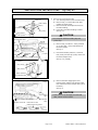
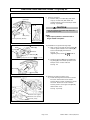
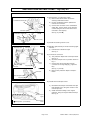
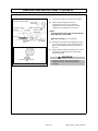
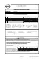
GENUINE PARTS
INSTALLATION INSTRUCTIONS
DESCRIPTION:
APPLICATION:
PART NUMBER:
Fog Lamp Kit
Juke(2011)
Fog Lamp Kit with auto light(B61E0 1KM0A)
Fog Lamp Kit without auto light (B61E0 1KM0B)
KIT CONTENTS:
Item
A
B
C
QTY
2
1/1
2
Description
Application
D
1
Combination Switch
E
1
Installation Instruction Replacement Template
Service Part Number
26150 8990B
26910/5 1KA0A
01115 00271
25560 JV51A
25560 JV12A
---
Fog lamp
Bracket (RH/LH)
Bolt
With auto light
Without auto light
㻾㻴
A
㻸㻴
B
C
D
E
TOOLS REQUIRED:
ł Clip clamp tool
ł Torque wrench
ł Socket wrench (8mm), (10mm)
ł Phillips screwdriver
ł Needle nose pliers
ł Masking tape
ł
PRE-INSTALLATION CAUTIONS/NOTES:
CAUTION
ł 㻯㼍㼞㼑㻌㼙㼡㼟㼠㻌㼎㼑㻌㼠㼍㼗㼑㼚㻌㼚㼛㼠㻌㼠㼛㻌㼟㼏㼞㼍㼠㼏㼔㻌㼛㼞㻌㼐㼍㼙㼍㼓㼑㻌㼍㼚㼥㻌㼏㼛㼙㼜㼛㼚㼑㼚㼠㼟㻌㼐㼡㼞㼕㼚㼓㻌㼠㼔㼑㻌㼞㼑㼙㼛㼢㼍㼘㻌㼛㼞㻌
replacement process.
NOTE:
ł Dealer Installation Recommended. Instructions refer to Service Manual.
ł Use caution when removing trim parts to avoid breaking clips.
1) Apply Parking Brake.
2) Make sure the shift lever is engaged in "P" or "N" position.
Preset
1
2
3
4
3) Record customer Radio Presets.
A
B
4) Use seat and floor protection.
C
5) Open the hood of the vehicle.
6) Disconnect the negative battery terminal to prevent short circuits during installation.
7) This part is to be installed at a vehicle body surface temperature of 65-100°F.
Page 1 of 6
5
6
B61E0 1KM0x II Rev.03/08/2010
INSTALLATION INSTRUCTIONS - Fog Lamp Kit
INSTALLATION PROCEDURE:
Yellow Clip Fig. 1-1
8)
Fillet molding
Clips(2)
Claws
(4 locations)
Clip (reuse)
Removal of front bumper lower
a) Turn steering wheel counter clockwise fully.
b) Remove clip (1 on each side) from fillet
molding of wheel house.
c) Remove 4 claws and 2clips which secure
the fillet molding.
d) Front side of the fillet molding is raised.
See Fig. 1-1.
: Clip position
CAUTION
: Claw position
Fig. 1
Front bumper lower
• Do not peel-off fillet molding beyond
yellow clip.
View a
Bolt
(1:reuse
(behind the
fender protector)
e)
Bolt
(1:reuse)
Clip
(1:reuse)
Clip
(1:reuse)
Bolts
(2:reuse) Clips(3:reuse)
Remove clip (3 locations : reuse) and bolt
(2 on each side : reuse) that attaches in
the front bumper.
See Fig. 1
f)
Bolts (2:reuse)
Peel-off the fender protector, it removes
bolt (reuse) and the clip (reuse) which lock
the front bumper lower.
See Fig. 1-2 (View a).
Fig. 1-2
View a
Clip (reuse)
Bolt (reuse)
Fender protector
Front bumper lower
Fig. 2
g)
Remove the tabs engaging the front
bumper upper and the front bumper lower,
then remove the front bumper lower (at 10
locations ).
See Fig. 2.
CAUTION
Front bumper
upper
: Tab position (10 locations)
Section view of tab
• Take care not to damage the removed
tabs, which will be reused.
Front bumper
lower
Push down the tab
putting hand from behind.
Page 2 of 6
B61E0 1KM0x II Rev.03/08/2010
INSTALLATION INSTRUCTIONS - Fog Lamp Kit
INSTALLATION PROCEDURE:
Fig. 3
9)
Removal of finisher
a) Remove bolt (1 on each side) and metal
clips (2 on each side) that attach the
existing finisher to the front bumper lower.
Metal clips
See Fig. 3 (View b).
View b
CAUTION
View b
• Do not remove the metal clips from the
front bumper lower.
NOTE:
• Clips require patience. Use three inch or
longer needle nose pliers.
Bolt (reuse)
Existing finisher (discard)
Needle nose pliers
Fig. 4-1
Guide
Bolt [C]
Fog lamp [A]
Guide
Rib
10) Installation of right and left fog lamps
a) Align 2 ribs on the side of the fog lamp [A]
with the guide located on the bracket [B].
Secure with bolt [C] from bottom.
See Fig. 4-1
㻔㼀㼕㼓㼔㼠㼑㼚㼕㼚㼓㻌㼠㼛㼞㼝㼡㼑㻌㼛㼒㻌㼎㼛㼘㼠㻌㼇㻯
㻯 㼉㻌㻌㻌㻌㻌㻌㻌㻦㻌㻡㻚㻡㻌㻺㻙㼙㻕
Bracket [B]
Rib
(Tightening torque of Torx wrench
: 5.5 N-m)
b) Install the bracket [B] which installed the
fog lamp [A] in the metal clip of the front
bumper lower. It locks with bolt.
Fig. 4-2
See Fig. 4-2
Bracket [B]
Bolt (reuse)
Fig. 5
Column cover
11) Removal of steering column cover
a) Rotate steering wheel clockwise to access
RH screw. Remove RH screw. Rotate
steering wheel counter clockwise to access
LH screw. Remove LH screw. Remove
steering column cover upper and partially
detach lower cover.
View c
See Fig. 5 (View c).
View c
Column cover (upper)
Column cover (lower)
Screws (reuse)
Page 3 of 6
B61E0 1KM0x II Rev.03/08/2010
INSTALLATION INSTRUCTIONS - Fog Lamp Kit
INSTALLATION PROCEDURE:
Fig. 6
Combination Switch [C]
View d
Connector
12) Replacement of combination switch
a) Remove the Screws which secure the
existing combination switch.
b) Lift the combination switch upward and
remove the connector.
c) Connect the connector to the combination
switch [C]. Secure switch to the steering
column Using the two screws which were
removed in the step 5a).
See Fig. 6 (View d).
Combination Switch [C]
View d
Screws (reuse)
13) Install the steering column cover
Front bumper upper
Taped pre-wire
Connector
Protection tape
View e
Protection
tape
Front bumper
lower
Taped pre-wire
Fog lamp [A]
Connector
Fig. 7
Fog lamp [A]
14) Release right and left pre-wired vehicle fog light
harness.
a) Pull harness to break the tape.
See Fig. 7.
15) Connect the connector
a) The protection tapes stick to bumper-fascia.
See Fig. 7.
b) Set front bumper lower to position shown in
Fig. 7.
c) Connect the vehicle fog lamp harness
connector to the fog 䡈amp [A]. (right and
left)
See Fig. 7 (View e).
d) Remove the protection tapes to bumperfascia.
View e
Connector
Front bumper lower
Fog lamp [A]
Fig. 8
16) Install the front bumper lower.
Reinstall front bumper lower bolts and clips
that labeled reuse, using the reverse of the
removal process.
b) Install the fillet molding to the original
positions. Using the original bolts and clips.
See Fig. 8.
a)
Front bumper
upper
: Tab position (10 locations)
Front bumper
lower
Page 4 of 6
B61E0 1KM0x II Rev.03/08/2010
INSTALLATION INSTRUCTIONS - Fog Lamp Kit
INSTALLATION PROCEDURE:
Fig. 9
h=height of center of lamp body
(Actually measured height)
Lamp (Bulb)
Center line
h
Cut-off line Screen
upper line
Phillips screwdriver
Screen
60mm
Height of center
of lamp body
17) Connect the negative terminal of the battery.
18) Ensure that the fog lamp comes on.
The fog lamp comes on only when the
headlamp is set to the low beam. At other
positions, the fog lamp will not come on.
NOTE:
• The fog lamp will not come on when the fog
lamp SW only is turned ON.
h
䚾optional process䚿 (only if necessary)
3m
Illuminated
light
Flat surface
Fig. 9-1
19) Perform the photometric axis adjustment (see
Fig. 8) by turning the screw located under the
lamp using a Phillips screwdriver as shown in
Fig. 9-1.
20) Ensure that the electric equipment, such as the
small lamp, headlamp and turn signal lamp,
functions properly.
CAUTION
Downward
Upward
• Be sure to check to see if the small lamp,
headlamp and turn signal lamp function
properly.
Page 5 of 6
B61E0 1KM0x II Rev.03/08/2010
INSTALLATION INSTRUCTIONS - Fog Lamp Kit
CHECK AFTER INSTALLATION
1) Please check that the installation has no problem.
䕕 a) Confirm connection of connector is secure.
䕕 b) Confirm whether wire harness is fixed.
䕕 c) Confirm no part moving which will cause rattling noise.
䕕 d) Confirm harness is protected from damage by sharp bracket edges.
FUNCTION CHECK
䕕
䕕
䕕
1) Re-connect battery negative terminal.
2) When auto light is not provided
- With the low beam of the headlamp being illuminated, the fog lamp comes on when
the fog lamp SW.ON is selected.
3) When auto light is provided
- With the lighting switch set to AUTO position and the low beam of the headlamp
being illuminated, the fog lamp comes on when the fog lamp SW.ON is selected.
REINSTALLATION OF REMOVED PARTS
䕕
1) All removed vehicle parts have been reinstalled.
CAUTION
• Use caution when re-installing vehicle parts to avoid damage, scratch, or breaking of
mounting clips.
䕕
2) Clean interior of vehicle.
VEHICLE CHECK
䕕
䕕
䕕
䕕
䕕
䕕
䕕
1)
2)
3)
4)
5)
6)
7)
Remove all tools from the vehicle.
Inspect reinstalled vehicle parts for proper panel fit.
Turn ignition to ON position.
Reset radio presets to the recorded setting.
Confirm proper radio operation.
Initialize sun roof, and power window operation.
Turn ignition to off position.
CAUTION
• During reinstallation, please use caution so as not to cause the stacking or pinching of the
vehicle's harness, or damage any parts.
Page 6 of 6
B61E0 1KM0x II Rev.03/08/2010