1
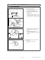
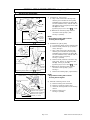
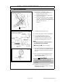
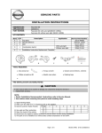
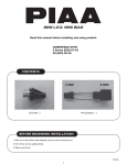
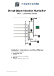
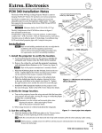
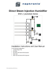
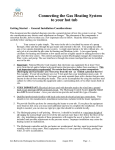
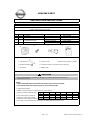
GENUINE PARTS
INSTALLATION INSTRUCTIONS
1.
2.
3.
DESCRIPTION:
APPLICATION:
PART NUMBER:
4.
KIT CONTENTS:
Fog Lamp Kit
Rogue (2011)
B61E0 1VK0A (With auto light)
B61E0 1VK0B (Without auto light)
Description
Fog lamp
Bolt
Application
Item
A
B
QTY
2
2
C
1
Combination Switch
D
1
Installation/handling manual
A
5.
6.
Service Part Number
26150 8990B
--25540 CM31E
25540 EE90E
---
With auto light
Without auto light
B
C
D
TOOLS REQUIRED:
• Clip clamp tool
• Torque wrench
• Socket wrench (8mm), (10mm)
• Phillips screwdriver
• Universal extension of socket wrench (optional)
• Torx driver
• Masking tape
PRE-INSTALLATION CAUTIONS/NOTES:
CAUTION
• Care must be taken not to scratch or damage any components during the removal or
replacement process.
NOTE:
• Dealer Installation Recommended. Instructions refer to Service Manual.
• Use caution when removing trim parts to avoid breaking clips.
1) Apply Parking Brake.
2) Make sure the shift lever is engaged in "P" or "N" position.
4
5
Preset
1
2
3
3) Record customer Radio Presets.
A
B
4) Use seat and floor protection.
C
5) Open the hood of the vehicle.
6) Disconnect the negative battery terminal to prevent short circuits during installation.
7) This part is to be installed at a vehicle body surface temperature of 65-100°F.
Page 1 of 5
6
B61E0-1VK0A~1VK0B II 04/20/10
INSTALLATION INSTRUCTIONS - Fog Lamp Kit
7.
INSTALLATION PROCEDURE:
Fig. 1-1
1)
Removal of existing finisher
a) Remove the mudguard located under the
front bumper. (right and left)
b) Pull down on front fender protector to
gain access to front fender protector.
(right and left)
See Fig. 1-1 , 1-2.
(1) Remove the clips (2 locations : reuse)
(2) Remove the bolts (2 locations : reuse)
(3) Remove the torx (3 locations : reuse)
Front
fender protector
Mudguard
View A
Torx (3 : Reuse)
View A
Fig. 1-2
Clips
(3 : Reuse)
Bolts
(2 : Reuse)
Mudguard
Front
fender protector
Masking tape
Apply masking tape to the bumper around
the existing finisher. (right and left)
See Fig. 2.
d) Push two claws from inside the bumper to
remove the existing finisher.
Claw position: At 12 and 5 o'clock position.
See Fig. 2.
c)
Fig. 2
Claw
View B
Existing finisher
Claw
: Claw position
Taped pre-wire
View B
Fig. 3
2)
Release right and left pre-wired vehicle fog
light harness.
a) Pull harness to break the tape.
See Fig. 3.
Black connector
Page 2 of 5
B61E0-1VK0A~1VK0B II 04/20/10
INSTALLATION INSTRUCTIONS - Fog Lamp Kit
8.
INSTALLATION PROCEDURE:
Fog lamp [A]
Guide
View C
Fig. 4
Rib
Bolt [B]
Guide
3) Installation of left fog lamp
a) Align 2 ribs on the side of the fog lamp
with the groove located on the fog lamp
installation hole. Insert the fog lamp [ A]
into the installation hole, until the claw on
the bottom locks on fog lamp. Secure with
bolt [B] from inside.
(Tightening torque of Torx wrench
: 5.5 Nm)
b) Connect the vehicle fog lamp harness
Rib
View C
Fog lamp [A]
connector to the fog lamp. (left)
Bolt [B]
Vehicle
fog lamp
harness
connector
Bottom locking tab
Tightening torque of Torx wrench
:5.5N-m]
View D
Fig. 5
Bolt [B]
Fog lamp [A]
Fog lamp [A]
Clip
(1 : reuse)
View D
See Fig. 4 (View C).
NOTE:
• Align bottom locking tab to ensure
securing hole is aligned.
4) Installation of right fog lamp
a) Turn steering wheel counter clockwise fully.
b) Remove fender protector clip (1 location :
reuse). See fig.5.
c) Align 2 ribs on the side of the fog lamp
with the groove located on the fog lamp
installation hole. Insert the fog lamp [ A]
into the installation hole, until the claw on
the bottom locks on fog lamp.
See Fig. 5 (View D).
d) Remove fender protector to access to fog
lamp screw, See Fig. 5. and secure with
bolt [B]. See Fig. 5 (View D).
Fender protector
Tightening torque of Torx wrench
(Tightening torque of Torx wrench
Vehicle
fog lamp
harness
connector
:5.5N-m]
Fig. 6
Column cover
View E
Tilt steering
handle
View E
Column cover (upper)
Steering lock escutcheon
: 5.5 N-
Connect the vehicle fog lamp harness
e) m)
connector to the fog lamp. (right)
f)
See Fig. 5.
Remove the masking tape. (right and left)
NOTE:
• Align bottom locking tab to ensure
securing hole is aligned.
5) Removal of steering column cover
a) Remove steering lock escutcheon.
b) Remove 3 screws of column cover.
c) Unlock tilt steering handle to free steering
column.
d) Remove column cover.
See Fig. 6 (View E).
Column cover (lower)
Screws (3 : reuse)
Page 3 of 5
B61E0-1VK0A~1VK0B II 04/20/10
INSTALLATION INSTRUCTIONS - Fog Lamp Kit
9.
INSTALLATION PROCEDURE:
Fig. 7
Combination Switch [C]
6) Replacement of combination switch
a) Remove the two pawl which secure the
existing combination switch.
b) Lift the combination switch upward and
remove the connector.
c) Connect the connector to the combination
switch [C]. Secure switch to the steering
column. Using the two screws which were
removed in the step 5a).
See Fig. 7.
: Pawl position
Fig. 8
h=height of center of lamp body
(Actually measured height) Lamp (Bulb)
Center line
h
Cut-off line
upper line
Screen
Phillips screwdriver
Screen
Height of center
of lamp body
7)
Install the steering column cover.
8)
Connect the negative terminal of the battery.
9)
Ensure that the fog lamp comes on.
The fog lamp comes on only when the
headlamp is set to the low beam. At other
positions, the fog lamp will not come on.
NOTE:
• The fog lamp will not come on when the
fog lamp SW only is turned ON.
60mm
h
3m
Illuminated
light
Flat surface
Fig. 8-1
optional process (only if necessary)
10) Perform the photometric axis adjustment (see
Fig. 8) by turning the screw located under the
lamp using a Phillips screwdriver as shown in
Fig. 8-1.
11) Ensure that the electric equipment, such as
the small lamp, headlamp and turn signal
lamp, functions properly.
Downward
Upward
CAUTION
• Be sure to check to see if the small lamp,
headlamp and turn signal lamp function
properly.
12) Install the Front fender protector and
Mudguard to the original positions. Using the
original bolts and clips.
Page 4 of 5
B61E0-1VK0A~1VK0B II 04/20/10
INSTALLATION INSTRUCTIONS - Fog Lamp Kit
10.
CHECK AFTER INSTALLATION
1) Please check that the installation has no problem.
a) Confirm connection of connector is secure.
b) Confirm whether wire harness is fixed.
c) Confirm no part moving which will cause rattling noise.
d) Confirm harness is protected from damage by sharp bracket edges.
11.
FUNCTION CHECK
1) Re-connect battery negative terminal.
2) When auto light is not provided
- With the low beam of the headlamp being illuminated, the fog lamp comes on when
the fog lamp SW.ON is selected.
3) When auto light is provided
- With the lighting switch set to AUTO position and the low beam of the headlamp
being illuminated, the fog lamp comes on when the fog lamp SW.ON is selected.
12.
REINSTALLATION OF REMOVED PARTS
1) All removed vehicle parts have been reinstalled.
CAUTION
• Use caution when re-installing vehicle parts to avoid damage, scratch, or breaking of
mounting clips.
2) Clean interior of vehicle.
13.
VEHICLE CHECK
1)
2)
3)
4)
5)
6)
7)
Remove all tools from the vehicle.
Inspect reinstalled vehicle parts for proper panel fit.
Turn ignition to ON position.
Reset radio presets to the recorded setting.
Confirm proper radio operation.
Initialize sun roof, and power window operation.
Turn ignition to off position.
CAUTION
• During reinstallation, please use caution so as not to cause the stacking or pinching of the
vehicle's harness, or damage any parts.
Page 5 of 5
B61E0-1VK0A~1VK0B II 04/20/10
GENUINE PARTS
OWNERS MANUAL - Fog Lamp -
Handling instructions
Caution
Advice
Caution
Be sure to
observe the
caution for
safety.
Advice
Tips
Be sure to observe the caution for safety.
Failure to observe the caution may cause damage or accident.
Be sure to observe the advice for your vehicle.
Failure to observe the advice may cause damage to your vehicle or may not
assure the designed performance.
• The illuminating direction of the lamp has been adjusted in such a
direction that it does not dazzle. Do not tamper the illuminating direction
• Never modify the fog lamp
• While the fog lamp is illuminated or immediately after it goes out, the
lamp body and lens are still very hot. Never touch them
• If a bulb other than the designated one is used, it may cause a vehicle
fire. Be sure to use the designated bulb.
• Never modify the harness, bulb, etc.
• Use the fog lamp when visibility turns bad, for example, when it is foggy,
evening, rainy or snowing.
• Remember that the battery may be discharged if you let the lamp remain
illuminated when the engine is not running
• If the bulb will not come on, contact the dealership from which you have
bought the fog lamp.
How to operate the switch
1) When auto light is not provided
- With the low beam of the headlamp being
illuminated, the fog lamp comes on when
the fog lamp SW.ON is selected.
2) When auto light is provided
- With the low beam of the headlamp being
illuminated, the fog lamp comes on when
the fog lamp SW.ON is selected.
- With the lighting switch set to AUTO
position and the low beam of the headlamp
being illuminated, the fog lamp comes on
when the fog lamp SW.ON is selected.
Fog lamp illuminating
position
Fog lamp illuminating
position
Lighting switch
Fog lamp switch
Page 1 of 1
Lighting switch
Fog lamp switch
X0000-XX000II 9/00/08