1
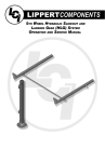
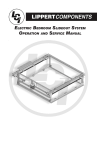
LIPPERTCOMPONENTS, INC.
TOW - N - STOW
OPERATION
AND
SERVICE MANUAL
Table of Contents
Introduction............................................................................................. 1
Safety Information...................................................................................2
Features & Dimensions.......................................................................... 2
Load & Component Specs.................................................................... 5
General Maintenance............................................................................. 6
Towing..................................................................................................... 8
Converting Trailer to Storage Unit......................................................... 9
Converting Storage Unit to Trailer.........................................................14
Removing Tailgate..................................................................................15
Removing Fender Skirt...........................................................................16
Removing Doors.....................................................................................17
Removable Shelves & Hidden Storage Bins.........................................18
Options....................................................................................................19
Replacement Parts..................................................................................19
Warranty..................................................................................................20
TRAILER AXLE MANUAL...................................................................... 21
Introduction
Combining years of experience in the trailer frame and recreational
vehicle industry with the newest and most innovative technology, Lippert
Components, Inc. is proud to announce the addition of the Tow-N-Stow Cargo
Trailer and Storage Unit.
The following publication is designed to give the customer an easy-tounderstand operation and service manual to provide useful and important
information. The quality of the Lippert name and the finest materials utilized in
the production of the Tow-N-Stow provide you lightweight quality cargo towing
combined with the convenience of a storage unit.
Quality comes threefold in Lippert Components, Inc.
- The finest quality materials
- The latest technology and design
- The quality standards maintained from materials to final assembly
All three points provide the customer with the best product they can
possibly buy and the satisfaction of knowing they can trust the equipment on
which they have spent their hard-earned money.
Lippert Components, Inc. thanks you for purchasing the Tow-N-Stow.
When you speak of Lippert Components, Inc., our quality stands beside you.
Safety Information
The “CAUTION” symbol will be seen throughout this manual and is a
sign that a service or maintenance procedure has a safety risk involved and
may cause serious injury or death if not performed safely and within the
parameters set forth in this manual.
Always wear eye protection when performing service or maintenance to
the vehicle. Other safety equipment to consider would be hearing protection,
gloves and possibly a full face shield, depending on the nature of the service.
This manual provides general service and maintenance procedures.
Many variables can change the circumstances of the service procedure, i.e.,
the degree of difficulty involved in the service operation and the ability level of
the individual performing the operation. This manual cannot begin to plot out
procedures for every possibility, but will provide the general instructions for
effectively servicing the vehicle. In the event the skill level required or the
procedure too difficult, a certified technician should be consulted before
performing the necessary service. Failure to properly service the vehicle may
result in voiding the warranty, inflicting injury or even death.
Features Diagram
2
• Tow with virtually any vehicle. All you need is a Class 1 trailer hitch.
• Perfect for landscaping, building materials, camping/recreation and more.
• Easy to hitch. Easy to load. Easy to clean.
• Key-locking doors and tailgate.
R
• Multiple options for THULE cargo tie downs and security.
• Ideal for residential areas where a traditional trailer isn’t practical.
• Converts to storage unit in less than one minute.
CAUTION:
The Tow-N-Stow should always be converted from trailer to storage unit
and back to trailer with two adults.
• Tilt upright, retract axle assembly and fold in the tow bar. Done.
• Perfect for yards or garages.
• Optional shelving system allows for multiple storage choices and variations.
3
Dimensions Diagram
4
LOAD SPECIFICATIONS
• Internal Cubic Cargo Capacity - Approximately 46 cu. ft. (1303 liters)
• Unit Weight: Approximately 400 lb. (181 kilograms)
• GVWR: 1490 lb. (676 kilograms)
• Payload Max: 1000 lb.
• Wheels, steel, 8” 4 bolt 4.80-8, 760 lb. max load range C tire
• Overall length with Tow Bar: 103” (330 centimeters)
COMPONENT SPECIFICATIONS
• No wheel wells in cargo area provides room for a 4’ x 8’ sheet of building
materials. Also allows for easy loading and hauling of lawn mowers, four
wheelers, etc.
• Integrated side wall brackets allow adjustable multiple storage shelving
positions.
• Integrated brackets also allow cargo separators in vertical or horizontal
positions - even a table top position.
• Internal storage compartments for straps and cinches.
• Removable tailgate requires no tools.
• Doors are removable requiring no tools or can be latched open while hauling.
• Watertight in both modes.
TRAILER MODE
• Easily removable fully opening doors
• Mounts for automotive roof racks
• Key locking gate latch
• Removable tailgate allows use of ramps
• THULE cargo tie down rings
• Tow bar release mechanism
• Deck width full 48-1/2"
• LED rear and side marker lamps
• Steel reinforced high impact polymer body
• Independent torsion axle suspension
• Grab handles and tie off rails
STORAGE MODE
• Locking axle and tow bar
• Lowered axle keeps weight at base for increased stability in storage
mode
• Integrated shelf and cargo separator brackets
• Grab handles and tie off rails
• Key locking latch
• Internal storage bins
• Optional plastic shelving
R
5
GENERAL MAINTENANCE
LIGHTING CONNECTOR
Trailer lights must work properly both for your
safety and to comply with the law. A thin layer
of dielectric grease on the connector can prevent
corrosion from building up. If corrosion is present,
a scraping tool or wire brush can clean the
connectors. Be sure to unplug the connector
carefully and always unplug when cleaning the
connector and applying grease.
CAUTION:
Unplugging the wire connector prevents the system from shorting out during the
cleaning and greasing process.
Check all lights to be sure wiring is in place and there is no visible damage.
Repair any damage prior to using the trailer.
NUTS & BOLTS: Periodically check for proper torque specs with a calibrated
torque wrench.
Torque WHEEL NUTS to 65 ft. lb.
GREASE REQUIRED: Keep the tongue pin and both wheel pins lightly greased
or use a silicone-based lubricant. Keep the Wheel Blocks/Swingarm and
Tongue/Frame mating surfaces lubricated. Keep the hitch ball greased.
TIRES: Keep your tires inflated to manufacturer’s specs (see tire sidewall
ratings). Check both tires at each gas stop, or break. Check with a quality tire
gauge. Tire failure can be caused by overloading the trailer beyond it’s towing
capacity and under inflated tires. Both issues will cause undo pressure on the
sidewalls of the tires and cause the tire to fail and are not subject to warranty
coverage.
WHEEL BEARINGS: The wheel bearings are Super Lube and must be serviced
on the schedule found in the Lippert Components, Inc. Trailer Axle Manual.
6
VEHICLE HITCH AND BALL MOUNT
The hitch is installed on the tow vehicle. The ball mount inserts into the hitch
receiver and is secured with an “L” pin and hair pin. The ball is secured to the
ball mount with a locking washer and hex nut. Ball mounts are available in
various vertical heights. Choose a ball mount and ball combination that allows
the Tow-N-Stow to travel level and parallel to the ground.
The Tow-N-Stow trailers work with Class I, II, or III hitches with a 2" ball. The
Class I vehicle hitch carries the lightest rating with a maximum 200 lb. tongue
weight and 1500 lb. towing weight and features a 1 1/4" square receiver. A
Class I hitch is more than capable of handling the Tow-N-Stow with ease.
NOTE: If towing with a 4-cylinder vehicle, it is advisable to turn the overdrive
off as it will reduce the strain on the transmission.
TRAILER COUPLER AND BALL
The trailer’s coupler features a ball clamp underneath the latch which tightens
onto the ball when the latch is closed. The coupler latch mechanism must be
securely locked with your safety pin/padlock inserted. The ball should be lightly
greased.
SAFETY CABLE:
Safety cable must be securely attached to the vehicle hitch while transporting
Tow-N-Stow.
CAUTION:
The proper distance from the ground to the top of the hitch ball is 13 1/2
inches for your Tow-N-Stow trailer. Make sure your hitch has provisions
for the connection of your safety cable.
7
TOWING
1. Maintenance schedule should be current.
2. Be sure the hitch, ball mount and 2" ball are all mounted securely to the
tow vehicle.
3. Inspect hitch for corrosion, lubrication and wear.
4. Be sure the trailer coupler is locked on to the hitch ball and safety pin
installed.
5. Inspect safety cables for damage and wear. Engage chains securely.
6. Load trailer with 10% of total weight on the hitch end of trailer. Smaller
trailers front end load should be increased to 15%. Be sure load is balanced
left to right.
7. With heavier loads, make sure the heaviest portion of the load is centered
over the axles. This prevents excessive tongue weight and provides a
smoother balanced tow.
CAUTION:
Do Not Overload! For optimum performance of your Tow-N-Stow, never
exceed 1000 lb maximum payload capacity. Verify that all straps and
clamps are tight and the load secure.
8. Check tire pressure – Tires should be inflated to manufacturer’s specs (see
tire sidewall ratings). Inspect tires for any damage or wear.
9. Check all trailer lights. Do not tow trailer without all lights in working order.
10. Inspect lug nuts/bolts. All should be torqued to spec. See Lippert
Components, Inc. Trailer Axle Manual.
11. Check torque of hanger bolt on suspension.
12. Check that your trailer is towing level. Adjust hitch height if necessary to
level trailer.
CAUTION:
Never step on a trailer that is not hitched to a tow vehicle.
Never ride or allow a passenger in the trailer.
8
CONVERTING FROM TRAILER TO STORAGE
CAUTION:
Never attempt to convert unit from one position to the other position with
small children or animals present. Make sure conversion area is free from
tripping hazards, wet or slippery or uneven ground. Both operators
should wear shoes or boots, sandals or bare feet are not recommended
during conversion.
It is MANDATORY that two adults who are able and suitable to lift and
lower the total weight exceeding 120 lbs before attempting conversion.
CAUTION:
During lowering sequence, weight increases until trailer tires touch the
ground, be prepared to handle in excess of 120 lbs at final angle closest
to ground.
CAUTION:
During storage outside or inside, always store unit with back side placed
near or close against a wall or suitable structure. NEVER leave storage
unit free standing in open yard or driveway area. Wind or persons
pushing on unit can cause unit to fall over backward causing potential
damage to unit or property, injury or death. Always store unit with tow
bar and axle folded into storage positions.
NOTE: It is advisable to prepare an area that is level and firm such as a patio,
concrete or brick or decking for unit to be stored on if outside. A ground pad
extending out from a suitable structure such as a garage, back of the house or
a shed makes a perfect place to store the unit. An 8 ft x 8 ft area or pad is
sufficient. This pad will provide a stable area that can provide a good
foundation for resting unit upon during storage and to provide easy sliding
during conversion.
9
CONVERTING FROM TRAILER TO STORAGE
CAUTION:
Never unhitch the Tow-N-Stow from your vehicle while parked on a hill.
Before unhitching the trailer, block the wheels to avoid trailer or property
damage, injury or death from a runaway trailer.
SAFETY TIP:
It is always safest tounload all contents of the trailer including shelves
and doors prior to conversion.
Disengage the light harness and
the safety cables from the tow
vehicle.
Lift the trailer by the tow bar and
pull the the “T”-handle straight up
to disengage the Lift Handle/Kick
Stand.
Unlatch the coupler from the ball.
Swing the Lift Handle/Kick Stand
forward 90 degrees. Be sure
“T”-Handle pin locks into place.
CONVERTING FROM TRAILER TO STORAGE
Roll trailer to storage area. Area must
be clear of debris and obstruction on
the ground and overhead. Ground
location must be level to prevent
sliding out of place or tipping over
once in storage position.
“T”-handle detail
Using 2 people, lift Tow-N-Stow by
the bottom of the roof or grab bar
until rear edge touches the ground.
Disengage “T”-handle pin and drop
tow bar to the angled conversion
position.
With two persons, place hands on
the handle, and with each person on
opposite sides of the tow bar, lift the
unit in one continuous motion. When
unit is nearly vertical. Continue
holding the handle pulling
“backwards” while the unit continues
rearward until it comes to rest.
CAUTION:
It is advisable to begin lift using a crouch position with bent legs with the
back upright, use legs and arms to lift and not the back to reduce
possible lifting injury. DO NOT LIFT USING A BENDED BACK!
CONVERTING FROM TRAILER TO STORAGE
While holding handles, grasp
“T”-Handles on both sides of the
axle and disengage pins outward.
Swing axle 180o to the fully stowed
position. Be sure “T”-Handle pin snaps
into locked position.
Axle fully stowed and secured.
CAUTION:
Do not store the trailer in any upright position with the tow bar in the
upright position. This condition will make the Tow-N-Stow top heavy and
can tip over causing damage and serious injury or death.
CONVERTING FROM TRAILER TO STORAGE
With one hand, hold the tow bar weight and grasp “T”Handle on the tow bar swing bracket with the other
hand and disengage the pin. See inset.
When the tow bar is disengaged, swing the tow bar
flush to the floor of the Tow-N-Stow. Engage the “T”Handle pin to secure the tow bar. Be sure pin snaps
into the fully seated position.
CONVERTING FROM STORAGE MODE TO TRAILER
CAUTION:
Never attempt to convert unit from one position to the other position with
small children or animals present. Make sure conversion area is free from
tripping hazards, wet or slippery or uneven ground. Remember, both
operators should wear shoes or boots. Sandals and bare feet are not
recommended during conversion.
Slide unit away from wall or structure
and unlock tow bar and lift into
angled conversion position.
While holding handles, grasp
“T”-Handles on both sides of the axle
and disengage pins outward. Swing
axle upward 180o to the fully deployed position. Be sure “T”-Handle
pin snaps into locked position.
With 2 people, grab tow bar
handle and pull backward slightly
until equilibrium is experienced
(no forces) the unit will be at a
slight angle with the front glide
pucks off the ground. Continue
slowly backward and then slightly lift
tow bar arm a few inches until the travel of lock pin in the slot stops. The
weight of the unit should now begin to transfer to the tow arm lift handles.
Slowly walk backward with both persons continuing to hold separate ends of
the lift handle with both hands.
OPTION B: One person, preferrably the taller of the two can work on the
tow bar handle and the other on the opposite side grab bar.
14
CONVERTING FROM STORAGE MODE TO TRAILER
NOTE: As unit travels to its lowest point, more weight is applied onto the tow
bar handles. Once handles are about at waist level, most of the weight is
between there and the ground. Continue to lower handle to ground using arms
and legs with back upright.
While one person holds the unit in
the angled position, the other person
can now unlock the tow bar from the
angled conversion position and lift
tow bar into the towing position.
The spring lock will automatically
lock the arm in place. The lift handle
can now be deployed as a stand or
folded 180o into the trailering
position. This angled position may
also be used to clean out any dirt or
debris from hauling.
REMOVING THE TAILGATE
With one person on either end
holding the tailgate, one person
reaches into the tailgate relase latch
and squeezes the pins together.
The tailgate can then be removed,
using both people, one on each end.
15
REMOVING FENDER SKIRT TO EXPOSE TIRE AND WHEEL
Grasp bottom edge of the Fender
Door and pull straight out.
Next, pull down on Fender Door to
disengage door from fender.
Tire pressure can now easily be checked and the tire/
wheel assembly can be removed.
Prior to replacing the Fender Door
the Snap Clips must be open.
See above.
16
Once the Fender Door is replaced,
engage the Snap Clips as shown in
the photo above.
REMOVING DOORS
The Tow-N-Stow Doors are easily
removed for loads that are taller
than it’s side walls.
Push the Hinge Pin towards the
base of the Tow-N-Stow. This
disengages Hinge Pin from hinge.
Lift the door from the top hinge.
Pull the door from the bottom
hinge and remove the door.
17
REMOVABLE SHELVES AND HIDDEN STORAGE BINS
The Tow-N-Stow comes with 3
removable shelves that can easily
be moved to accommodate a
variety of heights and locations.
With the middle shelf low enough or
removed, side storage bins are
available to stow tie-downs, rope, etc.
TIE DOWN BRACKETS
The Tow-N-Stow is equipped with several tie-down
areas and brackets. The above THULE bracket is
mounted to the floor on the inside of the Tow-N-Stow
to conveniently secure any load.
R
18
OPTIONS
204485 207630 -
Single Shelf
3-Pack of Shelves
REPLACEMENT PARTS
204414
204476
204483
204418
204459
212561
212560
204499
205186
204484
204490
204488
206971
204491
212564
212562
212563
204489
206972
204493
204496
210875
181598
204422
204504
211949
206192
204481
204410
204480
204432
204482
204409
204454
213836
211954
204419
204420
204421
TAILGATE PANEL
TAILGATE LATCH ASSY.
TAILGATE - HORSESHOE ASSY
ROUND FOOT
LICENSE PLATE LIGHT
RUBBER TAILLIGHT GROMMET
TAILLIGHT
TAILGATE RELEASE
TAILGATE LATCH LINKAGE
ROOF ASSEMBLY
SIDE PANEL ASSY - CURBSIDE
FENDER SKIRT - CURBSIDE
GRAB BAR - CURBSIDE
SIDE PANEL ASSY - ROADSIDE
RUNNING LIGHT GROMMET
AMBER RUNNING LIGHT
RED RUNNING LIGHT
FENDER SKIRT - ROADSIDE
GRAB BAR - ROADSIDE
LAMINATED FLOOR
TONGUE ASSY
VINYL HAND GRIP
COUPLER
TONGUE BAR
KICK STAND
SAFETY CABLE
TORSION AXLE
LEFT DOOR ASSY
PANEL ONLY
GRAB BAR ASSY - DOOR
“T”-DOOR HANDLE, NON-LOCKING
RIGHT DOOR ASSY
PANEL ONLY
“T”-DOOR HANDLE, LOCKING
DOOR RELEASE ROD ASSY
LOOP CLAMP
INSIDE CARGO PANEL - RIGHT
INSIDE CARGO PANEL - LEFT
STORAGE COMPARTMENT DOOR
204471
TIE DOWN D-RING
19
WARRANTY
The Tow-N-Stow has been manufactured, tested and inspected in accordance
with carefully specified engineering requirements and is warranted to the original
owner to be free from defects in material and workmanship for the period of one
(1) year, except as herein limited, from date of purchase. The obligation of this
warranty shall be limited to repairing or replacing any part or parts which, in the
opinion of the Company, shall be proved defective in materials or workmanship
under normal use and service during the one-year-period commencing with the
date of purchase. Electrical wiring, paint and coupler are warranted for a period
of (90) days from date of purchase. This warranty does not cover any part or
parts which have been damaged as a result of an accident, misuse, abuse or
which have been modified, altered or repaired. This warranty shall not apply if
the trailer has been subjected to loads in excess of its rated capacity.
Specifications:
Gross Weight:
Carrying Capacity:
Length w/Tow Bar:
Height Shed Mode:
Width:
Depth:
20
500 lb.
1000 lb.
120”
82.5”
69.5”
33.5”
LIPPERTCOMPONENTS, INC.
TRAILER AXLE OPERATION
AND
SERVICE MANUAL
THIS MANUAL COVERS ELECTRIC BRAKE SYSTEMS ONLY
-
SPRING AXLE MODELS NOS.
LCI28 = 2800 lb. Weight Rating
LCI35 = 3500 lb. Weight Rating
LCI52 = 5200 lb. Weight Rating
LCI60 = 6000 lb. Weight Rating
LCI70 = 7000 lb. Weight Rating
SPRING DROP AXLE MODELS
TORSION MODELS NOS.
NOS.
- LCI28-T = 2800 lb. Weight Rating
- LCI28-D = 2800 lb. Weight Rating
- LCI35-T = 3500 lb. Weight Rating
- LCI35-D = 3500 lb. Weight Rating
- LCI52-T = 5200 lb. Weight Rating
- LCI52-D = 5200 lb. Weight Rating
- LCI60-T = 6000 lb. Weight Rating
- LCI60-D = 6000 lb. Weight Rating
- LCI70-T = 7000 lb. Weight Rating
- LCI70-D
Weight
Rating
NOTE:= 7000
Modelslb.
can
be de-rated
per manufacturer’s preference or specifications.
INTRODUCTION
Combining years of experience in the trailer frame and recreational vehicle industry with the newest and most innovative technology,
Lippert Components, Inc. introduces it’s newest addition, The Axle and Running Gear Division. The following publication is designed to give
the customer an easy-to-understand operation and service manual to provide useful and important information. The quality of the Lippert
name and the finest materials utilized in the production of the Axles and Running Gear provide you with hubs, brakes, drums and spindles
that make trailering and braking the finest in the industry.
Quality comes threefold in Lippert Components, Inc.
• The finest quality materials.
• The latest technology and design.
• The quality standards maintained from materials to final assembly.
All three points provide the customer with the best product they can possibly buy and the satisfaction of knowing they can trust the
equipment on which they have spent their hard-earned money. Lippert Components, Inc. thanks you for purchasing our Axles and Running
Gear. When you speak of Lippert Components, Inc., our quality stands beside you.
WARNING!
SAFETY INFORMATION
The “WARNING!” symbol above is a sign that a service or maintenance procedure has a safety risk involved and may cause serious injury
or death if not performed safely and within the parameters set forth in this manual. Always wear eye protection when performing service or
maintenance to the vehicle. Other safety equipment to consider would be hearing protection, gloves and possibly a full face shield,
depending on the nature of the service.
This manual provides general service and maintenance procedures. Many variables can change the circumstances of the service
procedure, i.e., the degree of difficulty involved in the service operation and the ability level of the individual performing the operation. This
manual cannot begin to plot out procedures for every possibility, but will provide the general instructions for effectively servicing the
vehicle. In the event the skill level required or the procedure to difficult, a certified technician should be consulted before performing the
necessary service. Failure to correctly service the vehicle may result in voiding the warranty, inflicting injury or even death. The owner’s
manual for your unit may have more procedures for service and maintenance.
HUBS/DRUMS/BEARINGS
Hub Removal
To remove the hub assembly for inspection, maintenance or service, follow the six (6) steps below:
WARNING!
Lift unit by the frame and never the axle or suspension. Do not go under the unit unless it is properly supported by jack stands.
Unsupported units can fall causing serious injury or death.
1. Lift trailer and support it per manufacturer’s requirements.
2. Remove the wheel.
3. Remove the grease cap by prying the edge out of the hub.
4. Pull the cotter pin from the castle nut or, if the hub is equipped with the Super Lube system, bend the locking tang down and remove the
outer spindle nut.
5. Remove the spindle washer.
6. Pull the hub off the spindle. Do not let the outer bearing cone fall free of the assembly. The inner bearing cone will be contained by the
seal and will not fall out.
NOTE: A gear puller may be necessary to remove hub from spindle.
Brake Drum Inspection
The brake shoes contact the drum surface and the magnet contacts the armature. These surfaces are subject to wear and should be
inspected periodically. The drum surface should be remachined if scored more than .020” or out of round by more than .015”. The drum
should be replaced if scoring or wear is greater than .090”. The inner surface of the brake drum that contacts the brake magnet is the
armature surface. If the armature surface is scored or worn unevenly, it should not be machined any more than .030". The magnets should
be replaced whenever the armature surface is refaced and vice versa.
Drum
Diameter
10”
10.090”
12”
12.090”
NOTE: Make certain that the wheel bearing cavities are clean and free of contamination before reinstalling bearing and seals.
Resurfacing procedures can produce metal chips and dust that can contaminate the wheel bearings and cause failure.
Bearing Inspection
Wash all grease and oil from the bearing cone using a suitable solvent. Dry the bearing with a clean, lint-free cloth and inspect each roller
completely. If any pitting, spalling, or corrosion is present, then the bearing must be replaced. The bearing cup inside the hub must be
inspected.
NOTE: Bearings must always be replaced in sets of one cone and one cup.
W ARNING!
Always wear eye protection when servicing the axle, brakes, hubs, springs and wheels.
Failure to wear eye protection may result in serious injury.
Bearing Lubrication - Grease
Bearing grease should be replaced every 12,000 miles or 12 months, whichever comes first. Remove all old grease from wheel hub and
bearings first. Bearings should be packed by machine if possible. Packing bearings by machine is preferable; however, packing by hand is
a viable alternative.
Follow these procedures to repack bearings by hand:
1. Place grease into the palm of your hand.
2. Press widest end of bearing into the outer edge of the grease, forcing grease into the inner area of the bearing between the two
adjacent rollers.
3. Repeat this process while turning bearing from roller to roller until all rollers are coated.
4. Apply a light coat of grease into the bearing cup surface.
5. Reassemble bearing into cup.
RECOMMENDED WHEEL BEARING LUBRICATION SPECIFICATIONS
Grease:
Thickener Type ........................................................................ Lithium Complex
Dropping Point ............................................................. 230°C (446°F) minimum
Consistency ..................................................................................... NLGI No. 2
Additives .....................................................EP, Corrosion & Oxidation Inhibitors
Base Oil .............................................................. Solvent Refined Petroleum Oil
Base Oil Viscosity ....................................@40°C (104°F) 150cSt(695 SUS) Min.
Viscosity Index ............................................................................... 80 Minimum
Pour Point ....................................................................... -10°C (14°F) Minimum
Approved Sources:
Mobil Oil ................................................................................... Mobilgrease HP
Exxon/Standard ................................................................................. Ronex MP
Kendall Refining Co. ..................................................................... Kendall L-427
Ashland Oil Co. ..................................................... Valvoline Val-plex EP Grease
Pennzoil Prod. Co. ................................... Premium Wheel Bearing Grease 707L
Seal Inspection and Replacement
Always check the seal to make sure that it is not damaged, nicked, cracked or torn and is in good working order. If there is any
question of condition, replace the seal. Use only the seals specified in the Seal Replacement Chart in the Trailer Axle Manual
found on the LCI website - www.lci1.com
Forward Facing Direction
Procedure to replace seal:
1. Pull seal from the hub with a seal puller. Never push the seal out with the bearing. The bearing may get damaged.
2. Apply a PERMATEX sealant to the outside of the new seal.
3. Tap the new seal into place using a clean, hard wood block.
Bearing Adjustment/Hub Replacement
For adjusting bearings or replacement of removed hub, follow procedures below:
1. Place hub, bearing, washers and castle nut back on axle spindle in the reverse order from which they were removed. Castle nut
should be torqued to 50 ft.-lb. Hub will rotate during this process.
2. Loosen castle nut to back off the torque.
3. Tighten castle nut finger tight until snug.
4. Insert cotter pin (or locking tang if equipped with Super Lube). If cotter pin or tang does not line up with hole, back castle nut up
slightly until pin or tang can be inserted.
5. Bend cotter pin over to lock nut in place (or locking tang in the case of Super Lube). Nut should be free to move with only the
cotter pin keeping it in place.
ELECTRIC BRAKES
THIS MANUAL COVERS ELECTRIC BRAKE SYSTEMS ONLY
The basic structure of the Electric Brakes on your trailer will resemble the brakes on your car or tow vehicle, with one major difference;
your trailer implements an Electric Actuation system and your tow vehicle utilizes a hydraulic system. The Electric Braking System
operates in the following order of steps; refer to the Electric Braking System diagram and the brake diagram to follow along:
1. Electric current is supplied to the trailer’s braking system when the tow vehicle’s brakes are applied.
2. From the tow vehicle’s battery, the electricity flows to the brake’s electromagnet.
3. When energized the electromagnets are attracted to the rotating surface of the drums.
4. This moves the actuating levers in the direction the drums are turning.
5. The actuating cam at the end of the shoe forces the primary shoe out to the drum surface.
6. The force of the primary shoe actuates the secondary shoe to contact the drum.
7. The force applied to the brake drum can be increased by elevating the current flow to the electromagnet.
8. Brake nuts to secure the backing plate to the flange should be torqued at 30-50 lbs.
Retracting Spring
Primary Shoe
Secondary Shoe
Actuating Lever
Electro-Magnet
Shoe Hold Down
Adjusting Spring
Adjuster
How to Use Your Electric Brakes Properly
The Lippert Components, Inc. Electric Braking System is synchronized with your tow vehicle brakes.
WARNING!
Never attempt to stop the combined load of the tow vehicle and the trailer by using either the tow vehicle brakes or the trailer brakes only. They
are designed to work together.
You may have to manually make small adjustments occasionally to accommodate changing loads and driving conditions. Synchronization
of tow vehicle to trailer braking can only be accomplished by road testing. Locking up, excessive grab, or delayed application is quite often
due to the lack of synchronization between the tow vehicle and the trailer being towed. High voltage (2V+), Low voltage (2V-) or improperly
adjusted brakes are the most common cause of these problems and can be easily remedied. Prior to any adjustments, your trailer brakes
should be burnished-in by applying the brakes 20-30 times with a 20 m.p.h. decrease in speed, e.g. 40 m.p.h. to 20 m.p.h. Allow ample time
for brakes to cool between application. This allows the brake shoes and magnets to begin seating to the brake drum.
TRAILER WIRE GAUGE CHART
Number of Brakes
Hitch-to-Axle Distance In Feet
2
-
4
Under 30
4
30-50
6
Under 30
6
30-50
Minimum Hookup Wire Gauge
12 AWG
12 AWG
10 AWG
10 AWG
8 AWG
GENERAL MAINTENANCE - ELECTRIC BRAKES
Brake Adjustment
W ARNING!
Prior to testing or adjusting brakes, be sure area is clear of any pedestrians and vehicles. Failure to perform test in a clear area may
result in serious injury or death.
Lippert Components, Inc. Electric Brakes are manually adjustable only. If manual adjusting is needed, the following 6-step procedure can
be utilized. Initially, brakes should be adjusted after the first 200 miles of operation when the brake shoes and drums have “seated.” Next,
check and adjust brakes at 3,000 mile intervals or sooner if they are not performing as intended. The brakes should be adjusted in the
following manner:
1. Jack up trailer and secure on adequate capacity jack stands. Follow trailer manufacturer’s recommendations for lifting and supporting the
unit. Make sure the wheel and drum rotates freely.
W ARNING!
Lift unit by the frame and never the axle or suspension. Do not go under unit unless it is properly supported by jack stands. Unsupported units
can fall causing serious injury or death.
1. Remove the adjusting hole cover from the adjusting slot on the bottom of the brake backing plate.
2. With a screwdriver or standard adjusting tool, rotate the starwheel of the adjuster assembly to expand the brake shoes. Adjust the brake shoes
out until the pressure of the linings against the drum makes the wheel very difficult to turn.
3. Then rotate the starwheel in the opposite direction until the wheel turns freely with a slight lining drag.
4. Replace the adjusting hole cover and lower the wheel to the ground.
5. Repeat the above procedure on all brakes. For best results, the brakes should all be set at the same clearance.
Clean and Inspect Brakes
In the event the braking system encounters symptoms of improper application or failure, immediate inspection and service must be
implemented. During normal use, servicing the braking system once a year is considered normal. Increased usage will require service on a
regulated schedule based on 3000-6000 mile increments. As magnets and shoes become worn, they need to be changed to maintain
maximum braking capability.
Be sure, when disassembling brakes for cleaning, to clean the backing plate, magnet arm, magnet and
shoes. Also, make sure that any and all parts removed for cleaning are placed back into the same brake drum assembly. This is also an
excellent time to check for parts that have become loose or worn.
W ARNING!
POTENTIAL ASBESTOS DUST HAZARD!
Older brake linings have the potential to contain asbestos dust, which has been linked to serious or fatal illnesses. Certain precautions
need to be taken when servicing brakes:
1. Avoid creating and/or breathing any brake dust.
2. Do not machine, file or grind the brake linings.
3. Remove with a damp brush or cloth. Dry brushing or compressed air will cause dust particles to be airborne.
Lubricate Brakes
Prior to reassembling the brake drum assembly, remember to apply a light film of white grease or an anti-seize compound on the brake
anchor pin, the actuating arm bushing and pin, and the areas on the backing plate that are in contact with the brake shoes and magnet
lever arm. In addition apply a light film of grease on the actuating block mounted on the actuating arm.
Magnets
This electric braking system utilizes an electromagnet to actuate the brake shoes. These high-quality magnets provide superior force and
friction to safely and effectively stop the trailer. These magnets should be inspected and serviced on the same schedule as the rest of the
axle system, at east once a year for normal use and more often if the trailer is used extensively. Abnormal or uneven wear is a sign that
the magnet needs to be replaced. Check the surface of the magnet with a straight edge to check for uneven wear. The surface of the
magnet should be completely flat. If the magnet’s coil is exposed in any way, even if normal wear is evident, the magnets should be
replaced immediately. If the electromagnets are replaced, the drum armature surface should also be refaced. If a magnet is replaced on
one side of an axle, it is recommended that the magnet on the opposite brake assembly also be replaced to ensure even braking capacity.
Shoes and Linings
Linings should be replaced if the material is worn to 1/16” or less. Shoes should also be replaced if they become contaminated with grease
or oil or have become scored, pitted or gouged. Heat cracks are normal and rarely require attention. When replacing shoes, both shoes on
the same brake and the brakes on the same axle should all be replaced at the same time, once again ensuring even braking capacity.
Brake linings should be replaced with the similar lining material or obtained directly from LCI. Brake lining data can be found on the surface
of the brake lining. This information can be used to find correct replacement brake lining material. After replacing shoes and linings, your
trailer brakes should be burnished-in by applying the brakes 20-30 times with a 20 m.p.h. decrease in speed, e.g. 40 m.p.h. to 20 m.p.h.
Allow ample time for brakes to cool between application. This allows the brake shoes and magnets to begin seating to the brake drum.
Axle & Suspension Installation
The single most important portion of axle installation is parallel alignment of the trailer axle(s) to the tow vehicle or drive axle(s). Parallel
installation allows for correct and safe control, prolonged tread life and will all but eliminate dog-tracking. Proper alignment is most readily
achieved by measuring from the center of the trailer king pin to the center of each end of the axles. The tolerance should not vary any
more than 1/16". The difference between the centers of one axle and end centers of the other axle must not vary more than 1/8" in multiple
axle configurations. Lippert Components, Inc. tubular axles are made of high strength steel to prevent metal fatigue and provide the best
possible welding conditions. The round tubular axles allow for even and uniform structure.
Directions:
1. Position Brake Axles (if used) so that lead wires are on the roadside of the trailer.
2. For Leaf Spring axles, use all AP Kits provided with axle to install as shown in Fig.1 below and torque fasteners as specified in the
chart below.
Shackle Link
Center Hanger
U-Bolt
Rear Hanger
Front
Hanger
Tie Plate
Fig. 1
Shackle Bolts
Equalizer
Sprung Axle Torque Specifications
Axle Size
U-Bolts
Shackle Bolts
Minimum ft.-lb.
Maximum ft.-lb.
55
30
70
50
3. For Torsion installation, mount axle bracket to frame bracket (shown in Fig. 2 below) and torque fasteners as specified in the
chart below.
Fig. 2
Outside bracket dimension
Outside frame
Washer(s) must be placed against the slotted
hole in the axle bracket
Torsion Torque Specifications
Axle Size
Bolt Size
Torque ft.-lb.
#8-#9
1/2
70-90
#10-#13
5/8
120-155
NOTE: Low profile brackets have plain round
holes
W ARNING!
Always wear eye protection when servicing the axle, brakes, hubs, springs and wheels. Failure to wear eye protection may result in serious injury.
Suspension Systems
The suspension systems incorporated into Lippert Component, Inc. axles are designed to provide the following benefits:
1. Attach the axle to the trailer.
2. Dampen the effects of road shock.
3. Provide stability to the trailer.
All Lippert suspension systems are available in single and multiple axle configurations. For specific or custom applications, please contact
Lippert Components, Inc. Axle Division.
Double-Eye Leaf Springs
Double-eye leaf springs have eyes at either end of the spring assembly with nylon bushings to assist in preventing wear. U-bolts hold the
springs to the axle with a plate. The articulation of this suspension occurs when the eyes rotate on the wear surfaces provided in eyes of
the springs and on the equalizers. This suspension is also available in single and multiple axle configurations. In trailers with 2 or more
axles, the additional movement is maintained by an equalizer. This feature allows for even load handling from axle to axle.
Torsion Suspension System
1. The Lippert Components, Inc. Torsion Suspension system is designed to offer superior qualities over leaf spring technology. The Lippert
Components, Inc. Torsion Suspension system is bracketed to the trailer’s frame and housed inside the trailer axle’s tube.
2. The spindle is connected to a swing arm, the swing arm is connected to a square inner bar that is sheathed in rubber and as the swing
arm rotates and experiences the torque and resistance of driving conditions, the characteristics of the rubber absorb and distribute
Inspection
the load providing benefit over leaf spring suspensions.
All the components of your suspension system should be visually inspected for signs of wear, damage or loose fasteners at least every
6,000 miles. When replacing or tightening loose fasteners, consult the torque charts on pages 3 & 4 for correct torque values. Worn
spring
bushings
or sagging
orTorsion
broken Suspension
springs should
be replaced
3. Theeye
Lippert
Components,
Inc.
system
requiresusing
very the
littlefollowing
attentionmethod:
in regards to maintenance. Normal inspection of
1.
the trailer
with the wheels
just offAxle
the ground.
Follow
the manufacturer’s
recommendations
for lifting
and supporting
the unit.for
theSupport
entire Lippert
Components,
Inc. Trailer
system can
be applied
to the Torsion
Suspension system.
See inspection
procedures
2.
After the
unit is properly
system
components
in this supported
manual. place a suitable block under the axle tube near the end to be repaired. This block is to support the
weight of the axle only so that SUSPENSION COMPONENTS can be serviced or replaced.
3. Disassemble the U-bolts, nuts, and tie plates.
4. Remove the spring eye bolts and the spring.
5. If the spring eye bushings are to be replaced, press out the old bushing by hand or tapping out with a punch.
6. Free-floating nylon bushing needs no lubrication. Press the new bushing into the spring eye by hand or gently tapping it in with a
bounceless rubber or plastic mallet.
7. Reinstall repaired or replaced components in reverse order.
NOTE: For multiple axle units, the weight of each axle must be supported as outlined in Step 2 before disassembly of any component of
the suspension system.
W ARNING!
Lift unit by frame and never by axle or suspension. Do not go under unit unless it is properly supported by jack stands. Unsupported units can
fall causing serious injury or death. Always wear eye protection when servicing the axle, brakes, hubs, springs and wheels. Failure to wear eye
protection may result in serious injury.
If the equalizer or equalizer bushings must be replaced, follow the instructions above for lifting and supporting the trailer unit and then
proceed as follows:
1. With both axles blocked up, remove the spring eyebolt, keeper bolt, and equalizer bolt from the equalizer to be repaired or replaced.
2. Press the old nylon bushing out of the equalizer.
3. Reassemble in reverse order.
Suspension Replacement
1. Make sure springs are on straight. Align spring eyes to front hanger. Insert spring eye bolts but do not torque at this point.
2. Assemble springs into equalizer.
3. After leveling equalizer to frame, torque equalizer nuts and spring eye nuts to a minimum of 45 ft.-lb. and a maximum of 70 ft-lb.
Fastening Multiple Leaf Springs To RV Axle Beams and Frame
1. Locate spring such that the spring clip is towards the front of the axle.
2. Locate spring center bolt in the center hole of spring pad.
3. Attach spring using NEW U-bolts, nuts and tie plates. Torque nuts to a minimum of 45 ft.-lb. and a maximum of 70 ft-lb.
4. Attach axle and spring assembly with spring eye bolt. Torque nuts on shoulder type spring eye bolts between 30 to 50 ft.-lb.
Tighten 9/16" spring eye bolt locknuts to “snug fit only” showing 1 or 2 threads out of the top of the lock nut.
WHEELS
Wheel Selection
When specifying or replacing your trailer wheels it is important that the wheels, tires, and axle are properly matched. The following
characteristics are extremely important and should be thoroughly checked when replacement wheels are considered:
1. Bolt Circle. Wheels have many bolt circle variations and some are so close that it could be possible to attach an inappropriate wheel
that does not match the axle hub.
2. Capacity. Wheel load capacity should match tire and trailer max. load ratings.
3. Offset. The relationship of the center line of the tire to the hub face of the axle should match any replacement. Failure to match offset
may result in reducing the carrying capacity of your axle.
4. Rim Contour. Replacement wheels should be direct replacements to match the rim contour.
Inspection
All the components of your suspension system should be visually inspected for signs of wear, damage or loose fasteners at least every
6,000 miles. When replacing or tightening loose fasteners, consult the torque chart for correct torque values. Worn spring eye bushings
or sagging or broken springs should be replaced.
W ARNING!
Use only rim contours suggested by manufacturer. Failure to use correct rim contour may cause dramatic separation of tire and wheel
and could cause serious injury or death.
Attempting to modify or repair a wheel can cause unsafe conditions that may result in an explosion. Air pressure on a weakened or
cracked rim can cause serious injury or death.
Torque Requirements
It is extremely important to apply and maintain proper wheel mounting torque on your trailer axle. Torque wrenches assure the proper
amount of torque is being applied to a fastener. Use no other method to torque fasteners.
WARNING!
Proper and accurate torque must be maintained to prevent wheels from loosening, studs from cracking and/or breaking or other possible
hazardous breakage resulting in serious injury or death.
Be sure to use only the fasteners matched to the cone angle of your wheel (usually 60° or 90°.) The proper procedure for attaching
your wheels is as follows:
1. Start all bolts or nuts by hand to prevent cross threading.
2. Tighten bolts or nuts in the following sequence.
3. Tightening fasteners should be done in stages. Follow the recommended sequence, tighten fasteners per wheel torque requirements
diagram (see below).
4. Wheel nuts/bolts should be torqued before first road use and after each wheel removal. Check and re-torque after the first 50 miles and
again at 100 miles. A periodic check during regular service is recommended.
Torque Sequence
Wheel Sizes
1st Stage
2nd Stage
3rd Stage
14” - 15” - 16” - 16.5” x 6.75”
20-25
50-60
90-120
NOTE: All torque in ft.-lb.
1
1
1
4
3
6
6
3
4
5
3
8
2
7
5
4
5
2
2
LUG TIGHTENING SEQUENCE CHART
TIRES
Prior to mounting tires onto wheels, be sure the rim size and contour are approved by the Tire and Rim Association Yearbook or the Tire
Manufacturers Catalog in the United States and Recreational Vehicle Running Gear Certification - CSA CAN3 D313 in Canada. Use only
Tires, Rims and Wheels complying with CMVTSS 109 and CVMTSS110; or CMBTSS 119 and CMVTSS 120. In addition, confirm that the
tire will carry the rated load. If the load is not evenly distributed on all tires, use the tire rated for the heaviest wheel position. The Rubber
Manufacturers Association or the tire manufacturers guidelines should be consulted for mounting procedures. Tire inflation pressure is the
most important factor in tire life. Tire pressure should always be what is recommended by the manufacturer for the load. Always check
pressure cold before operation. DO NOT bleed air from tires when they are hot. Check inflation pressure weekly during use to insure
maximum tire and tread life. The following tire wear diagnostic chart will help you pinpoint the causes and solutions of tire wear problems.
CERTIFIED AS A COMPONENT ONLY WHERE THE SUITABILITY OF THE FINAL COMBINATION IS TO BE DETERMINED BY THE RUNNING GEAR CERTIFIER
NOTE: Tire wear should be checked frequently because once a wear pattern becomes firmly established in a tire it is difficult to stop, even
if the underlying cause is corrected.
PROBABLE CAUSE
CORRECTIVE ACTION
CENTER WEAR
Over-inflation
Adjust pressure to particular load per tire catalog.
EDGE WEAR
Under-inflation
Adjust pressure to particular load per tire catalog.
SIDE WEAR
Loss of camber or overloading
Make sure load doesn’t exceed axle rating. Align at alignment shop or
service center.
TOE WEAR
Incorrect toe-in
Align at alignment shop or service center.
CUPPING
Out-of-balance
Check bearing adjustment and balance tires.
Wheel lockup & tire skidding
Avoid sudden stops if possible and adjust brakes.
FLAT SPOTS
INTRODUCTION TO TROUBLESHOOTING
The following section is a guideline for ensuring proper and safe operation of your braking system. The safety of you, those traveling with
you and those sharing the road is paramount and it starts with the ability to safely stop the tow vehicle and the towed vehicle.
Troubleshooting
Most brake malfunctions can be corrected by utilizing the Troubleshooting Chart below. Mechanical failure is the most common form of
malfunction, however, if the brake system fails and it’s not mechanical, it is usually electrical. A Voltmeter and Ammeter are essential tools
to diagnose these problems. Mechanical problems are mostly self-evident; something is bent or broken. Consult the following
troubleshooting chart to determine the probable cause and corrective actions for a variety of issues with the braking system. Please
remember to use only Lippert Components, Inc. replacement parts on these systems. Consult the Limited Warranty or call our Service
Department for any other related issues.
TROUBLESHOOTING CHART
Probable Cause
Corrective Action
NO BRAKES
Open Circuits
Short Circuits
Severe Underadjustment
Find & Correct
Test & Correct
Adjust Brakes
WEAK BRAKES
Grease or Oil on Magnets or Linings
Corroded Connections
Worn Linings or Magnets
Scored or Grooved Brake Drums
Improper Synchronization
Underadjustment
Glazed Linings
Overloaded Trailer
Clean or Replace
Clean & Correct Cause of Corrosion
Replace
Machine or Replace
Correct
Adjust Brakes
Re-burnish or Replace
Correct
LOCKING BRAKES
Underadjustment
Improper Synchronization
Loose, Bent or Broken Brake Components
Out-of-Round Brake Drums
Insufficient Wheel Load
Adjust
Correct
Test & Correct
Machine or Replace
Adjust System Resistor and Synchronize
INTERMITTENT BRAKES
Broken Wires
Loose Connections
Faulty Ground
Test & Correct
Repair or Replace
Find & Repair
BRAKES PULL TO ONE SIDE
Wrong Magnet Lead Wire Color
Incorrect Adjustment
Grease or Oil on Linings or Magnets
Broken Wires
Bad Connections
Adjust
Correct
Clean or Replace
Find & Repair
Find & Repair
HARSH BRAKES
Adjust
Correct
Underadjustment
Improper Synchronization
NOISY BRAKES
Adjust
Lubricate
Replace Component
Correct
Underadjustment
Lack of Lubrication
Broken
Incorrect Brake Components
SURGING BRAKES
Grease or Oil on Linings or Magnet
Out-of-Round or Cracked Brake Drums
DRAGGING BRAKES
Clean or
Replace
Machine or Replace
Over-adjustment
Out-of-Round Brake Drums
Incorrect Brake Components
Loose, Bent or Broken Brake Components
Faulty Breakaway Switch
Loose Wheel Bearing Adjustment
Bent Spindle
Readjust
Machine or Replace
Replace
Replace
Repair or Replace
Adjust
Replace Axle
NOTE: If all trailer lights and brakes do not work, check your wiring plug connection and make sure the ball is making solid contact with the coupler (that is how a trailer
is grounded). Too much grease or not using dielectric grease on the ball and coupler can cause this to happen.
Measuring Voltage
The Braking System voltage is measured at the two lead wires of the magnet on any brake. Using the pin probes inserted through the
insulation of the lead wires. To ensure that the battery is indicating a full charge, the towing vehicle engine should be running with the trailer
coupler connected when checking the voltage.
Voltage in the system should begin at 0 volts and, as the brake pedal of the tow vehicle is applied, voltage will gradually increase to about
12 volts. If the system does not indicate at least 12 volts, problems in the wiring of the system, the battery or the alternator of the tow
vehicle may result. When the brakes are applied, a gradual increase in voltage is preferable to a quick increase to 12 volts. A gradual
increase in voltage ensures smooth and firm trailer braking. A quick increase in voltage will cause the braking system to feel like the trailer
is grabbing too quickly.
Measuring Amperage
The Braking System amperage is the amount of current flowing through the system when all magnets have been energized. The amperage
will change proportionately with the voltage. To ensure that the battery is indicating a full charge, the towing vehicle engine should be
running with the trailer coupler connected when checking the voltage. If a resistor is used in the brake system, it must be set at zero or
bypassed completely to obtain the maximum amperage reading. Individual amperage draw can be measured by inserting the ammeter in
the line at the magnet you want to check. Disconnect one of the magnet lead wire connectors and attach the ammeter between the two
wires. Consult Amperage Chart below for normal amp readings. Make sure that the wires are properly reconnected and sealed after
testing is completed.
Low or no voltage are the most common problem with the Braking System. Amperage at the brakes is also a relatively common issue.
Common causes of these conditions are:
1. Low quality electrical connections.
Amperage Chart
2. Open circuits.
Amps/Magnet
Two Brakes
Four Brakes
Six
3. Insufficient wire gauge.
Brakes
4. Broken wires.
3.0 Nom.
6.0 Nom.
12.0 Nom.
18.0
5. Blown fuses (fusing of brakes is not recommended)
Nom.
6. Short circuits (indicated by high amperage).
Possible causes of shorts are:
1. Shorted magnet coils.
2. Bare wires contacting a grounded object.
Finding the cause of a short circuit in the system is done by isolating one section at a time. If the high amperage reading drops to zero by
unplugging the trailer, then the short is in the trailer. If the amperage reading remains high with all the brake magnets disconnected, the
short is in the trailer wiring. All electrical troubleshooting procedures should start at the controller. Most complaints regarding brake
harshness or malfunction are traceable to improperly adjusted or nonfunctional controllers. See your controller manufacturer’s data for
proper adjustment and testing procedures. For best results, all the connection points in the brake wiring should be sealed to prevent
corrosion. Loose or corroded connectors will cause an increase in resistance which reduces the voltage available for the brake magnets.
STORAGE
Storage Preparation
If your trailer is to be stored for an extended period of time the trailer will need to be prepared prior to going into storage. Follow these
guidelines to setup your trailer for storage:
1. If the trailer has an emergency breakaway battery remove it and store it inside, out of the weather. Charge the battery at least every
90 days.
2. Jack up the trailer and place jack stands under the trailer frame so that the weight will be off the tires. Follow trailer manufacturer’s
guidelines to lift and support the trailer.
3. Lubricate mechanical moving parts such as the hitch, and suspension parts, that are exposed to the weather.
4. In the case of boat trailer axles that are subject to repeated immersion, remove brake drums; clean, dry and re-lubricate moving brake
components; inspect bearings - clean and re-lubricate.
Extended Storage Inspection Procedures
Trailer should remain on jack stands during this procedure:
1. Remove all wheels and hubs or brake drums. Reinstall drum to same spindle and brake from where it was removed.
2. Inspect suspension for wear.
3. Check tightness of hanger bolt, shackle bolt, and U-bolt nuts of the suspension for correct torque.
4. Check brake linings, brake drums and armature faces for excessive wear, scoring, damage or corrosion.
5. Check brake magnets with an ohmmeter. The magnets should check 3.2 ohms. If shorted or worn excessively, they must be replaced.
6. Lubricate all brake moving parts using a high temperature brake lubricant.
7. Remove any rust from braking surface and armature surface of drums with fine emery paper or crocus cloth. Be sure to protect bearings
from contaminating dust.
8. Inspect oil or grease seals for wear or nicks. Replace if necessary.
9. Lubricate hub bearings.
10. Reinstall hubs and adjust bearings.
11. Mount and tighten wheels.
Trip Preparation Checklist
The following checklist offers several guidelines to prolonging the quality of your running gear and will provide trustworthy and safe
trailering for years to come. Using the following checklist before starting a trip with your trailer is highly recommended. Allow plenty of time
prior to any trip for any service or repairs that may need to be done before using the trailer.
1. Maintenance schedule should be current.
2. Inspect hitch for corrosion, lubrication and wear.
3. Inspect safety chains for rust and wear. Engage chains and breakaway switch actuating chains securely. Breakaway battery should be
fully charged.
4. Electronic coupler must be secure. Run check on all lights and break engagement and syncronization.
5. Load trailer with 10% of total weight on the hitch end of trailer. Smaller trailers front end load should be increased to 15%.
6. DO NOT OVERLOAD! Consult your trailers id plate for gross vehicle weight restrictions.
7. Tires should be inflated to manufacturer’s specs. Inspect tires for any damage or wear.
8. Inspect lug nuts/bolts. All should be torqued to spec.
9. Check torque of hanger bolt, shackle bolt, and U-bolt nuts on suspension.
10. Check that your trailer is towing level. Adjust hitch height if necessary to level trailer.
W ARNING!
Lift unit by the frame and never the axle or suspension. Do not go under unit unless it is properly supported by jack stands. Unsupported units can fall causing serious injury or
death.
Avoid getting any grease or oil on brake linings and pads or magnet surfaces.
MAINTENANCE SCHEDULE
Item
Brakes
Function Required
Weekly
3 Months/
3000 Miles
6 Months/
6000 Miles
Test that they are operational
At Every Use
Breakaway System
Check battery charge and switch operation
At Every Use
Brake Adjustment
Adjust to proper operating clearance
Brake Magnets
Inspect for wear and current draw
Brake Linings
Inspect for wear and contamination
Brake Controller
Check for correct amperage & modulation
Trailer Brake Wiring
Inspect for bare spots, frays, etc.
Hub/Drum
Inspect for abnormal wear or scoring
Wheel Bearing & Cups
Inspect for corrosion or wear Clean and repack
Seals
Inspect for leakage. Replace if removed
Springs
Inspect for wear, loss of arch
Suspension Parts
Inspect for bending, loose fasteners, wear
Hangers
Inspect welds
Wheel Nuts and Bolts
Tighten to specified torque values
Wheels
Inspect for cracks, dents or distortion
Tire Inflation
Inflate tires to mfr’s. specs.
Tire Condition
Inspect for cuts, wear, bulging, etc.
12 Months/
12000 Miles
www.lci1.com
LIPPERTCOMPONENTS, INC.
Trailer
Red - Terminal 5
Orange - Terminal 9
Brown - Terminal 6
Auxiliary
Circuit
Yellow - Terminal 7
Battery Charge
Black - Terminal 4
Stop & Right Turn Signal
Green Terminal 3
License, Tail &
Running Lights
Stop & Left Turn Signal
Auxiliary
Circuit
Electric
Brake
+ White - Terminal 1
Common
Ground
Blue - Terminal 2
Auxiliary
Cicruit
Gray - Terminal 8
White - Terminal 1
Gray - Terminal 8
Blue - Terminal 2
Brown - Terminal 6
Orange - Terminal 9
Yellow - Termnal 7
Black - Terminal 4
Red - Terminal 5
Green - Terminal 3
Tow Vehicle
WIRING DIAGRAM
SERVICE& WARRANTY
Toll free - (866) 524-7821