1
TECHNICAL TRAINING PROGRAM
D014/D015
B132/B200
PRE-TRAINING MANUAL
RICOH GROUP COMPANIES
221
All rights reserved. No part of this document may be reproduced in any form or by
any means, without expressed written permission from Ricoh Corporation.
© Copyright 2008, by
Ricoh Corporation
West Caldwell, NJ
2
INTRODUCTION.....................................................................................5
FLOW CHART FOR PRE-TRAINING ....................................................7
NEW FEATURES OF D014/D015..........................................................9
RESPONSES TO REQUESTS FOR IMPROVEMENT........................................ 9
OPERABILITY ................................................................................................... 20
TRANSFER UNIT (IMAGE TRANSFER AND PAPER TRANSFER UNITS) ..... 42
FUSING UNIT.................................................................................................... 46
MOTORS........................................................................................................... 48
CONTROLLER BOARD .................................................................................... 53
DETAILED SUMMARY OF CHANGES ............................................................. 57
SPECIFICATIONS ................................................................................63
MAIN FRAME D014/D015 ................................................................................. 63
LCT B473 .......................................................................................................... 71
LCT 4000 D350 ................................................................................................. 72
9-BIN MAILBOX B762 ....................................................................................... 73
COVER INTERPOSER TRAY B704.................................................................. 74
COVER INTERPOSER TRAY B835.................................................................. 75
3000-SHEET FINISHER B830 .......................................................................... 76
PUNCH UNIT B831 ........................................................................................... 78
2000-SHEET FINISHER D373 .......................................................................... 79
3000-SHEET FINISHER D374 .......................................................................... 83
PUNCH UNIT B702 ........................................................................................... 85
Z-FOLDING UNIT ZF4000 B660 ....................................................................... 86
A3/11" X 17" TRAY B331 .................................................................................. 86
COPY TRAY B476 ............................................................................................ 87
MACHINE CONFIGURATION ........................................................................... 88
ELECTRICAL COMPONENTS.......................................................................... 92
DETAILED DESCRIPTIONS ..............................................................123
GENERAL OVERVIEW ................................................................................... 123
3
LASER UNIT ................................................................................................... 126
BOARDS ......................................................................................................... 128
COPY PROCESS OVERVIEW........................................................................ 132
SCANNER UNIT.............................................................................................. 136
PHOTOCONDUCTOR UNITS (PCU) .............................................................. 141
USED TONER COLLECTION ......................................................................... 153
PROCESS CONTROL..................................................................................... 156
IMAGE TRANSFER......................................................................................... 187
FUSING UNIT.................................................................................................. 207
4
INTRODUCTION
This pre-training manual has been designed to give the service technician an
overview of the basic features of the D014/D015 and B132/B200 color
copiers/MFPs. It should be kept by the service manager and given to the
technician before the technician attends the instructor-led product training.
This manual is only intended for use with the D014/D015 series course and should
not be given to technicians attending other training courses.
Should you have any questions, please do not hesitate to contact our Service
Education and Development Department at 973-882-2200.
5
6
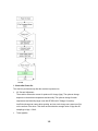
FLOW CHART FOR PRE-TRAINING
Service manager submits
registration for technician for the
D014/D015 series Instructor-led
Fail
Ricoh Service Education and
Development Division verifies
technician’s prerequisites
Pass
Technician completes pre-training
Service manager makes
assessment to see if technician is
prepared for course
Student attends class
7
Service manager may
wish to register the
technician for a digital
color copier or color
printer course
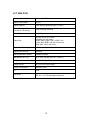
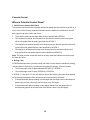
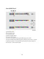
Differences Between The D014/D015
&
B132/B200 Service Manuals.
Detailed information, such as some replacement and adjustment
procedures, and detailed descriptions have been omitted from
this service manual. This is because the information is identical to
the previous model B132/B200.
Please refer to the B132/B200 Service Manual for those
procedures and descriptions omitted from this manual.
8
NEW FEATURES OF D014/D015
Responses to Requests for Improvement
This section describes changes that were implemented in response to requests for
improvement in the performance of the B132/B200.
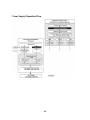
Improved Productivity
Copy Speed
Mode
B132/B200
D014/D015
D014: 60 cpm
K
B132/B200: 60 cpm
FC
B132/B181: 45 cpm
D014: 55 cpm
B200: 55 cpm
D015: 70 cpm
D015: 75 cpm
Copying speed has been improved due to:
1. PxP toner with a lower melting point.
2. Better fusing control. This was achieved with a more efficient ac power supply to
the fusing unit.
Shorter Warm-up Time
B132/B200
D014/D015
D014 NA: 90 sec.
300 sec.
D014/D015 EU: 75 sec.
D015 NA: 75 sec.
The shorter warm-up time was achieved by:
Adopting a sponge hot roller for fusing; the nip is wider, so the fusing
temperature is lower
Adopting an extremely thin heating roller used at lower temperature
221
Overall System
The system timing has been overhauled based on the B132/B200 base control
modules.
Improved Reliability
Longer Service Life of Developer
Servicing has been improved by extending the service life of the developer. This was
achieved by adopting a pre-mixing developer system. Toner and carrier are premixed in the STC (Soft Toner Cartridge with 90 wt% toner, 10 wt% carrier). The toner
and carrier are supplied together to refresh the developer already in the
development units. High image quality can be maintained for a greater length of time
with this system.
Better Stability of Image Density
Compared to the B132/B200, the consistency of the image coverage has been
dramatically increased. This was accomplished by the adoption of the singledirection development system.
B132/B200
The developer in the D014/D015 development unit is circulated in one direction.
This achieves better uniformity in the application of the toner to the developer
sleeve.
Compared to the B132/B200, this means less variation in image density from left
to right and from top to bottom on the output pages.
Ventilation: More Effective Cooling
10
The adoption of the PxP toner with its lower melting point means that the machine
must be adequately ventilated to keep the interior of the machine cooler.
1. Development Unit Cooling
A single fan (near the front door) draws in fresh air from outside the machine
and blows it across the heat sink.
An exhaust fan has been added to each development unit to draw hot air
away from the heat sink.
2. The heat pipe panels over the fusing unit have been overhauled.
B132/B200
The number of heat pipes has been increased and they have been
rearranged.
The heat sink cooling fan has been replaced with a fan with a more powerful
motor that can move more air.
11
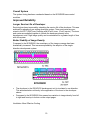
3. The used toner pipe path has been extended.
The air vent below the Y PCU has been enlarged so that it can handle a
greater volume of air. is the heat pipe, is the used toner conduit.
Air is drawn into the vent from the fan at the front door.
4. New cooling airflow duct
12
An air flow duct 1 has been added to the ITB cleaning unit to improve ventilation.
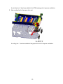
5. New cooling fan for the paper drive unit
A cooling fan
has been added to the paper drive unit to improve ventilation.
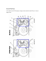
13
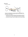
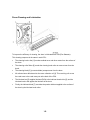
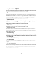
Paper Feed
1. Handling Thick Paper
As shown in the diagram above, the paper feed path has been changed. The
dotted lines show the shape of the paper feed path of the D014/D015, the solid
lines the path in the B132/B200.
The paper transport unit and the fusing unit entrance guide were both raised,
so the angle is much shallower. The change in the angle allows thick paper
to feed much easier. Even 300 g A4 LEF paper can now feed more efficiently.
The area where the paper contacts the transport belt has also been enlarged.
14
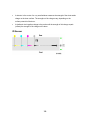
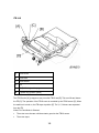
Paper Output
The amount of paper curl (compared with the B132/B200) has been reduced.
To reduce the amount of buckling of the paper in the paper path, the inverter
relay roller 3 feeds all paper at the same speed after it passes the de-curler. The
gap between the guide plates 1 was enlarged.
The curvature 2 of the turn in the paper path between the de-curler and the
junction gate has been enlarged.
Inverter relay roller 3 has been added.
15
Elimination of Pawl Marks on Prints
A new fusing belt stripper eliminates shiny stripper marks on prints.
A new stripper plate has been designed to strip copies that occasionally stick to
the fusing belt. The points of the stripper plate are flat PFA resin plates, not sharp
points.
The new PxP toner, which contains a new type of wax, separates more easily
from the belt so the sheet is less likely to stick to the fusing belt.
The new soft-sponge material of the hot roller also means that paper is less likely
to stick to the fusing belt.
16
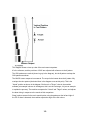
Fusing Lamp Rearrangement in the Heating Roller
The layout of the fusing lamps has been rearranged to ensure a more efficient
distribution of heat.
In the Heating Roller:
Lamp 1 heats the entire length of the fusing belt.
Lamp 2 heats only the ends of the fusing belt. (Used only for large paper sizes.)
Lamp 3 heats only the center of the fusing belt. (Used for smaller, thick paper
sizes; lamp 2 is not used.)
This allows better control of the heat applied to the fusing belt, based on the
requirements of the paper size and paper type selected for the job.
17
Reduction of Pressure on the Hot Roller
A new pressure roller lift mechanism has been adopted to raise the pressure roller
and keep it against the hot roller only while the machine is printing.
At the end of the job, the pressure roller is lowered and separated from the hot roller.
If the pressure roller remains pressed up against the soft sponge material of the hot
roller while the machine is idle, this could permanently warp the shape of the soft hot
roller and cause problems during image transfer from belt to paper.
Handling Thicker Paper
The D014/D015 can handle paper weights up to 300 g/m2 (110 lb Cover). This is a
significant improvement.
The time in the nip for thick paper (Thickness 2) with the B132/B200 was 80 ms. The
time in the nip for Thick 1 with the D014/D015 is 100 ms.
For thick paper:
The nip of the D014/D015 is wider than the nip of the B132/B200.
The line speed of the D014/D015 adjusts to slower speeds to match the
thickness of the paper.
Other modifications were done to allow handling thicker paper:
A guide mylar was added at the "turn" where the paper feeds from the paper
trays, to reduce the amount of bending on the leading edge of paper as it leaves
the tray.
The paper path from the bypass tray was changed to straighten the paper path
from feeding> registration> image transfer. This makes feeding thick A4 LEF
much easier.
The paper path of the duplex unit was modified slightly to reduce bending in
paper at the "turn", and the junction gate solenoid has more strength to handle
thicker paper.
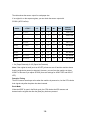
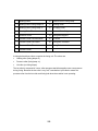
The table below shows significant improvement in handling thicker paper.
Feed Station
Paper Tray
Bypass
B132/B200
D014/D015
52.3 to 127 g/m2
52.3 to 216 g/m2
14 to 47 lb. Cover
14 to 80 lb. Cover
52.3 to 256 g/m2
52.3 to 300 g/m2
14 to 94 lb. Cover
14 to 110 lb. Cover
18
UP
70%
17%
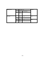
Feed Station
Duplexer
B132/B200
D014/D015
64 to 127.9 g/m2
64 to 163 g/m2
17 to 47 lb. Cover
17 to 90 lb. Cover
19
UP
27%
Operability
Some improvements have been done for the operator.
Handling Paper Jams
The B132/B200 displayed only a message to alert the operator about a jam or
double-feed. The D014/D015 has a fully animated system to guide the operator
step-by-step through jam removal.
Easier Use of Paper Tray End Fence
With the B132/B200, the operator must push and hold down a side lever while
moving the end fence. With the D014/D015, the operator need only press the end
fence slightly to move it to the position for a standard paper size.
New Arrow Indicator on Side Fence Lever
An arrow indicator embossed on the side fence reminds the operator where to push
to release and move the side fence.
Image Quality Improvement
This section describes the changes that have been implemented to improve image
quality for the D014/D015.
Adoption of Single-Direction Developer/Toner Supply
The adoption of the single-direction developer/toner supply method has resulted in
the following improvements.
Uniformity of Image Density
With the B132/B200, there are minor problems with images becoming faint (front
to back) because the agitator moves the toner front to back. There were
variations of less than 25% with the B132/B200, but this has been reduced to
less than 15% with the D014/D015. This reduction was made possible with the
adoption of a one-direction development system in the development units.
Stabilization of Image Quality
B132/B200 image quality shows some repeat density fluctuation (0.15), but this
has been reduced with the D014/D015. The improvement was achieved by using
a stable-density development system.
20
Stabilization of High Quality Images
With the B132/B200, it was found that there was some image deterioration in
high quality images created with high duty coverage during continuous paper
feed. (image quality deteriorated after about 20K copies). The improvement was
achieved by adoption of the developer/toner pre-mixing system.
Adoption of New PxP Toner
The adoption of the new PxP toner has achieved the following dramatic
improvements in image quality.
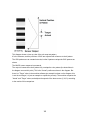
Granularity, Reproduction of Dots
B132/B200
B132/B200
The difference in the granularity of B132/B200 pulverized toner (6.8 µm) and
D014/D015 PxP toner (5 µm) toner has a significant effect on image quality. The
D014/D015 toner with toner granules of smaller diameter reproduces a much better
image with dots of 0.4, compared with 0.5 of the B132/B200.
21
Sharpening Text
B132/B200
There were requests from customers for sharper reproduction of text characters
(reducing the "halo" effect around text characters). Better text reproduction was
achieved with better control over the rotation of the development roller and drum and
changing the ratio of their rotation. The drum and development roller are driven by
separate motors in the D014/D015.
Blurring at the Trailing Edges of Images
Many customers requested elimination of the blurring at the trailing edges of
images. This problem was solved with the development rollers and OPC drums
rotating slightly slower relative to line speed.
22
Elimination of Shiny Pawl Marks on Prints
Many customers requested elimination of the shiny streaks at the trailing edges of
sheets that were caused by the strippers that removed paper from the fusing belt.
The problem of paper separation from the fusing belt was solved in two ways:
The design of the fusing unit was changed. The hot roller [A] is composed of soft
sponge. When the pressure roller [B] presses into the hot roller from below this
creates a much wider nip. The paper enters the wider nip and when it exits
the nip at the curvature of the nip points the paper downward. This improves
separation of the paper from the fusing belt.
The fusing belt strippers were replaced by a new stripper plate equipped with flat
soft plates (not points) that will not leave marks on the paper.
23
Comparison of Changes in Basic Operation
D014/D015
Copy
Speed
D014
B132/B200
FC: 55 cpm,
B132/B200
B&W: 60 cpm
FC: 45
cpm,
B&W 60
cpm
D015
FC: 70 cpm
B132/B200
B&W: 75 cpm
Warm-up
Time
EU/AP
Less than 75 sec.
NA
D014/D015
< 300 sec.
< 90
sec.
D014/D015 < 75 sec.
First
Copy
FC
D014/D015
D014/D015
6.4 sec.
B&W
D014/D015
D014/D015
4.9 sec.
Power
NA
Specificat
ions
EU/AP
7.5
sec.
7.5 sec.
5.7
sec.
6.5 sec.
D014: 120V 16A 60 Hz
120V
D015: 208-240V 12A
60 Hz
16A 60 Hz
220-240V 12A 50-60
Hz
220 to 240V
24
8.7A 50/60 Hz
FC: 55
cpm B&W:
60 cpm
NA
Max
Power
Consump
tion
EU/AP
D014: Less than
1920W
< 1920 W
D015: Less than
2400W
D014/D015: Less than
2400W
< 1920 W
Line
Speed
Normal D014: 282 mm/s
Paper D015: 352.8 mm/s
B132/B200 282 mm/s
Thick D014/D015: Thk 1: 176.4 mm/s,
Paper
Thk 2, Thk 3: 141 mm/s
OHP D014/D015 141 mm/s
B132/B200: 141 mm/s
B132/B200 100 mm/s
Comments
Warm-up Time. The warm-up time is much faster. This is achieved with the
newly designed fusing unit and low melting-point toner.
First Copy. The first copy time is much faster due to the adoption of the new
fusing unit and low melting-point toner.
25
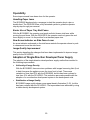
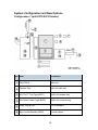
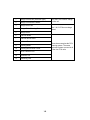
System Configuration and New Options
Configuration 1 (with D373/D374 Finisher)
No. Item
Comments
D014/D015
Main unit
Tandem Tray
Built into main unit
A3/11"x17" Tray Type (B331)
Option for tandem tray
Tab Sheet Holder Type (B499)
Option for universal tray
Copy Tray (B756)
For no finishers
Key Counter Bracket (B452)
Counter option
26
No. Item
Comments
Key Counter Interface Unit Type
(A) (B870)
Board required for key counter
Card Reader Bracket (B498)
Counter option
LCT 4000 (D350) *1
Only one of these options can be
installed.
A4/LT LCT (B473)
LCT Adapter (B699)
Required for LCT B473
LG Unit for A4/LT LCT (B474)
Option for LCT B473
Z-Folding Unit ZF4000 (B660) *1
Cover Interposer Tray (B704)
For D373 (2000-sheet), D374
(3000-sheet) finishers only. Only 1
tray. Cannot be installed with Mail
Box (B762).
Finisher SR4020 (D373) *1
2000-sheet finisher, 50 staple,
Booklet folding and stapling
Finisher SR4010 (D374) *1
3000-sheet finisher, 50 staple,
corner stapling only
Punch Unit (B702)
For either finisher D373 or D374
Output Jogger Unit (B703)
For either finisher D373 or D374
Mail Box CS391 (B762)
For D373 (2000-sheet), D374
(3000-sheet finishers only). Cannot
be installed with Cover Interposer
Tray (B704)
*1 New options for this machine.
27
Configuration 2 (with B830 Finisher)
No. Item
Comments
D014/D015
Main unit
Tandem Tray
Built into main unit
A3/11"x17" Tray Type (B331)
Option for tandem tray
Tab Sheet Holder Type (B499)
Option for universal tray
Copy Tray (B756)
For no finishers
Key Counter Bracket (B452)
Counter option
Key Counter Interface Unit Type
A (B870)
Board
28
No. Item
Comments
Card Reader Bracket (B498)
Counter option
LCT 4000 (D350
Only one can be installed.
A4/LT LCT (B473)
LCT Adapter (B699)
Required for LCT B473 to adjust
height.
LG Unit for A4/LT LCT (B474)
Option for LCT B473
Cover Interposer Tray CI 5000
(B835)
Two source trays. Can be installed
with 3000-sheet finisher B830 only.
Z-Folding Unit ZF4000 (B660)
Can be installed with D373, D374,
B830 finishers.
Finisher SR5000 (B830)
3000-Sheet finisher, 100 staples,
jogger standard.
Finisher Adapter (D375)
For Finisher B830
Punch Unit PU 5000 (B831)
For 3000-sheet finisher B830 only.
29
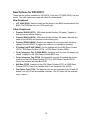
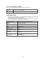
New Options for D014/D015
These are the options available for D014/D015. Only the LCIT 4000 (D350) is a new
model. The other options are used with other Ricoh machines.
New Peripheral
LCT 4000 (D350). New but based on the design of the B834 introduced with the
B286. The D350 has only one 2,000 sheet tray.
Other Peripherals
Finisher SR4020 (D373). 2000-sheet booklet finisher (50 staple). Capable of
both corner and booklet stapling.
Finisher SR4010 (D374). 3000-sheet booklet finisher (50 staple). Basically the
same as the SR4020 but features corner stapling only.
Finisher SR5000 (B830). Requires an adapter kit to accommodate the faster
speed of the D014/D015. A jogger unit is built-in (no installation required).
Z-Folding Unit ZF4000 (B660). Can be installed with the 2000-Sheet Finisher
(D373), 3000-Sheet Finisher (D374), or 3000-Sheet Finisher (B830).
Cover Interposer Tray CI 5000 (B835). Equipped with two trays for feeding slip
sheets. Installed on the 3000-Sheet Finisher B830 only.
Cover Interposer Tray (B704). Equipped with one tray for feeding slip sheets.
Installed on the 2000-Sheet Finisher (D373) or 3000-Sheet Finisher (D374).
Cannot be installed with Mail Box B762.
Mail Box (B762). Installed on the 2000-Sheet Finisher (D373) or 3000-Sheet
Finisher (D374). Cannot be installed with Cover Interposer Tray (B704).
Fax Option Type C7500. The base fax unit can accommodate both G3 and G4
boards, but only G3 will be available overseas. (The G4 option will be available
only in Japan.)
30
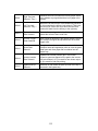
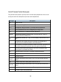
MFP Options (Listed Alphabetically)
Option
Prod. No.
Config.
Bluetooth Interface Unit Type 3245
B826
Board
Browser Unit Type D
D377
SD Card
Copy Connector Type 2105
B328
Board
Copy Data Security Unit Type F
B829
Board
Data Overwrite Security Unit Type H
D377
SD Card
Fax Option Type C7500
D336
Board
File Format Converter Type E
D377
Board
G3 Interface Unit Type 7500
D357
Board
Gigabit Ethernet D377*1
D377
Board
HDD Encryption Unit Type A
D377
SD Card
IEEE 1284 Interface Board Type A
B679
Board
IEEE802.11a/g Interface Unit Type J
D377
Board
IEEE802.11g Interface Unit Type K
D377
Board
Java VM Card Type E
D377
SD Card
PostScript 3 Unit Type C7500
D378
SD Card
Printer/Scanner Unit Type 7500
D376
SD Card
*1: The EFI (Fiery) Controller currently under development will be connected via the Gigabit
Ethernet Board.
31
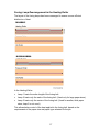
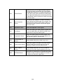
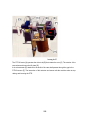
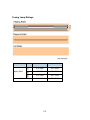
Appearance of Actual Configurations
Configuration Sample for General Office Customers
No. Item
Comments
D014/D015
Main unit
LCT 473
Option
Finisher SR4020 (D373)
2000-sheet finisher, 50 staple, Booklet
folding and stapling
32
Configuration Sample for Light Production Customers
No. Item
Comments
D014/D015
Main unit
LCT 4000 (D350)
New option.
Cover Interposer Tray CI 5000 (B835)
Two source trays.
Z-Folding Unit ZF4000 (B660)
Finisher SR5000 (B830)
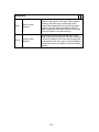
More Details About Design Changes
This is a summary of the most important design changes in the D014/D015. For
more details, please refer to Section 6 of the D014/D015 manual.
33
PCU (Photoconductor Unit)
Developer Filling, Replacement
B132/B200
The B132/B200 uses a plastic developer container installed inside the PCU. With the
D014/D015, the developer is poured from a newly designed developer bottle
attached to the front end of a PCU. After filling, the bottle is detached and discarded.
With the D014/D015, it is not necessary to remove the PCUs from the machine in
order to fill them with developer.
PCU Design
The PCU units have been redesigned. In the previous model, all the PCUs had the
same structure. In this machine, the K PCU employs the charge corona wire system
that is commonly used in other machines. The other PCUs (Y, C, M) use charge
rollers just like the B132/B200.
Different Designs of YCM PCU and K PCU
34
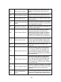
1
Charge Corona Unit (Scorotron type)
2
Charge Corona Wire Cleaner
3
Charge Roller Unit
4
Charge Roller Cleaning Roller
5
Charge Roller
6
Lubricant Blade
7
Lubricant Brush Roller
8
Lubricant Bar
9
Cleaning Blade
10
Cleaning Brush Roller Flicker
11
Toner Collection Coil
12
Collection Coil
13
Quenching LED
Only the K PCU uses a
charge corona unit.
The Y, M, C PCUs use
charge rollers.
These items comprise the
PCU cleaning system. The
same parts and system are
used in all of the four PCU
units.
The OPC drums of the B132/B200 and D014/D015 are not interchangeable.
35
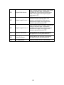
Potential Sensors
Potential Sensor Position
The drum potential sensors (x4) no longer reside inside the PCUs. They are
attached to the main machine just above each PCU . This new arrangement
keeps the potential sensors free of toner and dust during servicing.
36
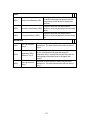
Development Unit
Cross-Section of Development Unit
B132/B200
D014/D015
B132/B200
1 Heat Sink
Heat Sink
2 Doctor Blade (t=2.0)
Doctor Blade (t=2.0)
3 Development Roller
Development Roller
4 Entrance Seal
Entrance Seal
5 Drum (diameter 60)
Drum (diameter 60)
6 Toner Collection Auger (dia. 22) Developer Auger 1 (dia. 18)
7 Mixing Auger (diameter 22)
Developer Auger 2 (dia. 18)
8 Supply Auger (dia. 22)
---
9 Used Toner Auger
---
10 Filter
-----
Developer Cartridge
37
Note: The D014/D015 does not contain a developer cartridge. The PCU is filled with
developer from a newly designed bottle. The PCU does not need to be removed
from the machine in order to fill it with developer.
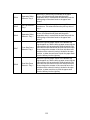
External View of Development Unit
B132/B200
D014/D015
B132/B200
1
Filter
2
Heat Sink
Heat Sink
3
Entrance Seal
Entrance Seal
4
Development Roller (diameter
25)
Development Roller (diameter 25)
5
Toner Supply Port
Toner Supply Port
6
---
---
Development Cartridge
Note: The D014/D015 does not contain a developer cartridge. The PCU is filled with
developer from a newly designed bottle. The PCU does not need to be removed
from the machine in order to fill it with developer.
38
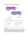
Toner/Developer Flow Inside the Development Unit
B132/B200
D014/D015
B132/B200
1
Collection Auger (dia. 22)
2
Development Roller (diameter 25)
Development Roller (diameter 25)
3
Supply Auger (dia. 22)
Developer Auger 1 (diameter 18)
4
Mixing Auger (dia. 22)
Developer Auger 2 (diameter 18)
5
Toner Supply Port
Toner Supply Port
The one-direction flow of developer in the D014/D015 development unit improves
image quality.
In the D014/D015, the path for fresh developer is separate from the path that collects
excess toner from the doctor blade that smoothes the toner that will be applied to the
drum. Compare with the B132/B200 above where this excess toner mixes with fresh
toner. The D014/D015 achieves a more even coating of toner on the drum and uses
only fresh toner/developer. This means the density of the image is more uniform.
39
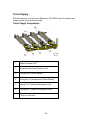
Toner Supply
With the exception of a few minor differences, D014/D015 uses the same toner
supply system as the previous model.
Toner Supply Components
1
Waste Developer Coil*1
2
Horizontal Used Toner Transport Coil
3
Cooling Fan 2 (Doctor Blade)*1
4
Cooling Duct 2 (Development Doctor Blade)*1
5
Cooling Fan 1 (Below Development Unit)
6
Cooling Duct 1 (Below Development Unit)
*1 These are new items.
40
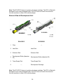
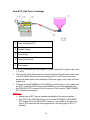
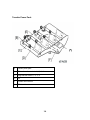
New STC (Soft Toner Cartridge)
1
Toner Cartridge (STC)
2
Flexible Tubing
3
Toner Pump
4
Toner Pump Clutch
5
Sub Hopper
Four STCs are set in the toner hopper. They are inserted left to right in this order:
Y, C, M, K.
The new PxP toner (high-resolution oil-less Polyester Polymerization toner) used
in the D014/D015 has a much lower melting point. For this reason, fans and
ducts have been added to the faceplate of the toner supply unit to keep the toner
supply cool.
The toner for the B132/B200 and D014/D015 is not the same, so this means that
the STCs of the D014/D015 and the B132/B200 are not interchangeable. Also,
the D014/D015 STC contains 90 wt% toner and 10 wt% carrier. The B132/B200
STC contains no developer.
Neither type of STC can be inserted accidentally in the wrong machine.
The STC for the D014/D015 does not fit into the B132/B200; a B132/B200
STC does not fit in the D014/D015. However, it is possible to set the wrong
type of STC and close the toner hopper even if the wrong type of STC is
installed.
41
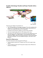
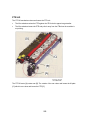
Transfer Unit (Image Transfer and Paper Transfer Units)
ITB Unit
There are some changes in the transfer unit:
The PTR lift mechanism [1] has been redesigned. This is the mechanism that
keeps the PTR unit against the ITB during belt-to-paper image transfer and
lowers the unit when the transfer unit is not operating.
A lubricant brush [2] has been added to the lubricant bar assembly..
The toner transport agitator [3] in the ITB cleaning unit [4] is new.
The cleaning unit of the ITB (shown at the lower left in the diagram above) has
also been changed. Two cleaning blades, one cleaning brush roller, and a
lubricant bar (ZnSt) comprise the cleaning mechanism. These cleaning blades
and roller are PM parts. For a more detailed description, see Section 3 and
Section 6.
New PTR Lift Mechanism
The PTR lift mechanism raises and lowers the PTR unit.
The lift mechanism raises the PTR against the ITB for belt-to-paper image
transfer.
The lift mechanism lowers the PTR and pulls it away from the ITB when the
machine is not printing.
42
PTR Lift Mechanism
The PTR lift motor [A] rotates cam [B]. The rotation of the cam raises and lowers the
lift plate [C], which in turn raises and lowers the PTR [D].
This mechanism is necessary because the roller in the ITB unit that opposes the
PTR is made of a softer material than in the B132/B200. The PTR will deform this
roller if it always contacts it.
43
Increased Durability of Paper Transfer Roller
B132/B200
PTR
Cleaning Brush Roller
Cleaning Blade
Lubricant Bar
Lubricant Brush Roller (D014/D015 only)
1. Reduction of Scratches on PTR
Scratches on the surface of the PTR caused by foreign particles are a problem
with the B132/B200. Also, there is some scratching on the belt caused by the
lubricant bar being in direct contact with the roller
In the D014/D015, the lubricant bar does not touch the roller. The lubricant brush
roller picks up the lubricant (ZnSt) from the lubricant bar and applies the
lubricant to the surface of the roller. This dramatically reduces the amount of
scratching on the surface of the PTR and extends the life of the roller and the
cleaning unit parts.
44
2. PTR layer cracking
The service life of the PTR has been extended to 600K.
Cracking between the layers of the PTR occurs in the B132/B200, resulting in its
short service life: 150K. This cracking is caused by uneven pressure at the nip of
the PTR and paper transfer bias roller above.
To equalize this pressure at the nip between the ITB bias roller (opposite the
PTR in the ITB) and the PTR in the D014/D015, the ITB bias roller of the
D014/D015 is composed of softer material. This extends the service life of the
D014/D015 PTR to 300K.
45
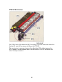
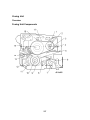
Fusing Unit
A fusing belt and three fusing rollers comprise the new fusing unit. The rollers are
the heating roller (fusing lamps x3), pressure roller (fusing lamp x1), and hot roller
(no fusing lamps). The hot roller is composed of a new, soft sponge material that
creates a wider nip band where a more even pressure is applied for fusing.
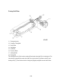
General Layout of Fusing Unit
46
1. Heating Roller
10. Pressure Roller Fusing Lamp
2.
Heating Roller Fusing Lamps
x2
11. Cleaning Roller
3.
Heating Roller Fusing Lamp
x1
12. Oil Supply Roller
4. Heating Roller Thermistor
13. Pressure Roller Strippers
5. Entrance Guide
14. Fusing Belt Strippers
6.
Pressure Roller Lift
Mechanism
15. Hot Roller
7. Pressure Roller Lift Sensor
16. Fusing Belt Thermistor
8. Pressure Roller Thermistor
17. Fusing Belt
9. Pressure Roller
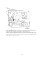
New Pressure Roller Lift Mechanism
A new pressure roller lift mechanism raises and lowers the pressure roller. When
fusing starts, the pressure roller lift motor switches on and raises the pressure roller
against the hot roller above. At the end of the job, the motor reverses and lowers the
pressure roller away from the hot roller. The hot roller and pressure roller remain
separated while they are idle. This prevents the pressure roller and hot roller from
warping, and prolongs their service lives.
47
Motors
The following illustrations show the positions of motors around the drum, as viewed
from the rear.
Front, Rear View of Drum Cleaning, Development, Drum
Motors
1.
Drum Cleaning Motors x4*1
2.
Development Motors x4*1
3.
Drum Motors x4
4.
Development Coil Shaft
5.
Drum Cleaning Motor Shaft
6.
Drum Motor Shaft
7.
Development Roller
*1: New items
48
Changes to Improve Torque Transmission Efficiency
The size of color registration errors has been reduced with changes in the design of
the drum motor.
Drum Motor Shaft
B132/B200
In the B132/B200, the drum motor shaft and drum motor are separate components.
In the new D014/D015 drum motor, however, the shaft and motor are permanently
connected. This direct-drive arrangement improves the performance of the drum
motor and shaft. Also, for the D014/D015 drum motor, the rotation wave fluctuation
of has been reduced by 30%.
In addition to this change in drum motor design, the FB (Feedback) control system
has been improved to reduce color registration errors.
49
FB Control
The average incidence of color registration errors on the ITB has been reduced. This
has been achieved by improvement in the hardware (FB electrical components) and
software (control algorithms).
50
ITB Drive, PTR, Fusing/Exit Motors
ITB Drive Motor
PTR Motor
Fusing/Exit Motor
Paper Transport Belt Drive Shaft
Fusing Unit Drive Shaft
Duplex Unit Drive Shaft
ITB Cleaning Unit Drive Shaft
Used Toner Drive Shaft
51
K/YMC Lift, Used Toner Motors
Black ITB Roller Lift Motor*1
Diagonal Used Toner Coil Motor
ITB Lift Motor
Horizontal Used Toner Coil
*1: New item: Lowers the black image transfer roller away from the ITB and PCU drum during
automatic developer installation. Not used at this time (Oct. 2007).
52
Controller Board
The number of board slots has been reduced to three.
The number of SD card slots has been reduced to two. (A system SD card is no
longer required. The system firmware resides on the controller board.)
A new fan has been added to the GW controller board.
Small Changes
This is a quick summary of small changes in the D014/D015.
Filter Box Cover. There are new filter boxes on the back of the machine. There
are now three filter boxes.
Paper Tray Handles. A new tray handle design has been adopted for the
D014/D015. Also, the shape and operation of the end fence has changed.
Motherboard. There is no motherboard in the D014/D015
Breaker Switch. This machine does not have a breaker switch that requires
testing at installation.
Peltier Unit. The Peltier unit has been removed. The D014/D015 does not have
a Peltier unit.
Paper Feed Unit. A mylar has been added to facilitate feeding thicker paper.
Bypass Tray. The operation of the side fences is much smoother.
Process Control. The number of steps in process control has been reduced.
Also, MUSIC processing and process control adjustment are executed at the
same time at power on, so that the machine enters standby mode within a
shorter length of time.
Fans. Fans and ducts have been added on the faceplate that covers the toner
supply unit. This new arrangement keeps the temperature lower. (The new PxP
toner has a much lower melting point.)
Functions disabled during warm-up. These functions have been disabled
during warm-up:
1. SP3820 (Manual Procon)
2. Auto Color Calilbration (User Tools)
3. Color Registration (User Tools)
53
Notes About Servicing
These are notes about the differences in servicing the D014/D015 machine. These
changes are described in detail in Section 3.
1. Toner/developer and drum replacement.
The STCs of the B132/B200 and D014/D015 are not interchangeable. The
D014/D015 uses the new PxP toner and the developer bottle has a new design. The
B132/B200 STCs cannot be inserted in the D014/D015. The OPC drums of the
B132/B200 and D014/D015 are also not interchangeable.
2. Scanner Unit.
The shapes and sizes of some of the scanner unit boards have changed to make
them easier to service. Also, the arrangement of the APS sensors has been changed.
The fan has been removed from the left side of the scanner unit.
3. Laser Unit.
The SP codes for the laser unit (provided on a decal attached to the laser unit) have
changed. Also, the polygon motor harness connector has been modified.
4. PCU
The OPC and development unit must be separated for servicing.
The K and YMC PCUs are not the same. The K unit uses a charge corona unit
and the YMC units use charge rollers to charge the OPC drum.
The charge roller and cleaning roller are much easier to remove.
The PCU stand (stored under the machine) is still required for servicing. The
bottom of the D014/D015 PCU stand stores only one jig (required for developer
replacement).
The PCU stand is required for servicing, because it provides two important
functions: 1) It protects the drum from damage and exposure to light while the
PCU is out of the machine, and 2) It keeps the OPC aligned correctly so the
development unit can be reattached.
The PCU stand must remain attached to the bottom of the main machine at the
customer site.
The shape of the D014/D015 PCU stand is not the same as the
B132/B200 stand, so these stands are not interchangeable. Using the
B132/B200 PCU stand with a D014/D015 PCU could damage the drum.
The cleaning blades of the K PCU and YCM PCUs are not identical. One blade
is designed for use with the K PCU and another type for the YCM PCUs. Each
blade is marked "K" or "MCY" to identify the blade type.
The lubricant bar of the K PCU and YCM PCU are identical. However, the
lubricant bar “units” are not the same. The K PCU is marked with a "K" to
54
distinguish it from a YMC lubricant bar unit which is not marked. (The lubricant
bar itself, however, can be used in either unit.)
A D014/D015 PCU consists of both the drum unit and the development unit.
However, unlike a B132/B200 PCU unit that could be opened, with the
D014/D015 the drum unit and development unit must be separated for servicing.
Installation of a new PCU. This procedure has changed. More SP code settings
are required. These SP codes are provided on a sheet with each new PCU unit.
When you dust the surface of a new drum, use only Lubricant Powder
B1329700 (specially designed for this machine). Do not use the yellow
toner from this machine because it contains developer. The developer will
damage the drum and ITB.
Developer replacement. This is a new procedure. A jig stored on the bottom of
the PCU stand is required to lock the development roller so that the old
developer can be removed from the PCU.
The rectangular developer packs of the B132/B200 have been replaced with
newly designed bottles.
Filling and replacing developer: These are new procedures.
TD sensor. The TD sensor is of new design and extremely sensitive (calibrated
at the factory). This TD sensor cannot be replaced separately.
5. ITB unit
There are some minor changes in the servicing of the ITB unit. One connector has
been removed, and the shapes of some parts have changed. The new ITB unit has
two cleaning blades. Both blades are PM parts.
When you dust the surface of a new ITB, use only Lubricant Powder
B1329700 (specially designed for this machine). Do not use the yellow toner
from this machine, because it contains developer, and this will damage the
drum and ITB.
6. PTR Unit
The PTR unit has a new lift mechanism and the lubrication bar is much easier to
remove. Removing dust from the PTR unit is also much easier.
55
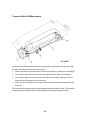
7. Fusing Unit. The fusing unit is new.
There is a new lock arm at the back of the unit that must be released before the
fusing unit can be removed. Disassembly of the fusing unit is much easier.
Important: There are two fusing units: a 120V unit and 240 V unit.
The fusing lamp connectors of the 120V unit are BLUE, those of the 240V unit
are PINK.
If the wrong type of fusing unit is installed in the machine, the machine will detect
this and issue a warning. There is no danger of damaging either the fusing unit
or main machine.
The B132/B200 and D014/D015 fusing belts are not interchangeable. The
D014/D015 belt is longer.
8. Boards. The layout of the main boards has changed.
There is no motherboard.
The AC boards of the 120V and 240V machines are different. The boards are
clearly marked "100V" or "200V" in the center of the board to prevent installing
the wrong type of board.
The controller board must be removed before the IPU/VBCU boards can be
removed.
9. HDD Removal
The HDD must be reconnected correctly. If the HDD is connected incorrectly, the
machine will issue an HDD error at power on. This will not harm the HDD or corrupt
data on the disk. Just power the machine off and reconnect the HDD correctly.
10. Motors
Drum motor replacement is much easier (a jig is no longer required to lock the
motor shaft.)
The development motor and drum cleaning motor can be removed separately.
The position of the paper transfer motor has changed.
The shape of the image transfer motor has changed.
56
Detailed Summary of Changes
External Appearance, Operation Panel
The operation panel includes a WVGA (Wide Video Graphic Array) Color TouchPanel
External covers and paper trays are newly designed. Paper trays adopt a new
design.
Controller Box
New design. Layout of internal components and PCBs has been changed.
Also, an FCU (Fax Control Unit) is a new option.
Main Frame Configuration, Ventilation
New cooling fans for the development units, and a new cooling fan near the Y
PCU on the left side of the machine.
A heat sink (in the form of a pipe) has been added to the fusing unit to improve
efficiency of cooling.
Engine Drive Mechanisms
PTR motor. A reduction gear has been added to the DD (Direct Drive) motor and
transfer belt cleaning has been improved.
The ITB encoder sensor (FB or Feedback sensors), two separate sensors on the
B132/B200, have been combined into one sensor to reduce cost and improve
efficiency.
The used toner horizontal transport path has been extended.
Along with changes in component layout around the drum, new drum cleaning
motors have been added. Each drum cleaning roller is now driven by a separate
motor.
The linkage of the OPC drum motors has been improved in order to shorten
warm-up time and to improve the precision of drum rotation.
The design of the output drive shaft used in each development unit has been
changed to reduce wear on the development unit gears.
The drum potential sensors (x4) have been removed from the PCUs and
mounted in the main machine, one above each PCU.
Exposure
Along with improvement in the line speed, the CCD, exposure lamp, scanner
motor have been modified.
In order to reduce costs, newly designed lenses and an ADF exposure glass
have been adopted for this machine.
57
Laser Writing
In line with the improvement in the line speed, the speed of the polygon motor
has been increased. (This follows similar improvement in other machines.)
Paper Feed
In response to requests for better handling of thick paper, some changes have
been done within the restricted range of the present B132/B200 layout.
Some minor changes have been done in the paper feed trays (developed based
on B132/B200) to allow feeding thicker paper.
There are no changes in paper registration.
Some small changes have been done within the limitations of the present design
of the duplex/inverter unit for better handling of thicker paper and for reduction of
paper curl.
Development, Toner Supply
Adoption of high-resolution oil-less polyester polymerization toner (hereafter
"PxP toner").
A new STC (Soft Toner Cartridge) that contains toner pre-mixed with 10 wt%
carrier is used to fill the development units.
A new single-direction development method has been devised to reduce uneven
image density on a single page and reduce developer deterioration.
In order to improve the precision of heat reduction, an aluminum steel sleeve has
been adopted. Also, Vs/Vp have been reduced to correct blurring at the trailing
edges of solid images
Automatic developer installation.
Drum Charge, Cleaning
The following measures have been adopted to deal with the problems of blade
service life and dirty OPC drums, caused by the slippage of PxP toner on the ITB:
The K PCU uses the Scorotron Charge Method that uses a self-cleaning charge
corona wire, and an auxiliary cleaning brush.
The other PCUs (Y,M,C) use charge rollers with retractable cleaning rollers and
auxiliary cleaning brushes.
58
Image Transfer
The following measures have been adopted to deal with the problems of blade
service life and dirty OPC drums, caused by the slippage of PxP toners on the ITB:
A lubrication brush roller and lubricant counter blade (both for ZnSt) have been
added downstream of the counter blade and brush system of the B132/B200 ITB
cleaning system.
Paper Transfer
Reducing the amount of toner in order to deal with the problem of the short
service life of the cleaning blade, caused by the slippage of PxP toners on the
ITB.
Reverse bias is applied in the intervals between sheets on the ITB.
A new lift device has been designed to raise and lower the PTR (raise it during
paper transfer and lower it away from the ITB and bias roller when the machine
is idle).
Fusing
The fusing unit employs a halogen-belt design (halogen fusing lamps with fusing
belt) in order to shorten the warm-up time to less than 75 to 90 sec.
The fusing unit employs a sponge hot roller designed for a higher line speed and
better grip at the nip, and also employs a new pressure roller mechanism that
keeps the pressure roller separated from the hot roller when the machine is idle
(this prevents warping of the soft sponge of the hot roller).
The effect of the paper pointing downward as it exits the nip between the hot
roller and pressure roller improves separation and reduces the streaking on the
copies.
Process Control
The length of time to complete process control is much shorter.
The number of ID sensor patterns has been reduced.
The precision of the TD sensor has been improved.
OPC Drums
Adoption of the charge corona system for the K PCU improves resistance to
nitrogen oxides (NOx) in the air.
Toner
The new PxP toner used in the machine has a lower melting point. This allows a
shorter warm-up time, reduces the amount of heat required for fusing, and
achieves more even density in images.
59
60
SPECIFICATIONS
61
62
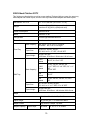
SPECIFICATIONS
Specifications
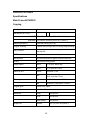
Main Frame D014/D015
Copying
Configuration
Console
Dimensions (w x d x h)
No ARDF 750 x 850 x 1050 mm (29.5 x 33.5 x 41.3 in.)
With ARDF 750 x 850 x 1230 mm (29.5 x 33.5 x 48.4 in.)
Weight (with ARDF)
Less than 298 kg (655.6 lb)
Original Scanning
Flatbed with moving 3-line CCD array, image scanning
Copy Process
4-drum dry electrostatic transfer system with internal
transfer belt
ARDF
Standard
Development
Dry dual-component magnetic brush development
Fusing
Oil-less belt fusing system
Engine speed
D014
FC 55 cpm, BK 60 cpm
D015
FC 70 cpm BK 75 cpm
EU/AP
Less than 75 sec.
NA
D014: Less than 90 sec.
D015: Less than 75 sec.
FC
D014/D015: Less than 7.5/6.4 sec.
BK
D014/D015: Less than 5.7/4.9 sec.
Warm-up time
First copy time
Original types
Sheet, book, object
Max. original size
A3, 11" x 17"
Resolution
Copy
600 dpi 4-bit
Print
600 dpi 4-bit
Scan (Send)
600 dpi 8-bit
Default
297 (+4) x 457 mm (Note 1)
Image Size
63
Max.
297 (+4) x 600 mm (Note 2)
Note 1: Size depends on the D014/D015 application "+4" not guaranteed.
Note 2:
Size depends on the D014/D015 application "+4" not guaranteed.
Setting with SP mode is required.
The max. setting cannot be selected if the SR5000 is installed.
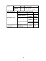
64
Magnification
Zoom
Paper capacity (Number of
sheets calculated with 80 g/m 2
20 lb bond paper)
NA
7 Reduction, 5 Enlargement: 93%, 85%,
78%, 73%, 65%, 50%, 25%,121%, 129%,
155%, 200%, 400%
EU/AP
7 Reduction, 5 Enlargement: 93%, 82%,
75%, 71%, 65%, 50%, 25%, 115%, 122%,
141%, 200%, 400%
25% to 400%
Tray 1
1,100 x2
2,200
Tray 2
550
550
Tray 3
550
550
Bypass
100
100
Copier
Capacity
3,400
With LCIT
4,000
7,400
NA
11" x 17", 8½" x 14" SEF,
8½" x 11" LEF/SEF
EU/AP
A3/A4 SEF, B4 SEF, A4/B5 LEF/SEF,
8½ " x 13" SEF (8K, 16K available
with SP mode)
NA
11" x 17", 10" x 14", 8½ x 14" SEF
8½" x 11", 5½" x 8½" SEF/LEF
7¼" x 10½", A3 SEF
A4 SEF/LEF
EU, Asia
A3, B4 SEF
A4, B5, A5, B6 SEF/LEF
8½" x 13", 8K SEF
16K SEF
Original size detection:
exposure glass
Original size detection (ARDF)
65
Paper weight
Output capacity
Power
Max. power consumption
Counter
Counterfeit prevention
Tray 1
52.3 – 216 g/m 2
14 Bond– 80 lb Cover
Tray 2
52.3 – 216 g/m 2
14 Bond– 80 lb Cover
Tray 3
52.3 – 216 g/m 2
14 Bond– 80 lb Cover
Bypass
52.3 – 300 g/m 2
14 lb Bond– 110 lb Cover
Duplex mode
64 – 163 g/m2
17 lb Bond – 90 lb Index
500 sheet (A4, 8½" x 11") (with copy tray)
NA
D014: 120V 60 Hz 20A
D015: 208 to 240V 50 60 Hz 10A
EU/AP
D014: 220V to 240V 50-60 Hz 10A
NA
Less than 1920 W
EU/AP
Less than 2400 W
NA
Electric counter, mechanical counter x2
EU/AP
Electric counter, mechanical counter x1
Bill recognition, invisible marking function
66
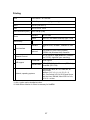
Printing
CPU
Intel Pentium – M 1.46 GHz
RAM
1536 MB (shared with copying, scanning)
HDD
320 GB (160 GB x 2)
PDL
RPCS, PCL5c, PCL6
Print Resolution (max.)
600 x 600 dpi (4-bit)
Fonts
Standard
48 PCL fonts
Option
With PS3, 136 Adobe PostScript Type 1 fonts
Standard
Ethernet RJ-45, 10-BaseT, 100BaseTX, USB
2.0
Options*1
IEEE1284 ECP, IEEE1394 (FireWire),
IEEE802.11b (Wireless LAN), Bluetooth
Connectivity
Host interface
TCP IP, IPX/SPX, SMB (NetBEUI*2, NetBIOS
over TCP/IP), AppleTalk (auto switching)
Network Protocol
Private MIB
Ricoh original
Standard MIB
MIB-II (RFC1213), HostResource (RFC1514),
PrinterMib (RFC1759)
MIB support
Network, operating systems
Windows 95, 98SE, NT 4.0, 2000, Me, XP,
Server 2003
NetWare 3.12, 3.2, 4.1, 4.11, 5.0, 5.1, 6
Unix, Sun Solaris, HP-UX, SCO Open Server,
Red Hat Linux, IBM AIX, Mac OS 8.6 to 9.2x,
OS X 10.1 or later
*1: Only 1 option can be installed at a time.
*2: Smart Device Monitor for Client is necessary for NetBEUI.
67
Scanning
Optical resolution
100, 150, 200 (default), 300, 400, 600 dpi
Scanning speed
TBA
Max. scan area
297 x 432 mm (11.7" x 17")
Auto scan size
detection
Exposure
glass
Supported (conforms with copier
specifications)
ARDF
Supported (conforms with copier
specifications)
Standard
A3, A4 SEF, A4 LEF, A5 SEF/LEF, B4, B5
SEF, B5 LEF, 11" x 17" SEF, 8½" x 14" SEF,
8½" x 13" SEF, 8½" x 11" SEF/LEF, 5½ " x
8½" SEF/LEF
Original size
Customized
Min.
10 x 10 mm (0.04" x 0.04")
Max.
297 x 432 mm (11.7" x 17")
Compression Method
BW Binary: TIFF MH, MR, MMR
Grayscale/Full Color: JPEG
Interface support
10/100BaseTX, IEEE802.11b (Wireless LAN), IEEE1394
(FireWire)
Scan mod
Default
BW Text
Supported
BW OCR, BW Text-Photo, BW Photo,
Grayscale, FC Photo, FC Text Photo
Options*1
Auto Color Selection, sRGB Photo, sRGB Text
Photo
68
Image Density
Auto Density Selection, Manual Setting (7 levels)
Image Rotation
TBA
SADF/Batch mode
Supported
Mixed size originals
Supported
*1: File Format Converter D377 is necessary.
69
Original Feed: ARDF B652
Dimensions (w x d x h)
680 x 560 x 180 mm (26.8 x 22 x 7.1 in.)
Weight
Less than 19.5 kg (42.9 lb)
Power consumption
Less than 59 W
Noise
Less than 71 db
Stack capacity
100 sheets
Simplex
A3, A4, A5, B5, B6
5½" x 8½", 8½" x 11", 8½" x 14", 11" x 17"
Duplex
A3, A4, A5, B4, B5
5½" x 8½", 8½" x 11", 8½" x 14", 11" x 17"
Simplex
40 – 128 g/m2
11 – 34 lb bond
Duplex
52 – 128 g/m2
14 – 34 lb bond
NA
11" x 17", 10" x 14", 8½ x 14" SEF
8½" x 11", 5½" x 8½" SEF/LEF
7¼" x 10½", A3 SEF
A4 SEF/LEF
EU, Asia
A3, B4 SEF
A4, B5, A5, B6 SEF/LEF
8½" x 13", 8K SEF
16K SEF
Original size
Original weight
Auto Original Size
Detection
Original set position
Face-up, left-rear corner
Special original setting
Batch, mixed sizes
Feeding speed
Power source
Full color
60 cpm
Black
75 cpm
From copier
70
Optional Peripherals
LCT B473
Installation of the LCT Adapter B699 is required to adjust the height of LCT B473.
Dimension
(w x d x h)
Weight
Stand-alone
314 x 458 x 659 mm (12.4 x 18 x 25.9 in.)
With LG/B4 Option
462 x 458 x 659 mm (18.2 x 18 x 25.9 in.)
Standalone
Less than 20 kg (44 lb)
With LG/B4 Option
Less than 27 kg (59.4 lb)
Power Consumption
Less than 50 W
Noise
Less than 74dB
Paper Size
A4, B5, 11"x 8½" LEF
Paper Weight
52 - 128g/m 2
14 lb – 34 lb Bond
Paper Capacity (80 g/m 2 or 20 lb bond)
4,000 sheets**
2,500 sheets*
71
LCT 4000 D350
Expected Service Life
5 Years or 9,000K
Paper Feed System:
FRR-CF
Paper Capacity
2,000 sheets (Paper thickness: 0.11 mm)
Remaining Paper Detection
(Accuracy: ±30 sheets)
5-Step including Near-End
Paper Weight
52 to 300 g/m 2
Paper Size
A5 to A3, HLT to 12 x 19.2 in.
Postcards (100 mm wide)
Custom Size: Length: 139.7 to 482.7 mm
Custom Size: Width: 100 mm to 330.2 mm
(Small Size: 100 to 139.2 mm)
Paper Size Switching
Side fence, end fence adjustment.
Paper Size Detection
Automatic
Anti-Condensation Heater
Available as option
Dimensions (w x d h)
865 x 730 x 746 mm (34 x 28.7 x 29.4 in.)
Weight
Less than 86 kg (190 lb)
Power Source
DC 24 V ±10% (from copier)
Power Consumption:
Less than 120 W
I/F
Serial
Tab Sheet:
Requires installation of tab sheet fence. Note: Only A4
LEF, 8½" x 11" LEF tab sheets can be fed.
72
8½ x 14" Paper Size Tray B474
This option converts LCT B473 so it can hold and feed LG size paper.
Paper Size
8 1/2"x14", 8½"x11", A4, B4 SEF
Paper Weight
52 - 128g/m 2 14 lb – 34 lb Bond
9-Bin Mailbox B762
The mailbox can be installed on top of the 2000-Sheet Finisher D373 or the 3000-Sheet
Finisher D374 (not 3000-Sheet Finisher B830).
The mail box must be removed to install Cover Interposer Tray B704. The mail box and
cover interposer tray cannot be installed at the same time.
Dimension (w x d x h)
540 x 600 x 660 mm (21.3 x 23.6 x 26 in.)
Weight
Less than 15 kg (33 lb)
Power Consumption
Less than 48 W
Noise
Less than 74 dB
Number of Bins
9 bins
Stack Capacity of each Bin
100 sheets*
Paper Size
A5. A4, A3
5½" x 8½", 8½" x11", 8½" x14", 11"x17"
Paper Weight
52 - 128g/m 2
14 lb – 34 lb Bond
73
Cover Interposer Tray B704
Cover Interposer Tray B704 can be used with the 2000-Sheet Finisher D373 or 3000-Sheet
Finisher D374 between the mainframe and finisher. The interposer tray and the Mailbox
B762 cannot be installed together.
This tray cannot be installed on the 3000-Sheet Finisher B830.
Dimension (w x d x h)
500 x 600 x 600 mm (19.7 x 23.6 x 23.6 in.)
Weight
Less than 12 Kg (26.4 lb)
Power Consumption
Less than 43 W
Noise
Less than 65 db
Stack Capability*
200 Sheets
Paper Size
A5-A3, 5½" x 8½" - 11" x 17"
Paper Weight
64 g/m 2-216 g/m 2
17 lb Bond- 58 lb Index, 80 lb Cover
Original Set Position
Center
Original Set
Normal Feed
Face-up
Booklet Feed
Face-down
74
Cover Interposer Tray B835
Cover Interposer Tray B835 can be used only with the 3000-Sheet Finisher B830. It cannot be
installed on the 2000/3000-Sheet Finishers D373/D374.
Speed
B234 (90 cpm)
432 mm/s
B235 (110 cpm)
515 mm/s
B236 (135 cpm)
649 mm/s
Paper Separation
FRR System with Feed Belt
Paper Sizes
Width: A5 SEF/5 1/2"x8½" SEF - 13"
Length: A5 LEF/5 1/2"x8½" LEF - 19"
Paper Weight
64 - 216 g/m 2
Capacity
400 sheets (80 g/m 2) (2 trays 200 sheets each)
Paper Size Detection
Yes
Paper Size Switching
Operator adjustable side fences
Side Registration
Yes
Power Supply
24 V ± 5% (from mainframe)
Power Consumption
Less than 50 W
Dimensions (w x d x h)
Less than 540 x 730 x 1200 mm
21.2" x 28.7" x 47.2"
Weight
Less than 45 kg (99 lb)
75
3000-Sheet Finisher B830
This machine requires installation of the Finisher Adapter D375 in this finisher.
Finisher
Dimension (w x d x h)
800 x 730 x 980 mm (31.5 x 28.7 x 38.6 in.)
Weight
Less than 65 kg (143 lb)
Power Consumption
Less than 100W
Noise
Less than 75 dB
Configuration
Console type attached base-unit with Finisher
Adapter
Power Source
From base-unit
Proof Tray
Shift Tray
Stack Capacity*
500
sheets
A4, 8½" x 11" or smaller
250
sheets
B4, 8½" x 14" or larger
Paper Size
A6 SEF-A3 SEF
5½ " x8½ " - 11"x17"
Paper Weight
52 g/m²-216 g/m²
14 lb Bond- 68 lb Bond / 140 lb Index / 90 lb Cover
Stack Capacity*
3000 sheets
A4 LEF, B5 LEF, 8½"x11" LEF
1500 sheets
A3, A4, B4, B5 SEF
11"x17", 8½"x14", 8½" x 11"
SEF
500 sheets
A5 LEF, 5½"x8½" LEF
100 sheets
A5 SEF, 5½"x8½" SEF
Paper Size
A5 - A3 SEF
5½"x8½", 11"x17", 12"x18", 13"x19"
Paper Weight
52 g/m²-300 g/m²
14 lb Bond- 68 lb Bond / 140 lb Index / 90 lb Cover
Staples
Paper Size
B5-A3, 8 1/2"x11"-11"x17"
Paper Weight
64 g/m²-84 g/m², 17 lb Bond-20 lb Bond
Staple Position
Top, Bottom, 2 Staple, Top-slant
Staple Replenishment
Cartridge exchange / 5000 pins per cartridge
76
Stack Capacity with
Stapler
Paper Size
Pages/Set
Sets
A4, B5
8½"x11"
10-100 pages
200-30 sets
2-9 pages
150 sets
A3, B4, 11" x 17",
8½" x 14"
10-50 pages
150-30 sets
2-9 pages
150 sets
77
Punch Unit B831
This punch unit is for the 3000-Sheet Finisher B830.
Punch Unit Types
Punch Waste Hopper Capacity
2/3 holes
EU
2/4 holes
Scandinavia
4 holes
NA 2/3 hole
10,000 sheets
EU 2/4 hole
15,000 sheets
52 g/m²-127.9 g/m²
14 lb Bond –34 lb Bond
Paper Weight
NA 2-holes
NA 3-holes
Paper Size
NA
EU 2-holes
EU 4-holes
Scandinavia 4-holes
SEF
A6 - A3, 5½" x 8½" - 8½"x11"
LEF
A5 - A4, 5½" x 8½", 8½"x11"
SEF
A3, B4, 11"x17"
LEF
A4, B5, 8½"x 11"
SEF
A6 - A3, 5½"x8½" - 11"x17"
LEF
A5 - A4, 5½" x 8½", 8½" x 11"
SEF
A3, B4, 11" x 17"
LEF
A4, B5, 8½" x 11"
SEF
B6 - A3, 5½" x 8½" - 11" x 17"
LEF
A5 - A4, 5½" x 8½", 8½" x 11"
78
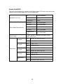
2000-Sheet Finisher D373
This finisher provides booklet as well as corner stapling. Equipped with two trays, the upper tray
holds stapled and shifted copies, and the lower tray holds booklet stapled and folded copies.
Dimensions w x d x h
657 x 613 x 960 mm (25.9 x 24.1 x 37.8")
Weight
Less than 63 kg (138.6 lb) (no punch unit)
Less than 65 kg (143 lb) (with punch unit)
Power Consumption
Less than 96 W
Noise
Less than 75 db
Configuration
Console type attached base-unit
Power Source
From base-unit
Proof Tray
Stack Capacity*
250 sheets A4, 8 1/2"x11" or smaller
50 sheets B4, 8 1/2"x14 or larger
Paper Size
A5-A3 SEF, A6 SEF, A6 LEF
5½" x8½" to11" x 17" SEF, 12"x18" SEF
Paper Weight
52 g/m²-163 g/m²
14 lb Bond- 43 lb Bond / 90 lb Index / 60 lb Cover
Stack Capacity*
Shift Tray
2,000
sheets
A4 LEF, 8 1/2"x11" LEF
1,000
sheets
A3 SEF, A4 SEF, B4 SEF, B5
11"x17" SEF, 8½" x14" SEF, 8½" x 11"
SEF,
12"x18" SEF
500
sheets
A5 LEF
100
sheets
A5 SEF, B6 SEF, A6 SEF, 5½" x8½"
SEF
Paper Size
A5 - A3 SEF, A6 SEF, B6 SEF
5½" x8½" to 11" x 17" SEF, 12" x 18" SEF
Paper Weight
52 g/m²-256 g/m²
14 lb Bond- 68 lb Bond / 140 lb Index / 90 lb Cover
Staple
Paper Size
B5-A3, 8 1/2"x11"-11"x17", 12"x18"
Paper Weight
64 g/m²-90 g/m², 17 lb Bond-28 lb Bond
Staple Position
Top, Bottom, 2 Staple, Top-slant
Staples Capacity*
Same Paper
50 sheets
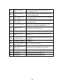
79
A4, 8½" x 11" or smaller
Size
30 sheets
B4, 8½" x 14" or larger
Mixed Paper
Size
30 sheets
A4 LEF & A3 SEF, B5 LEF & B4
SEF, 8½"x11" LEF & 11" x17" SEF
Booklet Stapling
15 sheets
A4 SEF, A3 SEF, B5 SEF, B4 SEF,
8 1/2"x11" SEF, 8 1/2"x14" SEF,
11"x17" SEF, 12"x18" SEF
Staple Replenishment
Corner staple
5,000 staples per cartridge
Booklet staple
2,000 staples per cartridge
A4 LEF, 8 1/2"x11" LEF
13-50 pages
2-12 pages
Same Size
A4 SEF, B5, 8 /12"x11" SEF
10-50 pages
2-9 pages
Corner
Staple
Capacity
10-30 pages
Others
2-9 pages
Mixed Size
Booklet
Staple
Capacity
A4 LEF + A3 SEF
B5 LEF + B4 SEF
8 1/2"x11" LEF + 11" x17"
SEF
A4 SEF, A3 SEF, B5 SEF, B4 SEF
8 1/2"x11" SEF, 8 1/2"x14" SEF, 11"x17" SEF
12"x18" SEF
2-30 pages
2-5 pages
6-10 pages
11-15 pages
80
D373/D374 Paper Specifications
Plain Paper
Paper Size
Paper Type
Copier
PPC
Used
Paper
Recycled
Paper
Colored
Paper
Translucent
Blueprint
A3 SEF
l
—
l
l
s
B4 SEF
l
s
l
l
s
A4 SEF
l
s
l
l
s
A4 LEF
'
s
'
'
s
B5 SEF
l
s
l
l
s
B5 LEF
'
s
'
'
s
A5 SEF
m
—
—
—
—
A5 LEF
m
—
—
—
—
B6 SEF
s
—
—
—
—
B6 LEF
s
—
—
—
—
12" x 18" SEF
l
—
l
l
—
11" x 17" SEF
l
—
l
l
s
8½" x 14"
l
—
l
l
s
8½" x 11" SEF
l
—
l
l
s
8½" x 11" LEF
'
—
'
'
s
5½" x 8½"
m
—
—
m
—
5½" x 8½"
m
—
—
m
—
81
'
Corner stapling, Shift, YES
l
Booklet stapling/folding, Shift,
YES
m
Shift ONLY
s
Shift NO
—
Not available
82
3000-Sheet Finisher D374
This finisher provides corner stapling only.
Finisher
Dimension (w x d x h)
657 x 613 x 960 mm
Weight
Less than 54 kg
Less than 56 kg with Punch Unit
Power Consumption
Less than 96 W
Noise
Less than 75 db
Configuration
Console type attached base-unit
Power Source
From base-unit
Proof Tray
Stack Capacity*
250 sheets A4, 8 1/2"x11" or smaller
50 sheets B4, 8 1/2"x14 or larger
Paper Size
A5-A3 SEF, A6 SEF, A6 SEF
5 1/2"x8 1/2"-11"x17"SEF, 12"x18" SEF
Paper Weight
52 g/m²-163 g/m²
14 lb Bond- 43 lb Bond / 90 lb Index / 60 lb Cover
3,000 sheets
A4 LEF, ½" x11" LEF "
1,500 sheets
A3 SEF, A4 SEF, B4 SEF, B5,
11"x17" SEF, 8½" x14" SEF, 8½" x
11" SEF, 12"x18" SEF
500 sheets
A5 LEF**
100 sheets
A5 SEF, B6 SEF, A6 SEF,
5½" x 8½",SEF
Stack Capacity*
Shift Tray
Paper Size
A5 - A3 SEF, A6 SEF, B6 SEF, 5½" x 8½"- 11"x17"
SEF, 12" x 18" SEF
Paper Weight
52 g/m²-256 g/m²
14 lb Bond- 68 lb Bond / 140 lb Index / 90 lb Cover
Staples
Paper Size
B5-A3
8 1/2"x11"-11"x17", 12"x18"
Paper Weight
64 g/m²-90 g/m²
17 lb Bond-28 lb Bond
Staple Position
Top, Bottom, 2 Staple, Top-slant
Stapling
Same Paper
50 sheets
83
A4, ½" x11" or smaller
Capacity
Size
30 sheets
B4, ½" x14" or larger
Mixed Paper
Size
30 sheets
A4 LEF + A3 SEF,
B5 LEF + B4 SEF,
8½" x11" LEF + 11" x17" SEF
Staple Replenishment
Cartridge exchange / 5000 pins per cartridge
Paper Size
A4 LEF, 8 1/2"x11" LEF
Stapled Stack Capacity
(same size)
A4 SEF, B5, 8 /12"x11"
SEF
Others
Stapled Stack Capacity
(mixed sizes)
A4 LEF & A3 SEF, B5 LEF
& B4 SEF, 8 1/2"x11" LEF
& 11" x17" SEF
84
Pages/Set
Sets
20-50 pages
150-60 sets
2-19 pages
150 sets
15-50 pages
100-30 sets
2-14 pages
100 sets
15-30 pages
100-33 sets
2-14 pages
100 sets
2-30 pages
50 set
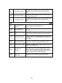
Punch Unit B702
This punch unit is designed for use with the 2000-Sheet Stapler D373 (both corner and booklet
stapling) and 3000-Sheet Stapler D374 (corner stapling only).
Available Punch Units
Punch Waste Replenishment
2/3 hole switchable
EU
2/4 holes switchable
Scandinavia
4 holes
NA 2-hole
Up to 5,000 sheets
NA 3-hole
Up to 5,000 sheets
EU 2-hole
Up to 14,000 sheets
EU 4-hole
Up to 7,000 sheets
Scandinavia 4hole
Up to 7,000 sheets
52 g/m²-163 g/m², 14 lb Bond –43 lb Bond / 90 lb
Index / 60 lb Cover
Paper Weight
NA 2-hole
NA 3-hole
Paper Sizes
NA
EU 2-hole
EU 4-hole
Scandinavia 4hole
SEF
A5 to A3, 5½" x 8½" to 11"x17"
LEF
A5 - A4, 5½" x 8½", 8½" x 11"
SEF
A3, B4, 11"x17"
LEF
A4, B5, 8½" x 11"
SEF
A5 - A3, 5½" x 8½" to 11" x 17"
LEF
A5 to A4, 5½" x 8½", 8½" x 11"
SEF
A3, B4, 11"x17"
LEF
A4, B5, 8½" x 11"
SEF
A5 to A3, 5½" x 8½" to 11" x 17"
LEF
A5 - A4, 5½" x8½", 8½" x 11"
85
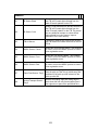
Z-Folding Unit ZF4000 B660
Paper Size
No Folding (52-300 g/m 2)
A3, A4, A5, A6 SEF, B4, B5, B6 SEF
11" x 17", 81/2"x14", 81/2"x11" SEF, 51/2"x81/2", 12" x
18"
Folding (64-80 g/m 2)
A3, B4, A4 SEF
11" x 17", 81/2"x14", 81/2"x11" SEF, 12" x 18"
Dimensions (w x d x h)
177 x 620 x 960 mm
7 x 24.5 x 37.8 in.
Weight
Less than 55 kg (121 lb)
Power Consumption
100 W max.
Power Supply
North America
120 V, 60 Hz, 1A
Europe/Asia
220-240 V, 50/60 Hz, 0.5A
A3/11" x 17" Tray B331
This option is installed in Tray 1 (tandem tray) of the copier so that Tray 1 can feed larger paper.
Tray 1 normally feeds LT or A4 only.
Dimension (w x d x h)
495 x 215 x 535 mm (19.5 x 8.5 x 21.1 in.)
Weight
11 kg (24.2 lb)
Paper Size
A3 SEF, B4 SEF, A4
11"x17" SEF, 8½" x 14" SEF, 8½" x 11"
Paper Capacity
1,000 Sheets
86
Copy Tray B476
The copy tray is installed receive copies when the copier is used without a finisher.
Dimension (w x d x h)
400 x 335 x 70 mm (15.8 x 13.2 x 2.8 in.)
Weight
640 g (1.4 lb)
Paper Capacity
500 Sheets
A4, 8½" x 11"
250 Sheets
A3, 11"x 17"
87
Machine Configuration
Configuration 1 (with D373/D374 Finisher)
No. Item
Comments
D014/D015a/b
Main unit
Tandem Tray
Built into main unit
A3/11"x17" Tray Type (B331)
Option for tandem tray
Tab Sheet Holder Type (B499)
Option for tandem tray
Copy Tray (B756)
For no finishers
Key Counter Bracket (B452)
Counter option
Key Counter Interface Unit Type (A) (B870)
Board required for key
counter
Card Reader Bracket (B498)
Counter option
LCT 4000 (D350) *1
Only one of these options
can be installed.
A4/LT LCT (B473)
88
No. Item
Comments
LCT Adapter (B699)
Required for LCT B473
LG Unit for A4/LT LCT (B474)
Option for LCT B473
Z-Folding Unit ZF4000 (B660) *1
Cover Interposer Tray (B704)
For D373 (2000-sheet),
D374 (3000-sheet) finishers
only. Only 1 tray. Cannot be
installed with Mail Box
(B762).
Finisher SR4020 (D373) *1
2000-sheet finisher, 50
staple, Booklet folding and
stapling
Finisher SR4010 (D374) *1
3000-sheet finisher, 50
staple, corner stapling only
Punch Unit (B702)
For either finisher D373 or
D374
Output Jogger Unit (B703)
For either finisher D373 or
D374
Mail Box CS391 (B762)
For D373 (2000-sheet),
D374 (3000-sheet finishers
only). Cannot be installed
with Cover Interposer Tray
(B704)
*1 New options for this machine.
89
Configuration 2 (with B830 Finisher)
No. Item
Comments
D014/D015a/b
Main unit
Tandem Tray
Built into main unit
A3/11"x17" Tray Type (B331)
Option for tandem tray
Tab Sheet Holder Type (B499)
Option for tandem tray
Copy Tray (B756)
For no finishers
Key Counter Bracket (B452)
Counter option
Key Counter Interface Unit Type A
(B870)
Board
Card Reader Bracket (B498)
Counter option
LCT 4000 (D350
Only one can be installed.
A4/LT LCT (B473)
LCT Adapter (B699)
Required for LCT B473 to adjust height.
LG Unit for A4/LT LCT (B474)
Option for LCT B473
Cover Interposer Tray CI 5000 (B835) Two source trays. Can be installed with
90
No. Item
Comments
3000-sheet finisher B830 only.
Z-Folding Unit ZF4000 (B660)
Can be installed with D373, D374, B830
finishers.
Finisher SR5000 (B830)
3000-Sheet finisher, 100 staples, jogger
standard.
Finisher Adapter (D375)
For Finisher B830
Punch Unit PU 5000 (B831)
For 3000-sheet finisher B830 only.
91
Electrical Components
Copier
No.
Component
Function
COUNTERS
TC1
Total Counter: FC
The mechanical counter for full color printing.
TC2
Total Counter: K
The mechanical counter for black-and-white printing.
HEATERS
H1
Lower Tray Heater
Keeps paper dry. Provided with machine, connection is
optional.
H2
Anti-condensation
Heater – Scanner
(Option)
Prevents the formation of condensation in the scanner
unit.
H3
Anti-condensation
Heater – Transfer
This options removes moisture from the air around the
paper transfer unit.
H4
Upper Tray Heater
Keeps paper dry. Provided with machine, connection is
optional.
HARD DISKS
The HDDs hold temporary files spooled for processing
and also store permanent files for the document server
application.
HDD1
HDD2
Hard Disk Drives
2nd HDD in a set of 4.
HDD3
3rd HDD in a set of 4.
HDD4
4th HDD in a set of 4.
92
LAMPS
L1
Exposure Lamp
Projects high intensity light on the original for exposure.
L2
Heating Roller Fusing
Lamp 1
590W fusing lamp in the heating roller.
L3
Heating Roller Fusing
Lamp 2
590W fusing lamp in the heating roller.
L4
Hot Roller Fusing
Lamp
350W fusing lamp inside the hot roller.
L5
Pressure Roller
Fusing Lamp
350W fusing lamp inside the pressure roller.
MOTORS
M1
Scanner Motor
Drives the scanner unit
M2
Lower Relay Motor
Drives the lower relay roller of the relay unit at the
vertical transport section.
M3
Paper Feed Motor:
Tray 1
Drives the paper feed roller and grip roller of tray 1
(tandem tray).
M4
Paper Feed Motor:
Tray 3
Drives the paper feed roller and grip roller of tray 3
(bottom tray).
M5
Paper Feed Motor:
Tray 2
Drives the paper feed roller and grip roller of tray 2
(middle tray).
M6
Waste Toner
Distribution Motor
Drives the coil that spans the top of the waste toner
bottle.
M7
Lift Motor - Tray 2
Switches on and drives a shaft and coupling that raises
a lift arm against the bottom plate under the paper
stack in tray 2
M8
Lift Motor: Tray 3
Drives a shaft and coupling that raises a lift arm against
the bottom plate under the paper stack in tray 3.
M9
Lift Motor: Tray 1
Drives pulleys and cables that lift the bottom plate of
tray 1 (tandem tray) until the top of the paper stack
reaches the correct height for feeding.
M10
Rear Fence Motor Tray 1
Switches on when the right paper tray sensor of the
tandem paper tray unit detects paper out and the left
paper tray sensor detects paper present.
M11
ITB Lift Motor
Rotates the cam that raises and lowers the ITB belt.
M12
Ozone Fan Motor
Draws air from around the drums and through the
ozone filter.
93
M13
Fusing Fan Motor
Cools the fusing unit.
M14
Fusing Cooling Fan
Motor
Draws cool air into the fusing unit through a vent and
past a heat sink mounted above the fusing unit.
M15
Fusing Exhaust Fan
Motor
Draws the hot air away from the heat sink mounted
above the fusing unit and expels the hot air through a
vent
M16
Fusing/Exit Motor
Drives the fusing unit and paper exit.
M17
PTR Motor
Drives the paper transfer roller (PTR).
M18
Bypass Feed Motor
Drives the upper relay roller that feeds each sheet to
the registration roller.
M19
Duplex Jogger Motor
Moves the jogger fences in the duplex unit.
M20
Duplex Unit Fan Motor
Cools the duplex unit.
M21
Duplex Transport Motor Drives transport rollers 3, 4 in the duplex unit.
M22
Duplex Inverter Motor
Feeds paper to the jogger section.
M23
Registration Motor
Rotates the registration roller.
94
M24
Image Transfer Fan
Motor
Cools the upper area of the transfer unit where the
PCUs contact the ITB.
M25
Pipe Cooling Fan
Motor
Pulls in air draws it over the fins attached to the front
end of the heat pipe roller.
M26
Paper Transport Fan
Motor - Rear
1 of 2 vacuum fans that produce suction to kepp paper
on the transport belt.
M27
Paper Transport Fan
Motor - Front
1 of 2 vacuum fans that produce suction to kepp paper
on the transport belt.
M28
Paper Exit Fan Motor
Draws hot air from around the paper exit area and
expels it from the left side of the machine.
M29
Front Duplex Fan
Motor
Draws hot air out of the duplex unit.
M30
Rear Duplex Fan Motor Draws hot air out of the duplex unit.
M31
ID Sensor Dust Fan
Motor
Blows air around the ID sensors to prevent dust from
collecting.
M32
Cooling Fan Motor
Draws air and sends it through a duct to the four PCU
cooling fans.
M33
Circulation Fan Motor
Circulates air.
M34
Laser Unit Cooling Fan
Motor - Front
Draws cool air into the machine.
M35
Laser Unit Cooing Fan
Motor - Rear
Expels hot air from the machine on the left side.
M36
PCU Motor : M
Drives all the rollers in the Magenta PCU.
M37
PCU Motor: K
Drives all the rollers in the Black PCU.
M38
PCU Motor: Y
Drives all the rollers in the Yellow PCU.
95
M39
PCU Motor: C
Drives all the rollers in the Cyan PCU.
M40
Controller Box Exhaust
Fan Motor 2
1 of 2 fans that cool the printed circuit boards at the
back of the machine.
M41
Controller Box Exhaust
Fan Motor 1
1 of 2 fans that cool the printed circuit boards at the
back of the machine.
M42
Drum Motor: Y
Drives the drum in the Yellow PCU.
M43
Drum Motor: C
Drives the drum in the Cyan PCU.
M44
Drum Motor: M
Drives the drum in the Magenta PCU.
M45
Drum Motor: K
Drives the drum in the Black PCU.
M46
ITB Drive Motor
Rotates the image transfer roller that drives the ITB.
M47
3rd Mirror Motor - M
Fine adjusts the position of the 3rd mirror of the optics
for M (magenta) during MUSIC adjustment.
M48
Polygon Mirror Motor
Rotates the polygon mirror in the laser optics unit
M49
3rd Mirror Motor - Y
Fine adjusts the position of the 3rd mirror of the optics
for Y (Yellow) during MUSIC adjustment.
M50
3rd Mirror Motor - C
Fine adjusts the position of the 3rd mirror of the optics
for C (Cyan) during MUSIC adjustment.
M51
Toner Hopper Motor
Drives the toner pump clutch and sub hopper clutch of
each PCU.
M52
PCU Fan Motor: Y
Cools the Yellow PCU.
M53
PCU Fan Motor: C
Cools the Cyan PCU.
M54
PCU Fan Motor: M
Cools the Magenta PCU
96
M55
Scanner Unit Fan
Motor - Rear Left
Cools the left, rear corner of the SIOB.
M56
Scanner Unit Fan
Motor - Rear Center
Cools the rear, center area of the SIOB.
M57
Scanner Unit Fan
Motor - Right
Exhausts warm air from the SIOB area.
M58
Waste Toner Collection
Bottle Motor
Drives the waste toner bottle transport coil that moves
the toner from the central collection point into the waste
toner bottle.
MECHANICAL CLUTCHES
MC1
Bypass Feed Clutch
Engages and operates the pick-up roller at the bypass
feed tray.
MC2
Toner Pump Clutch: M
Engages the and drives the Magenta toner pump to
pull toner from the Magenta STC.
MC3
Engages the toner supply coils in the sub hopper of the
Toner Supply Clutch: M Magenta PCU to send toner to the development unit
below.
MC4
Toner Pump Clutch : K
MC5
Engages the toner supply coils in the sub hopper of the
Toner Supply Clutch : K Black PCU to send toner to the development unit
below.
MC6
Toner Pump Clutch: Y
Engages the and drives the Black toner pump to pull
toner from the Black STC.
Engages the drive shaft and rotor of the Yellow toner
pump to pull toner from the Yellow STC when more
toner is needed.
97
MC7
Toner Supply Clutch: Y
Engages the toner supply coils in the sub hopper of the
Yellow PCU to send toner to the development unit
below.
MC8
Toner Pump Clutch: C
Engages the and drives the Cyan toner pump to pull
toner from the Cyan STC.
MC9
Toner Supply Clutch: C
Engages the toner supply coils in the sub hopper of the
Cyan PCU to send toner to the development unit
below.
PCBs
PCB1
PFB (Paper Feed
Board)
Controls paper trays and paper feed.
PCB2
AC Drive Board
Controls the power supply to the fusing lamps, heaters,
and PSU.
PCB3
PSU (Power Supply
Unit)
Supplies DC current to the machine and contains the
AC drive that controls the fusing lamp power supply.
PCB4
DRB (Drive Board)
Contains the circuits for the stepping motors that drive
the printer engine, and distributes electrical power to all
other PCBs.
PCB5
Power Pack:
Development Bias
Supplies the voltage for the bias applied to the
developer in the PCUs by the development rollers.
PCB6
Power Pack: Charge
Supplies the voltage for the charge applied to the OPC
drums by the charge roller.
PCB7
Power Pack:
Transfer
Supplies charge to 1) the four image transfer rollers
that pull the toner images from the four from the four
drums (Y, M, C, K), and 2) to the paper transfer roller
that pulls the image off the ITB onto paper.
PCB8
Power Pack Separation
Supplies the dc/ac charges for paper separation.
98
PCB9
DTMB
(Drum/Transfer
Motor Board)
Controls the motors that drive the OPC drums and ITB.
PCB10
IPU
Performs: 1) Image processing control, 2) GW
controller interface, 3) peripheral timing control.
PCB11
Potential Sensor
Board
Processes data from the Y, M, C, K, potential sensors.
PCB12
CNB (Connector
Board)
Sorts and routes signals to electrical components.
PCB13
IDCB: C1
One of two ID control boards at the base of the Cyan
STC. The CPU reads the board to confirm that the
correct STC is inserted into the correct bin.
PCB14
IDCB: M1
One of two ID control boards at the base of the
Magenta STC. The CPU reads the board to confirm
that the correct STC is inserted into the correct bin.
PCB15
IDCB: K1
One of two ID control boards at the base of the Black
STC. The CPU reads the board to confirm that the
correct STC is inserted into the correct bin.
PCB16
IDCB: Y1
One of two ID control boards at the base of the Yellow
STC. The CPU reads the board to confirm that the
correct STC is inserted into the correct bin.
PCB17
SBU (Sensor Board
Unit)
Contains the CCD. Converts CCD analog signals to
digital signals.
PCB18
SIOB (Scanner
Interface Board)
Controls all the sensors in the scanner unit and
controls the carriage drive stepping motors.
PCB19
Lamp Regulator
Converts the dc power input to a stable, high frequency
ac output to the exposure lamp.
99
VBCU
VBCU: 1) Engine sequence control (all sensors,
motors, fusing temperature monitoring circuits), 2)
Scanning control, 3) Exposure control, 3) Image
processing control, 4) GW controller I/F, 5) Peripheral
timing control.
The I/O control board controls 1) Input/output ports for
all sensors, motor, solenoids, 2) drivers, 3) high voltage
power supply for PWM, and 4) analog input signals.
LD 1 (2/2)
Laser Diode 1, 2nd of a pair, 1 of 8.
LD 1 (1/2)
Laser Diode 1, 1st of a pair, 1 of 8.
LD 2 (2/2)
Laser Diode 2, 2nd of a pair, 1 of 8.
LD 2 (1/2)
Laser Diode 2, 1st of a pair, 1 of 8.
LD 3 (2/2)
Laser Diode 3, 2nd of a pair, 1 of 8.
LD 3 (1/2)
Laser Diode 3, 1st of a pair, 1 of 8.
LD 4 (2/2)
Laser Diode 4, 2nd of a pair, 1 of 8.
LD 4 (1/2)
Laser Diode 4, 1st of a pair, 1 of 8.
PCB25
LSDB: K Front
Front Laser Synchronization Detector Board for Laser
Diode 4.
PCB26
LSDB: M Front
Front Laser Synchronization Detector Board for Laser
Diode 3.
PCB27
LSDB: C Front
Front Laser Synchronization Detector Board for Laser
Diode 2.
PCB28
LSDB: Y Front
Front Laser Synchronization Detector Board for Laser
Diode 1.
PCB20
PCB21
PCB22
PCB23
PCB24
100
PCB29
LSDB: Y Rear
Rear Laser Synchronization Detector Board for Laser
Diode 1.
PCB30
LSDB: C Rear
Rear Laser Synchronization Detector Board for Laser
Diode 2.
PCB31
LSDB: M Rear
Rear Laser Synchronization Detector Board for Laser
Diode 3.
PCB32
LSDB: K Rear
Rear Laser Synchronization Detector Board for Laser
Diode 4.
PCB33
Controller Board
Incorporates the GW architecture, and connects to the
BICU and PCI I/F. All the options for the printer are
controlled by this board.
PCB34
Mother Board
Interfaces the controller and the BICU.
PCB35
RAPI EXT Board
Interface the copy connector and EFI controller.
PCB36
OPU (Operation
Panel Unit)
Controls the operation panel.
PCB37
PI Board
Interfaces the IPU and RDS.
QUENCHING LAMPS
QL1
Quenching Lamp : K
Eliminates electrical charge and neutralizes the
surface of the drum in the Black PCU.
QL2
Quenching Lamp: C
Eliminates electrical charge and neutralizes the
surface of the drum in the Cyan PCU.
QL3
Quenching Lamp: M
Eliminates electrical charge and neutralizes the
surface of the drum in the Magenta PCU.
QL4
Quenching Lamp: Y
Eliminates electrical charge and neutralizes the
surface of the drum in the Yellow PCU.
101
SENSORS
ID Sensor: Black
Reads 1) light reflected from the bare surface of
the ITB, and 2) reads light reflected from the
black ID sensor patterns on the ITB.
S2
ID Sensor: Color
Reads 1) light reflected from the bare surface of
the ITB, and 2) reads light reflected from the
color ID sensor patterns on the ITB. This sensor
has one additional receptor to collect diffuse
light reflected from color toner to improve
calculation of the toner density.
S3
ITB Lift Sensor
This sensor switches the ITB lift motor off when
the ITB comes into contact the drums of the four
PCUs.
S4
MUSIC Sensor: Center
Reads the center MUSIC pattern. This feedback
is used to control the MUSIC process to correct
color registration errors.
S5
MUSIC Sensor: Front
Reads the front MUSIC pattern. This feedback
is used to control the MUSIC process to correct
color registration errors.
S6
MUSIC Sensor: Rear
Reads the Rear MUSIC pattern. This feedback
is used to control the MUSIC process to correct
color registration errors.
S7
Paper Feed Sensor: Tray 2
Detects the leading edge of each sheet of paper
from the pick–up roller of tray (middle tray) and
switches off the pick–up roller solenoid so the
pick–up roller lifts.
S8
Vertical Transport Sensor:
Tray 2
Detects the leading edge and trailing edge of
each sheet fed from tray 2 and signals a jam if
the edges do not pass at the prescribed time.
S1
102
Paper End Sensor: Tray 2
Receives light reflected from the paper until the
last sheet is fed from tray 2 (middle tray), then
signals paper end.
Lift Sensor: Tray 2
Detects when the pick–up roller (pushed up by
the top of the paper stack in the right side of the
tandem tray) has reached the correct height for
paper feed and then switches off the tray 2
(middle tray) lift motor.
S11
Paper Feed Sensor: Tray 3
Detects the leading edge of each sheet of paper
from the pick–up roller of tray 3 (bottom tray)
and switches off the pick–up roller solenoid so
the pick–up roller lifts.
S12
Vertical Transport Sensor:
Tray 3
Detects the leading edge and trailing edge of
each sheet fed from tray 3 and signals a jam if
the edges do not pass at the prescribed time.
S13
Paper End Sensor: Tray 3
Receives light reflected from the paper until the
last sheet is fed from tray 3 (bottom tray), then
signals paper end.
Lift Sensor: Tray 3
Detects when the pick–up roller (pushed up by
the top of the paper stack in the right side of the
tandem tray) has reached the correct height for
paper feed and then switches off the tray 3
(bottom tray) lift motor.
Bottom
Temperature/Humidity
Sensor
Near the waste toner bottle. Detects ambient
temperature and humidity and then this output is
used to control the amount of current applied to
the paper transfer roller and ITB when the
image is transferred to paper. Also used to
correct the fusing temperature, and to extend
the fusing unit idle time at low room
temperatures.
S9
S10
S14
S15
103
S16
Waste Toner Bottle Set
Sensor
Detects the position of the waste toner bottle
and confirms whether it is set correctly.
S17
Waste Toner Bottle NearFull Sensor
When the level of the waste toner rises high
enough to move the actuator of this sensor out
of its normal position, the sensor signals the
machine that the waste toner bottle is nearly full.
S18
Waste Toner Bottle Full
Sensor
Signals an alert when the waste toner bottle is
full.
S19
Detects the leading edge of each sheet of paper
from the pick–up roller of tray 1 (tandem tray)
Paper Feed Sensor - Tray 1
and switches off the pick–up roller solenoid so
the pick–up roller lifts.
S20
Vertical Transport Sensor Tray 1
Detects the leading edge and trailing edge of
each sheet fed from tray 1, 2, and 3 and signals
a jam if the edges do not pass at the prescribed
time.
S21
Paper End Sensor - Tray 1
Detects when the last sheet is fed from tray 1.
S22
Lift Sensor - Tray 1
Detects when the pick–up roller (pushed up by
the top of the paper stack in the right side of the
tandem tray) has reached the correct height for
paper feed and then switches off the tray 1
(tandem tray) lift motor.
S23
Paper Near End Sensor Tray 2
Detects the near end condition for tray 2 (middle
tray, a universal cassette).
S24
Paper Near End Sensor:
Tray 3
Detects the near end condition for tray 3 (middle
tray, a universal cassette).
S25
Front Side Fence Open
Sensor
Detects the actuator on the front side fence after
it has reached the open position in the tandem
tray.
S26
Front Side Fence Closed
Sensor
Detects the actuator on the front side fence after
it has reached the closed position in the tandem
tray.
S27
Rear Side Fence Open
Sensor
Detects the actuator on the rear side fence after
it has reached the open position in the tandem
tray.
S28
Rear Side Fence Closed
Sensor
Detects the actuator on the rear side fence after
it has reached the closed position in the tandem
tray.
S29
Right Tray Down Sensor
Detects the bottom plate of the right tray and
switches off the tray 1 lift motor and stops the
bottom plate.
104
Paper Near End Sensor Tray 1
Signals 10% paper remaining when the actuator
on the right rail of the right tray in the tandem
tray passes.
S31
Paper Height Sensor
Signals 100% paper remaining until activated.
Signals 50% paper remaining when the actuator
on the left rail of the right tray in the tandem tray
passes.
S32
Paper Height Sensor
Signals 30% paper remaining when the actuator
on the left rail of the right tray in the tandem tray
passes.
S33
Paper Height Sensor
When near end sensor 1 on right rail of the right
tray of the tandem tray is actuated, and paper
height sensor 3 has detected the passing of the
actuator on the left rail, then the near end
sensor signals 10% paper remaining.
S34
Right Tray Paper Sensor
Detects paper in the right side of the tandem
paper tray.
S30
105
S35
Rear Fence HP Sensor
Detects the actuator on the rear fence in the
tandem tray and switches off the rear fence
motor.
S36
Rear Fence Return Sensor
Detects the actuator on the rear fence in the
tandem tray and reverses the rear fence motor.
S37
Left Tray Paper Sensor
Detects the presence of paper in the left tray of
the tandem tray.
S38
Monitors the surface temperature of the heating
Heating Roller Temperature
roller and breaks the circuits to the fusing lamps
Sensor
if the heating roller overheats.
S39
Waste Toner Lock Sensor
Signals an alert if the waste toner collection coil
locks and stops rotating.
Duplex Transport Sensor 1
The feeler of this sensor detects the leading
edge and trailing edge of each sheet as it
passes from the jogger unit above and into the
horizontal feed path of the duplex unit below.
Signals a jam if the paper does not arrive at or
reach the sensor location at the prescribed time.
S41
Duplex Inverter Sensor
Detects the leading edge of the paper at the
inverter exit roller and signals to switch off the
reverse trigger roller solenoid to signal a jam if
the paper does not arrive at the prescribed time.
S42
Duplex Entrance Sensor
Detects paper jams at the entrance of the
duplex unit.
Duplex Transport Sensor 3
Detects the leading edge and trailing edge of
each sheet as it passes from the jogger unit
above through the horizontal feed path of the
duplex unit below. Signals a jam if the paper
does not arrive at or reach the sensor location at
the prescribed time.
Duplex Transport Sensor 2
Detects the leading edge and trailing edge of
each sheet as it passes from the jogger unit
above and into the horizontal feed path of the
duplex unit below. Signals a jam if the paper
does not arrive at or reach the sensor location at
the prescribed time.
S45
Duplex Jogger HP Sensor
At power on, detects the actuators on the jogger
fences of the duplex unit, switches off the jogger
motor and stops the fences at their home
positions.
S46
Double-Feed Detection
Sensor
Receives the light emitted from the double–feed
detection LED and reflected from the surface of
each sheet in the paper path. Signals an error if
S40
S43
S44
106
the thickness of the paper is not the same as
the previous sheet.
S47
Guide Plate Position
Sensor
S48
Relay Sensor
Detects jams at the top of the vertical paper
path.
S49
Registration Sensor
Detects the leading edge of the paper and
switches off the registration motor and stops the
registration roller briefly but long enough to
correct buckle the paper.
S50
Paper Exit Sensor
Detects the leading and trailing edge of each
sheet at the paper exit slot to check timing and
detect jams.
S51
Bypass Paper Sensor
Detects the presence of paper in the bypass
tray.
S52
Bypass Paper End Sensor
Signals paper out when the last sheet feeds
from the bypass tray.
107
S53
Bypass Paper Size Sensor
Reads the positions of the side fences
(manually adjusted) to detect the width of the
paper in the bypass tray. (Paper length is read
with pulse counts from the registration sensor.)
S54
Paper Exit Relay Sensor
Detects paper jams at the paper exit if the paper
does not arrive or leave the machine at the
prescribed time.
S55
Copy Tray Full Sensor
(Option)
Detects when the Copy Paper Tray B75 is full
and temporarily pauses printing so the operator
can remove the stack from the tray and
continue.
S56
TD Sensor: M
Monitors the amount of toner in the
developer/toner mixture in the development unit
of the Magenta PCU.
S57
TD Sensor : K
Monitors the amount of toner in the
developer/toner mixture in the development unit
of the Black PCU.
S58
Temperature/Humidity
Sensor : PCU K
The temperature and humidity readings of this
sensor are referenced to a lookup table stored
in the ROM to 1) Correct the charge roller
voltage , and 2) Set the length of time the
agitators in the development unit rotate to mix
the toner and developer.
S59
TD Sensor: Y
Monitors the amount of toner in the
developer/toner mixture in the development unit
of the Yellow PCU.
S60
TD Sensor: C
Monitors the amount of toner in the
developer/toner mixture in the development unit
of the Cyan PCU.
108
S61
ITB Position Sensor 2
Reads the encoder film strip on the front edge of
the ITB and sends the sub scan scale signal to
the CPU.
S62
ITB Position Sensor 1
Reads the encoder film strip on the front edge of
the ITB and sends the main scan scale signal to
the CPU.
S63
Potential Sensor : K
Reads the potential sensor pattern from the
surface of the drum in the black PCU.
S64
Potential Sensor: M
Reads the potential sensor pattern from the
surface of the drum in the magenta PCU.
S65
Potential Sensor: C
Reads the potential sensor pattern from the
surface of the drum in the cyan PCU.
S66
Potential Sensor: Y
Reads the potential sensor pattern from the
surface of the drum in the yellow PCU.
S67
Temperature Sensor:
Optics 1
1 of 2 sensors (located near the left f-theta lens)
that monitors the temperature in the optics unit.
The results are used in the MUSIC process.
S68
Temperature Sensor:
Optics 2
1 of 2 sensors (located near the right f-theta
lens) that monitors the temperature in the optics
unit. The results are used in the MUSIC
process.
S69
Toner End Sensor: M
Detects toner end for magenta toner.
S70
Toner End Sensor : K
Detects toner end for black toner.
S71
Toner End Sensor: Y
Detects toner end for yellow toner.
S72
Toner End Sensor: C
Detects toner end for cyan toner.
S73
Scanner HP Sensor
Detects the home position of the scanner.
109
Original Width Sensors
APS1 (a board) holds two original width sensors
under the exposure glass. The detection
combinations of these sensors determine the
width of the original on the exposure glass
positioned for LEF.
Original Length Sensors - 1
APS2 (a board) holds two original length
sensors under the exposure glass. The
detection combinations of these sensors
determine the length of the original on the
exposure glass positioned for SEF.
S76
Original Length Sensor -2
APS3 (a board) holds one original length sensor
under the exposure glass. The detection
combination of this sensor and other sensors
determine the length of the original on the
exposure glass positioned for SEF.
S77
Accordion Jam Sensor
Detects jams at the fusing exit by confirming
that paper arrives at the prescribed time.
S78
Fusing Exit Sensor
Detects jams at the fusing exit by confirming
that paper leaves at the prescribed time.
S79
LCT Relay Sensor
Confirms whether the LCT is set correctly.
S74
S75
110
LEDs
LED1
Double-Feed Detection LED
Emits light which is reflected from the paper to
the double–feed detection sensor to test the
translucence of each sheet for double-feed
detection.
LED2
Accordion Jam Sensor (LED)
Flashes to show the user which lever to
release to remove a paper jam from the fusing
rollers.
LED3
Fusing Exit Sensor (LED)
Flashes to show the user which lever to
release to remove a paper jam from the fusing
unit.
SOLENOIDS
Pick–up Solenoid:
Tray 2
Switches on when the tray 2 (middle tray) lift motor
switches on. This solenoid lowers the pick–up roller of
tray 3.
SOL2
Separation Roller
Solenoid: Tray 2
When tray 2 (middle tray) is selected as the paper
source, this solenoid energizes and brings the
separation roller in contact with the feed roller until the
leading edge of the sheet feeds to the paper feed
sensor.
SOL3
Pick–up Solenoid:
Tray 3
Switches on when the tray 3 (bottom tray) lift motor
switches on. This solenoid lowers the pick–up roller of
tray 3.
SOL1
111
SOL4
Separation Roller
Solenoid: Tray 3
When tray 3 (bottom tray) is selected as the paper
source, this solenoid energizes and brings the
separation roller in contact with the feed roller until the
leading edge of the sheet feeds to the paper feed
sensor.
SOL5
Pick–up Solenoid Tray 1
Switches on when the tray 1 (tandem tray) lift motor
switches on. This solenoid lowers the pick–up roller of
tray 1.
Separation Roller
Solenoid - Tray 1
When tray 1 (tandem tray) is selected as the paper
source, this solenoid energizes and brings the
separation roller in contact with the feed roller until the
leading edge of the sheet feeds to the paper feed
sensor.
Front Side Fence
Solenoid -Tray 1
When the right tray paper sensor in the tandem tray
signals paper out, and the left tray paper sensor signals
paper present, this energizes this solenoid which pulls
open the front side fence until the front side fence open
sensor detects the actuator of the front side fence and
switches off the solenoid, leaving it locked in the open
position, to allow the rear fence to push the paper stack
from the left tray into the right tray.
Rear Side Fence
Solenoid - Tray 1
When the right tray paper sensor in the tandem tray
signals paper out, and the left tray paper sensor signals
paper present, this energizes this solenoid which pulls
open the rear side fence until the rear side fence open
sensor detects the actuator of the rear side fence and
switches off the solenoid, leaving it locked in the open
position, to allow rear fence to push the paper stack
from the left tray into the right tray.
SOL6
SOL7
SOL8
112
SOL9
Right Tray Lock
Solenoid - Tray 1
Releases the lock lever when the left tray paper sensor
in the tandem tray signals that there is no paper in the
left tray.
SOL10
Left Tray Lock
Solenoid - Tray 1
When the rear fence motor in the tandem tray switches
on, this energizes the left tray lock solenoid. This locks
the left tray so it does not move while the rear fence
pushes the stack from the left tray to the right tray.
SOL11
Duplex Junction
Gate Solenoid
Controls the opening and closing of the duplex junction
gate at the mouth of the inverter unit.
SOL12
Reverse Trigger
Roller Solenoid
After a sheet is detected by the duplex entrance sensor,
this solenoid energizes and pushes down the reverse
trigger roller.
SOL13
Guide Plate
Solenoid
Energizes when a jam occurs between the vertical
transport rollers and registration roller to force the guide
plate open and divert paper fed from below into the
duplex tray.
SOL14
Inverter Junction
Gate Solenoid
Operates the inverter junction gate. The inverter
injunction gate turns paper into the path to the inverter
unit below where it is 1) inverted for face–down output
or 2) inverted for 2nd side printing.
SOL15
Bypass Pick–up
Solenoid
Switches on and lowers the pick–up roller to the top of
the stack in the bypass tray
113
SWITCHES
SW1
Lower Front Door
Switch
Detects whether the front door is open or closed.
SW2
Main Power Switch
Switches the machine off and on.
SW3
Upper Front Door
Switches (x5)
Detect whether the front door is open or closed.
SW4
Paper Size Switch:
Tray 2
The switch detects the position of the dial (set
manually), and signals the paper size with a simple 5–
digit binary code.
SW5
Paper Size Switch:
Tray 3
The switch detects the position of the dial (set
manually), and signals the paper size with a simple 5–
digit binary code.
THERMISTORS
TH1
Heating Roller
Thermistor
Monitors the end of the heating roller and breaks the circuit
to the heating lamps if a lamp overheats.
TH2
Hot Roller
Thermistor
Detects and monitors the temperature of the hot roller for
fusing temperature control.
TH3
Pressure
Roller
Thermistor
Detects the temperature of the hot roller for fusing
temperature control.
114
THERMOSTATS
TS1
Pressure
Roller
Thermostat 1
Monitors the temperature of the pressure roller and cuts the
circuit if the pressure roller fusing lamp overheats.
TS2
Pressure
Roller
Thermostat 2
Monitors the temperature of the pressure roller and cuts the
circuit if the pressure roller fusing lamp overheats.
TS3
Thermostat 1
Monitors the temperature of the fusing belt nd cuts the circuit
if the fusing unit overheats.
TS4
Thermostat 2
Monitors the temperature of the fusing belt nd cuts the circuit
if the fusing unit overheats.
TS5
Thermostat 3
Monitors the temperature of the fusing belt nd cuts the circuit
if the fusing unit overheats.
TS6
Thermostat 4
Monitors the temperature of the fusing belt nd cuts the circuit
if the fusing unit overheats.
115
ARDF
No.
Component
Function
MOTORS
M1
Feed Motor
Drives the feed belt, and the separation, pick-up, and
transport as far as the 1st transport roller.
M2
Transport Motor
Controls the original scanning speed.
M3
Exit Motor
Feeds paper out of the ARDF and onto the original
exit table.
M4
Upper Inverter Motor
Controls the rotation of the upper inverter roller that
feeds the original in and out of the upper inverter
path.
M5
Lower Inverter Motor
Controls the rotation of the lower inverter roller that
feeds the original in and out of the lower inverter path.
M6
Pick-up Motor
Raises and lowers the pick-up roller.
M7
Bottom Plate Lift
Motor
Raises and lowers the bottom under the original
stack.
ARDF Main Board
Controls the ARDF and communicates with the main
copier boards.
PCB
PCB1
116
SENSORS
S1
Original Width Sensor
2
Detects paper wider than 191.5 mm (7.5 in.)
measured from the reference point.
S2
Original Width Sensor
3
Detects paper wider than 230 mm (9.1 in.) measured
from the reference point.
S3
Original Width Sensor
4
Detects paper wider than 263.5 mm (10.4 in.)
measured from the reference point.
S4
Original Width Sensor
5
Detects paper wider than 288 mm (11.3 in.) measured
from the reference point.
S5
Original Width Sensor
1
Detects paper wider than 138 mm (5.4 in.) measured
from the reference point.
S6
Original Set Sensor
Detects whether an original is on the table.
S7
Bottom Plate HP
Sensor
Detects whether the bottom plate is in the down
position or not.
S8
Feed Cover Sensor
Detects whether the feed cover is open or not.
S9
Bottom Plate Position
Sensor
Detects when the original is at the correct position for
feeding.
S10
Upper Inverter Sensor
Detects leading and trailing edge of the paper as it
enters and leaves the upper path of the inverter.
S11
LG Detection Sensor
Detects paper longer than 318 mm (12.5 in.) on the
original table.
S12
A4 Detection Sensor
Detects paper longer than 291 mm (11.5 in.) on the
original table.
S13
B5 Detection Sensor
Detects paper longer than 240 mm (9.5 in.) on the
original table.
117
Interval Sensor
Adjusts the timing of the original transport speed to
the original scanning speed after the original feeds.
During duplex scanning, or if original is small (B6, A5,
or HLT) the interval sensor detects the leading edge
of the original and delays the pre-scanning motor for
the prescribed number of pulses to buckle the original
and correct skew.
S15
Skew Correction
Sensor
After pick-up and separation, the skew correction
sensor detects the leading edge of the original. This
signal slows the rotation of the entrance roller for a
prescribed number of pulses to buckle the original
and correct skew.
S16
Separation Sensor
Detects the separation of the original.
S17
Exit Sensor
Detects the leading and trailing edges of paper feed
out to the original table and detects misfeeds. Also
signals when to stop the scanning belt.
S18
Registration Sensor
Detects the leading edge and trailing edges of the
original to detects jams and stops the original at the
ADF exposure glass to correct buckle.
S19
Pick-up Roller HP
Sensor
Detects whether the pick-up roller is up or not.
S20
Lower inverter sensor
Detects the original in the path of the lower inverter
before it feeds to the inverter rollers for 2nd side
scanning, or feeds to the exit rollers for exit.
S21
ARDF Position
Sensor
Detects whether the ARDF unit is up or down for
scanning on the main exposure glass (book mode).
S22
APS Start Sensor
Signals the CPU when the DF is opened and closed
(for platen mode) so that the original size sensors in
the copier can check the original size.
S14
118
SOLENOIDS
SOL1
SOL2
Upper Inverter
Solenoid
Opens and closes the upper junction gate at the
entrance of the upper inverter path. During simplex
scanning, closes the upper inverter path so the
original exits straight to the exit tray. During duplex
scanning, opens to allow the original to enter the
upper inverter path and closes to direct it once again
into the feed path for 2nd side scanning.
Lower Inverter
Solenoid
Opens and closes the lower junction gate. During
duplex scanning opens after the 2nd side is scanned
to direct the original into the lower inverter path while
the next sheet is fed to the upper inverter path above,
then closes to direct the original out onto the original
exit tray.
119
120
DETAILED DESCRIPTIONS
121
122
DETAILED DESCRIPTIONS
General Overview
Main Machine
123
124
1. Transport Belt (ARDF)
18. Grip Roller
2. Grip Roller (ARDF)
19. Feed Sensor (Paper Tray)
3. Feed Belt (ARDF)
20. Feed Roller (Paper Tray)
4. Separation Roller (ARDF)
21. Separation Roller (Paper Tray)
5. Pick-up Roller (ARDF)
22. Pick-up Roller (Paper Tray)
6. Upper Inverter Roller (ARDF)
23. Paper Size Switch (Tray 3)
7. Lower Inverter Roller (ARDF)
24. Universal Tray (Tray 3)
8. Development Roller
25. Universal Tray (Tray 2)
9. Charge Roller
26. Paper Size Switch (Tray 2)
10. Charge Corona Unit
27. Tandem Tray (Tray 1)
11. PCU
28. Inverter Exit Roller
12. OPC Drum
29. Inverter Entrance Roller
13. Image Transfer Roller
30. Pressure Roller
14. ITB Unit
31. Hot Roller
15. Transfer Belt
32. Exit Roller
16. Registration Roller
33. Heating Roller
17. PTR Roller
34. Exposure Glass (ARDF)
The color PCU units (Y,M,C) use a charge roller to charge the surface of the OPC drum. The
K PCU uses a charge corona unit (Scorotron type) to charge the surface of the drum.
125
Laser Unit
There is an LD unit for each color, and each LD unit uses a two-beam system. A photodiode
(PD) in each LD unit detects the light emitted from the LD unit. The output of the PD is fed
back to the LD control board. The LD control board uses this information to control the
amount of light to make sure that it remains at the correct level.
Dual Beam Writing
In each LD unit, two beams move across the drum in the main scan direction.
The use of two beams:
Makes the machine print faster.
Reduces the number of turns of the polygon mirror for a page to prolong the service life
of the motor.
Reduces the amount motor noise.
The beam pitch is fixed at 600 dpi and is not adjustable.
LD Safety Switches
To ensure the safety of customers and customer engineers, two switches inside the cover
prevent the laser beams from switching on accidentally. When the front cover is open, the
+5V line connecting each LD driver on the LD control board is disconnected.
126
127
Boards
Overview of Important Components
VBCU (Base Engine and Image Control Unit)
The VBCU is the main control board. It combines the functions of the BCU and IOB.
The VBCU controls these BCU (Base Control Unit) functions:
Engine sequence control (all sensors, motors, fusing temperature control circuits)
Image processing control (on the IPU)
Scanning control
GW controller interface
Peripheral timing control
The VBCU also controls these IOB (I/O Control Board) functions:
Input and output ports for all sensors, motors, solenoids
All drivers
High voltage power supply
Analog input signals. Converts analog data to 10-bit digital data. The CPU on the VBCU
reads this data.
Controller
The GW controller board controls all the optional applications. It contains the GW
architecture ASICs, and connects to the VBCU and PCI interface. The controller board also
has two SD card sockets. The SD card slots are use for:
Installing holding optional applications (Printer/Scanner, PostScript3 and other options)
Engine and operational panel firmware updates
Moving an application from one SD card to another with SP5873-1.
SBU (Sensor Board Unit)
The SBU:
Receives analog signals from the CCD and converts them to digital signals.
Sends serial data to the VBCU.
Sends signals from the main CPU to the SIOB, to control the scanner components.
Sends digital data to the IPU.
SIOB (Scanner I/O Board)
This board controls the scanner motor and all the sensors in the scanner unit. The CPU
controls this board.
128
LDB (Laser Diode Drive Board)
This board contains the driver for the laser diodes.
HDD (Hard Disk Drives)
This board stores all the temporary files for job processing and all permanent files for the
document server.
PSU (Power Supply Unit)
Supplies DC to the machine, and contains the AC supply that controls the power to the
fusing lamps.
IPU
SBU (Sensor Board Unit)
SBU
The SBU does the following functions:
Black level correction
White level correction
Color balance calibration
Creating the SBU test pattern
129
Operation Summary
The signals from the 3-line CCD, one line for each color (R, G, B) and 4 analog signals per
line (F_ODD, F_EVEN, L_ODD, L_EVEN), are sampled by the ASIC and converted to digital
signals in the 10-bit A/D converter. This is the first phase of processing the data scanned
from the original.
Lens Block Replacement
The controller stores the SBU settings. These values must be restored after the lens block is
replaced:
SP4008
Sub Scan Mag
Sub Scan Magnification Adjustment
SP4010
Sub Scan Reg
Sub Scan Registration Adjustment
SP4011
Main Scan Reg
Main Scan Registration Adjustment
Before lens block replacement, enter the SP mode and note the settings of SP4800 001
to 003 (ARDF density adjustments for R, G, B).
After lens block replacement, do some copy samples with the ARDF, then check the
copies.
If the copies have background, change SP4800 001 to 003 to their previous settings, or
adjust until the background is acceptable.
These SP codes are also used to adjust the ARDF scanning density, if the scanning
densities of the ARDF and the platen mode are not the same.
SBU Test Mode
3.
Use SP4907 (Set SBU Test Pattern) to select the pattern to print.
4.
Touch "Copy Window" then press the Start key twice.
130
IPU (Image Processing Unit)
The IPU does the following:
Controls the scanner
Processes the image signals from the SBU and sends them over the PCI bus to the
controller memory
Receives the image processing signals sent over the PCI bus from the controller
memory, processes them, then outputs them to the VGAVD.
Outputs the control signals for the ARDF
Controls the relay of power and signals
Image processing, ADS correction, and line width correction are done on the VBCU board for
all the digital data sent from the SBU. Finally, the processed data is sent to the printer as
digital signals (2 bits/pixel).
131
Copy Process Overview
Raising and Lowering of the ITB Unit
This machine has four PCUs arranged in a straight line: Y, C, M, K above the ITB (Image
Transfer Belt) unit [A]:
The ITB lift motor raises and lowers the ITB unit.
The ITB lift motor raises ITB unit for full-color copying. The drum of every PCU contacts
the image transfer belt below.
The ITB lift motor lowers the ITB for black-and-white copying. Only the black PCU (K)
contacts the image transfer belt below.
To reduce wear on moving parts of the color PCUs, the drums of the color PCUs (Y, M,
C) do not rotate while they are separated from the image transfer belt during black-andwhite copying.
If a job contains black-and-white pages and full-color pages, the action of the ITB is
controlled by SP3930-1.
132
The Copy Process
Here is a general description of the copy process.
Drum Charge
In darkness a charge roller [1] in the color PCUs (Y,C,M) and a charge corona unit in the
black PCU (K) [2] give a negative charge to each drum. The charge stays on the surface of
the drum because the OPC layer has a high electrical resistance in the dark.
Exposure
A xenon lamp [3] exposes the original as it scans over the exposure glass above. Light
reflected from the original passes to the CCD, where it is converted into an analog data
signal. This data is converted to a digital signal, processed, and stored in the memory. At the
time of printing, the data is taken from the memory and sent to the laser diode. For multicopy runs, the original is scanned once and stored in a temporary file on the hard disk.
133
Laser Exposure
The processed image data from the scanned original is taken from the hard disk and two
laser beams [4] fire and write it as an electrostatic latent image on the drum surface. The
amount of charge used to create the latent image on the drum depends on the intensity and
duration electrical pulse that fires the laser beam pulse.
Drum Potential Sensor
There are four drum potential sensors [5], one mounted on the main machine above each
PCU. These sensors detect and measure the electrical potential on the surface of each drum.
This is necessary because frequent and temporary changes in temperature and humidity, as
well as the changes in the surface of the drum as it ages, affect drum potential. The machine
uses the readings of these sensors to set the voltage levels that are frequently adjusted
during auto process control. This ensures optimum performance of copying and printing.
Development
The magnetic developer brush of the development roller [6] brushes over the latent image on
the rotating drum surface. Toner particles are electrostatically pulled from the magnetic
developer brush onto the drum surface where the laser reduced the negative charge on the
drum. The attracted toner is applied over the latent image.
Image Transfer
The developed toner images are transferred from the drums to the image transfer belt (ITB)
[7]. Rollers under the ITB apply a high positive charge to the reverse side of the ITB. This
positive charge pulls the toner particles from the surface of the drum to the ITB. The toner
pulled from the drum creates a duplicate of the image pattern on the surface of the belt.
Quenching
The light from the quenching lamp [8] neutralizes the charge that formed the image on the
drum surface. After cleaning and quenching, the drum surface is ready for the next cycle.
Drum Cleaning
The opposing cleaning blade [9] removes toner remaining on the drum after transfer of the
image. The soft lubricant brush roller [10] applies lubricant (ZnSt from the lubricant bar [11])
to the area cleaned by the cleaning blade. Finally, the lubricant blade [12] smoothes and
levels the lubricant applied to the OPC.
134
ID Sensors, Music Sensors
An ID sensor and three MUSIC sensors [13] are mounted over the surface of the image
transfer belt. The laser in each PCU writes an ID sensor pattern on each drum surface (Y, M,
C, K) at prescribed intervals then these patterns are transferred to the image transfer belt.
The ID sensor above the patterns on the ITB measures the light reflected from each of the
four patterns and sends this data (Vsp) to the CPU. These Vsp readings are used for toner
supply control. The MUSIC sensors read a different set of patterns. These readings are used
to 1) adjust the start timing for laser firing, 2) adjust the angle of the 3rd mirror, and 3) set the
drum rotation speeds. The MUSIC sensor readings are used to ensure that the alignment of
the images on the ITB is always correct.
Paper Transfer and Separation
A strong negative charge applied to the PTR idle roller [14] repels and pushes the image
from the image transfer belt onto the paper. Immediately after this is done, a paper discharge
plate neutralizes the charge on the paper and image transfer belt. The curvature of the feed
path makes the paper to separate from the image transfer belt.
135
Scanner Unit
Overview
1. Scanner HP Sensor
9. Scanner Motor
2. ARDF Exposure Glass
10. Scanner Fan Motor
3. White Plate
11. Lens Block
4. Exposure Lamp (Xenon)
12. Polygon Mirror Motor
5. Exposure Glass
13. 1st Scanner
6. APS2 (Org. Length Sensors 1, 2)
14. APS1 (Org. Width Sensors 1, 2)
7. APS3 (Org. Length Sensor 3)
15. 2nd Scanner
8. SBU (CCD: 600 dpi)
The light reflected from the original is sent to the CCD:
1st Mirror> 2nd Mirror> 3rd Mirror> Lens Block> CCD
The lens block consists of the scanner lens and SBU (CCD). The CCD converts the light that
was reflected from the original and converts it to three color analog signals (R, G, B). The
SBU converts the analog signals to digital signals, then sends the digital signals to the IPU.
The lens block is always replaced as a unit and requires no adjustment in the field.
136
Original Size Detection
The machine uses five sensors on three APS boards to detect the size of the original on the
exposure glass.
[A]: APS1. (W1 and W2) detects original width
[B]: APS2. (L1) detects original length
[C]: APS3 (L2) detects original length
[D]: APS4. (L3) detects original length
[E]: ARDF position sensor. Detects whether the ARDF is open or closed.
[F]: APS start sensor. Triggers automatic paper size detection.
137
The table shows the sensor output for each paper size.
If an original is on the exposure glass, you can check the sensor output with
SP4301 (APS Confirm).
A4/A3
LT/DLT
L3
L2
L1
W1
W2
SP4301
Display
A3
11" x 17"
1
1
1
1
1
000 11111
B4
—
1
1
1
1
0
000 11110
A4 SEF
8½" x 11"
0
1
1
0
0
000 01100
8½ x 14"
1
1
1
0
0
000 11100
A4 LEF
11" x 8½"
0
0
0
1
1
000 00011
B5 SEF
—
0
0
1
0
0
000 00100
B5 LEF
—
0
0
0
1
0
000 00010
A5 SEF
5½" x 8½"
0
0
0
0
0
000 00000
A5 LEF
8½" x 5½"
0
0
0
0
0
000 00000
1: On (Paper Detected), 0: Off (Paper Not Detected)
Note: If the original is small (such as A5-LEF), all sensors are off and the machine shows
that the original size cannot be detected. However, you can force the machine to detect
A5/HLT in this case if you adjust SP4303 (there are settings for A5/HLT SEF and A5/HLT
LEF).
Detection Timing
The APS sensors are always active when the machine is powered on, but the CPU checks
their signals only after the platen has been lowered.
Book Mode
When the ARDF is open in the Book mode, the CPU checks the APS sensors and
determines the original size after the [Start] key has been pressed.
138
ARDF Mode
The CPU checks the APS sensors after the platen has been lowered.
By-pass Mode
The APS sensors are ignored when copy paper is fed from the by-pass tray, but the by-pass
tray can handle a variety of sizes and orientations. To accomplish this:
The machine always assumes short-edge feed for paper on the by-pass tray.
Width is measured by a sensor inside the by-pass tray.
The bypass tray cannot measure length, so the registration sensor determines the length
of the paper using clock pulses.
139
Scanner Unit Fan and Anti-Condensation Heater
Condensation on the mirrors can cause:
Running, smearing and image borders
Printing completely black or gray pages
The scanner unit is provided with a cooling fan [A] and anti-condensation heater [B] to keep
the unit cool and dry. The fan pulls the heater air from around the PCBs and blows it out of
the scanner unit.
The anti-condensation heater turns on when:
The main power switch is turned off.
The operation switch is turned off.
The machine enters the auto off mode.
140
Photoconductor Units (PCU)
Overview
1. Development Unit (Y)
7. Development Unit (K)
2. Drum (Y)
8. Drum (K)
3. Development Unit (C)
9. Image Transfer Belt (ITB)
4. Drum (C)
10. Charge Roller
5. Development Unit (M)
11. Charge Corona Unit
6. Drum (M)
Four PCU units (Y, C, M, K) are arranged in tandem from left to right. There is one PCU for
each color. Each PCU consists of a development unit and drum unit pair (1)(2), (3)(4), (5)(6),
(7)(8). The image that is developed on each drum transfers to the image transfer belt (9).
Each color transfers onto the image transfer belt, one after the other (Y,C,M,K) during one
pass of the ITB under the PCUs.
The Y, C, and M PCUs all use a charge roller, for example (10) in the M_PCU, to charge
the drum surface.
The K_PCU, however, uses a charge corona unit to charge its drum.
141
Also, only the K_PCU has a temperature sensor that is used to correct process control
parameters (charge voltage, for example) during process control.
All other parts of the PCU units (cleaning and development components) are identical. Only
the methods of charge differ.
142
Around The Drum
In this machine, the K PCU employs a change corona unit and the other PCUs (Y, C, M) use
charge rollers.
143
1
Charge Corona Unit (Scorotron type)
2
Charge Corona Wire Cleaner
3
Charge Roller Unit
4
Charge Roller Cleaning Roller
5
Charge Roller
6
Lubricant Blade
7
Lubricant Brush Roller
8
Lubricant Bar
9
Cleaning Blade
10
Cleaning Brush Roller Flicker
11
Toner Collection Coil
12
Collection Coil
13
Quenching LED
Only the K PCU uses a charge
corona unit.
The Y, M, C PCUs use charge
rollers.
These items comprise the PCU
cleaning system. The same
parts and system are used in all
of the four PCU units.
144
Drum Drive
[A]: Drum motor
[B]: Drum motor coupling
[C]: Drum shaft
Each PCU (Y, C, M, K) has an independent drum motor.
The drum motor [A] turns the drum motor coupling [B] that rotates the drum motor shaft [C].
During black-and-white copying and printing, only the black drum (K) rotates. The other color
drums (Y, M, C) do not rotate.
145
Drum Charge
The Y,C,M PCU units employ a charge roller to charge the drum. The K_PCU uses a charge
corona wire.
YCM PCUs
[A]: Charge roller
[B]: Drum
[C]: Charge roller cleaning roller
The charger roller [A] above the drum [B] charges the drum.
The charge roller cleaning roller [C] touches the charge roller and cleans it as the charge
roller and cleaning roller rotate in opposite directions. The gap between drum and charge
roller is 0.05 mm.
The charge roller is the same length as the drum to ensure an even charge along the
entire length of the drum.
The charge roller receives its charge from the charge roller power pack. The power pack
is connected at a terminal attached to the end of the charge roller shaft.
146
K PCU
The CGB power pack (a constant dc power pack) applies a high electrostatic charge to a pair
of corona wires [A] suspended above the OPC drum [B]. The corona of this wire charges the
surface of the drum below.
The amount of ozone generated during drum charging is much more than the amount
generated with the charge roller system used in the YMC PCUs. For this reason, the ozone
filter of this machine has been enlarged and more fans have been installed around the ozone
filter.
The charge wire cleaning motor [C] switches on at the time set with SP2220-1 to move the
charge wire cleaning pad [D] one stroke forward and one stroke back to clean the wires. This
keeps the wires free of dirt and ensures a uniform charge corona.
147
Drum Cleaning and Lubrication
To improve the efficiency of cleaning, the drum is lubricated with ZnSt (Zinc Stearate).
This cleaning sequence is the same in each PCU:
The cleaning brush roller [1] brushes residual toner and other matter from the surface of
the drum.
The cleaning roller flicker [2] combs the cleaning brush roller to remove toner from the
brush.
The cleaning blade [3] (a counter blade) scrapes toner from the drum.
All collected toner falls down into the toner collection coil [4]. This revolving coil moves
the used toner to the used toner port at the back of the PCU.
The lubricant bar [5] supplies lubricant (ZnSt) to the lubricant brush roller [6], and the
lubricant brush roller applies the lubricant to the drum.
Finally, the lubricant blade [7] smoothes the powder lubricant applied to the surface of
the drum by the lubricant brush roller.
148
PCU Ventilation
Ozone Ventilation
Ozone exhaust fan [A] pulls air from the machine through the first air filter/ozone filter unit
and expels it from the machine.
Ozone exhaust fan [B] pulls air through the second air filter/ozone filter unit and expels it
from the machine.
149
Development Unit
Overview
1. Heat Sink
2. Doctor Blade (t=2.0)
3. Development Roller
4. Entrance Seal
5. Drum (dia. 60)
6. Toner Collection Auger (dia. 25)
7. Development Auger (dia. 22)
8. Supply Auger (dia. 22)
9. Excess Toner Auger
10. Filter
150
Development method:
Dual-component development
Agitation:
Two augers
Development unit drive:
Development motor, one for each development unit
(Y, C, M, K)
Development bias:
Development bias power pack
Development Unit Operation
When the development unit is filled with new developer from the developer bottle, all the
developer falls into the unit across its full length. Toner is supplied through a small port at the
front of the development unit.
The toner enters the toner supply port [1].
The development auger [2] cross-mixes the developer and toner sent from the STC, and
then sends this mixture to the supply auger [3] next to the development roller [4]. The
magnetic development roller pulls the developer-toner mixture onto its surface as it rotates.
Near the top of the development unit, the doctor blade [5] cuts and smoothes the
developer/toner mixture to the correct thickness. The development bias power pack (not
151
shown) applies the bias to the development bias terminal that is attached to the shaft of the
development roller. Excess toner removed by the doctor blade drops into the toner collection
auger [6].
Development, PCU Unit Drive
1.
Drum Cleaning Motors x4
2.
Development Motors x4
3.
Drum Motors x4
4.
Development Auger Shaft
5.
Drum Cleaning Motor Shaft
6.
Drum Motor Shaft
7.
Development Roller Shaft
152
Used Toner Collection
Used Toner Path
[A]
Used Toner Collection Coils
[B]
Horizontal Used Toner Transport Coil
PCU (Y)
[C]
Vertical Used Toner Transport Coil
PCU (C)
[D]
Diagonal Used Toner Transport Coil
PCU (M)
[E]
Used Toner Bottle Transport Coil
PCU (K)
[F]
Used Toner Distribution Coil
ITB Unit
[G]
Excess Toner Ports
PTR Unit
153
Excess toner from the OPC drums drops from the new excess toner collection coils onto the
horizontal used toner transport coil. (Please refer to the next section below.)
[A]: Used Toner Collection Coils
Six used toner collection coils (1 for each PCU and 1 each for the ITB and transfer roller)
transport used toner away from these components after cleaning. The PCU motors drive
coils ① to ④. The PTR motor drives coils ⑤ and ⑥.
PCU (Y)
PCU (C)
PCU (M)
PCU (K)
ITB Unit
PTR Unit
[B]: Horizontal Used Toner Transport Coil
Driven by the PTR motor, this transports used toner from the PCU used toner collection coils
to the vertical used toner transport coil.
[C]: Vertical Used Toner Transport Coil
Driven by a parallel vertical shaft connected to the used toner bottle transport motor, this
transports used toner from the horizontal used toner collection coil to the central collection
point above the used toner bottle.
[D]: Diagonal Used Toner Transport Coil
Driven by the PTR motor, this transports used toner from the ITB unit and PTR unit used
toner collection coils to the central collection point above the used toner bottle.
[E]: Used Toner Bottle Transport Coil
Driven by the used toner bottle transport motor, this transports used toner from the central
collection point to entrance of the used toner bottle.
[F]: Used Toner Bottle Distribution Coil
This coil at the top of the used toner bottle is driven by the used toner bottle near full motor.
154
The coil distributes the used toner evenly across the length of the used toner bottle.
Excess Toner Collection Coils
1
Excess Developer Coil*1
2
Horizontal Used Toner Transport Coil
3
Cooling Fan 2 (Doctor Blade)*1
4
Cooling Duct 2 (Development Doctor Blade)*1
5
Cooling Fan 1 (Below Development Unit)
6
Cooling Duct 1 (Below Development Unit)
*1 These are new items.
An excess developer coil has been added to each PCU in order to transport excess toner
from the development unit.
155
Process Control
Overview of Process Control
In this machine, there are three phases in process control:
Potential control. Adjusts the image creation process (charge, development bias, and
LD power) to achieve the target toner coverage. During potential control, several series
of patterns are created at prescribed times. The potential sensor and ID sensor read
these patterns. The readings of these sensors are used to determine the development
capacity (development gamma), and then adjust the conditions around the drum to
reproduce the best possible images. Potential control also puts the machine in the best
possible condition to begin toner supply control.
MUSIC. MUSIC (Mirror Unit Skew Interval Correction) corrects the horizontal and
vertical skewing of the print images on the ITB
Toner supply control. Detects the amount of toner applied to ID sensor patterns
between pages and adjusts the amount of toner supplied to the development unit to
maintain consistency in the amount of toner.
156
Components Used During Process Control
Potential Sensor
1
Potential Sensor PP
Max. output: -1000V
2
Drawer Connector
Connection point for PCU
3
Potential Sensor Probe
Mounted in the copier (not in PCU)
4
Charge Roller
Y,M,C PCU. K PCU has a corona unit.
5
OPC Drum
Surface potential: -900V max.
6
Transfer Roller
1.5kV (normal use), 5kV (transfer)
7
Development Roller
Range: -350 to -800V dc
There is a potential sensor mounted in the copier above the surface of the drum in each PCU.
Each potential sensor consists of a probe and small power pack. A drawer connector
connects the probe and the power pack as shown above.
The potential sensor measures the potential of the drum immediately after it is charged by
the charge rollers in the Y,M,C PCUs and charge corona unit in the K PCU. It also measures
a series of patterns (undeveloped latent images) exposed on the drum by the laser diodes:
157
A detector in the center of a very small window measures the strength of the electrostatic
charge on the drum surface. The strengths of the charges vary, depending on the
surface potential of the drum.
A feedback circuit applies voltage to the probe until the strength of this charge equals
(offsets) the strength of the charge on the drum.
ID Sensor
158
One ID sensor above the image transfer belt reads the K, M, C, and Y patterns on the belt.
Three diodes comprise the ID sensor:
(1) Emitter. Emits light on the patterns.
(2) Direct reflector sensor. Gathers light reflected directly from the patterns.
(3) Diffused reflector. Gathers diffuse light from the sides of the patterns to achieve
more accurate readings especially for Y, M, C.
During process control, the creation of the patterns is timed so the Magenta, Cyan and
Yellow patterns are transferred to the ITB at approximately the same time. The ID sensor
reads the patterns in the order K, M, C, Y.
TD Sensor
A TD sensor [A] is attached to the bottom of the development unit in each PCU.
The TD sensor directly measures the amount of toner in the developer/toner mixture. Unlike
previous machines, this TD sensor is not in direct contact with the developer/toner mixture.
Vt is the output voltage of the TD sensor. When Vt goes high, toner is added to the developer
159
to bring Vt back to the Vtref value.
Temperature/Humidity Sensors
Two temperature/humidity sensors are used for process control. One is near the drum
potential sensor above the M PCU, and one is below the used toner bottle.
K PCU Temperature/Humidity Sensor
The output of this sensor is used to:
Set the level of the ac charge applied to each PCU
Set the length of time the agitator in the development unit rotates to mix the developer
and toner.
Used Toner Bottle Temperature/humidity sensor
The output of this sensor is used to control the amount of current applied to the image
transfer belt and paper transfer roller. It is also used to correct fusing idling temperature
during fusing temperature control.
160
List of Process Control Acronyms
The potential control phase of process control involves many adjustments. Here is list of
acronyms used in the descriptions of process control adjustments.
Acronym
Description
Cdc
Charge dc bias
Vb
Development charge bias
Vb*1
Development charge bias after Vr (residual potential) adjustment
Vd
Drum potential after the drum is charged by the charge roller.
Vd*1
Drum potential after Vr (residual potential) adjustment
Vdhome
The electrical potential of the drum after a fixed dc bias (dc –700V) is
applied by the drum charge roller.
Vdp
Development potential (Vb – Vpl). This is the ability to attract toner to the
drum.
Vk
Development start voltage (checks the developer at the beginning of
process control to determine whether it has deteriorated)
Vl
Light potential. Development potential of areas on the drum exposed by the
laser diodes. Maximum laser power has been applied to the diodes.
Vpl
Electrical potential after laser exposure, with 24/63 of maximum laser
power (power is controlled with PWM).
Vpl*1
Electrical potential (Vpl) after Vr (residual potential) adjustment
Vpp
Charge ac bias.
Vr
Residual potential
Vsg_dif
Vsg after checking the bare surface of the ITB by the diffused reflection
sensor.
Vsg
ID sensor output after reading bare surface of the ITB
Vsg_reg
Vsg after checking the bare surface of the ITB by the direct reflection ID
sensor.
Vsp
ID sensor output from the most recent ID sensor pattern.
Vt
TD sensor output at the present time.
161
Acronym
Description
Vtcnt
Gain value calculated during TD sensor initialization. This is used to adjust
the Vt (TD sensor output). A large gain increases Vt, and a small gain
decreases it. The result of this calculation is also used to calibrate Vt during
TD sensor initialization.
Vtref
Target output of the TD sensor. The machine always tries to adjust the
toner WT% in the developer to bring Vt closer to Vtref.
*1 Adjustment done for each color Y, M, C, K
162
Important SP Codes Related to Process Control
This table lists the SP codes that are associated with the most important elements of process
control. For more, please refer to "Service Tables".
SP3501 001
Potential Control Type
Selection
0: Auto
Target Effect in
Process Control
1: Fixed
Charge
Charge dc bias
Cdc
SP3576
SP2201
Potential control
Charge ac bias
Vpp
SP3577
SP2202
Prevention of
abnormal images
Ldp
SP3581
SP2211
Potential control
Vb
SP3575
SP2212
Potential control
Exposure
PM (LD power)
Development
Development bias
163
Potential Control
When is Potential Control Done?
1. Initial Process Control Self-Check
The process control self-check is always done automatically after the machine is turned on. If
one or more of the following conditions existed before the machine is switched off, this will
also trigger the process control self-check:
The machine remained idle longer than the time specified with SP3554-1.
The temperature change since the previous time that the machine power was cycled
off/on was greater than the setting specified with SP3554-2.
The change in the relative humidity since the previous time that the machine power was
cycled off/on was greater than the value specified for SP3554-3.
The change in the absolute humidity since the previous time that the machine power
was cycled off/on was greater than the value specified for SP3554-4.
Note: The initial process control self-check is not done when the machine is turned on with
the front door open.
2. During a Job.
SP3552 determines when a process control self-check is done while the machine is printing,
receiving data for the next job, or while jobs are queued for printing. This occurs when:
The current page count for black-and white (SP3552-3) > SP3552-1
The current page count for color (SP3552-4) > SP3552-2
If SP3552-1, -2 are set to "0", the self-check is done at the following intervals, which depend
on the development gamma from the most recent process control self-check.
If the development gamma reading is much larger than the target value of development
gamma, the process control self-check is done every 250 pages.
If the development gamma reading is only slightly different from the target value of
development gamma, the process control self-check is done every 500 pages.
164
3. At Job End
There are separate counters for black-and-white and color pages. SP3551 sets the number
of pages that will trigger a process control self-check at the end of a job. SP3552 sets the
number of pages that will trigger a process control self-check during a job and not wait for job
end.
Black and White: If the current page count (SP3551-3) > SP3551-1, process control will
be done at the end of the job, if end-of-job process control has not been done for 250
pages
Color: If the current page count (SP3551-4) > SP3551-2, process control will be done at
the end of the job, if end-of-job process control has not been done for 250 pages
SP3551-3 or SP3551-4 can be set to "0" to disable this feature.
4. After a Specified Idle Time.
The machine will execute the process control self-check if the machine remains idle for the
length of time specified by SP3555. After the time set with SP3540-2 has elapsed, the
current temperature and humidity are compared with the temperature and humidity the last
time the drum stopped. If the difference is greater than the threshold values set with this
SP3555, initial process control executes. Specifically, this means this SP will trigger the selfcheck under the following conditions:
The machine has not been used within a specified length of time since the last process
control self-check (SP3555-1).
Change in ambient temperature (SP3555-2).
Change in relative humidity (SP3555-3)
Change in absolute humidity (SP3555-4)
165
5. Before ACC (Automatic Color Calibration)
The process control self-check is done after touching [Execute] on the operation panel to
start ACC and just before the ACC pattern prints. However, this operation can be changed
with SP3501 004:
0
Process control self-check is not done before the ACC pattern prints.
1
A partial self-check (only potential control) is done before the ACC pattern prints.
This takes about 10 seconds.
2
The full process control self-check (potential control and toner density control) is
done before the ACC pattern prints (default). This takes between 10 seconds and
180 seconds.
6. Immediately after TD sensor Initialization.
The process control self-check is done automatically every time a TD sensor is initialized.
Done after SP3801 001-006 is executed (after replacing the developer).
Done after SP3811 is executed (at machine installation, or after replacing developer).
7. Potential control process control self-check
This is done manually by the service technician or designer with SP3820-1.
8. Potential control/toner density adjustment process control self-check.
This is done with SP3820-2. This SP must be done manually when only the drum is replaced
(but not developer).
166
What is Done During Potential Control?
The process described below is done in each of the four PCUs. For simplicity, however, the
discussions are limited to what occurs in one PCU. The illustration below shows the
sequence of events during process control and MUSIC adjustment.
Note that the sensor readings used by both potential control and MUSIC adjustments are
always checked at Step 1 and 2 before MUSIC executes. For example, if only MUSIC is to
be updated:
The readings are checked at Step 2.
If the process control readings are within range, MUSIC executes.
If the process control readings are not within range, Steps 3, 5, 6 are done then the
process loops back to Step 1.
After the new readings are done at Step 2, then MUSIC is done.
167
1. Check after Power On
This check is performed only after the machine is powered on.
AC Current Adjustment.
The machine selects the current for optimum AC charge (Vpp). The optimum charge
depends on the ambient temperature and humidity. The optimum charge for each
temperature and humidity range is set with SP2204 (ACC Charge Correction).
Insufficient charge can cause white spotting, and too much charge can cause toner film
on the surface of the drum. This check ensures that the average value of Vpp after 20
samplings is Vpp > 2.8 kV.
Toner Agitation
168
Vsg detection. The ID sensor detects Vsg (reflectivity of the bare drum surface)
Transfer current adjustment.
2. Check Sensor Readings
The processes and analyzes the results of the sensor readings in the previous step.
Detect Vdhome
A charge of –700V is applied to the drum. The potential sensor detects the potential of
the drum and checks if the potential sensor, drum, and charge roller/corona unit are
functioning normally. If the charge is within the range –800V to –500V, the drum is
functioning normally.
Possible Errors at Potential Sensor Calibration
SC Codes
For More Details:
SC436~SC439
See "Process Control Troubleshooting" in "4.
Troubleshooting" in the Venus-C1 (B132/B200) Service
Manual.
SP3821
15, 16, 17
169
Vsg adjustment
Before the gradated patterns are read, the strength of the ID sensor output (LED PWM)
is adjusted to bring the value of Vsg_reg to the specified value.
An abnormal condition is detected when:
Before Vsg adjustment begins, Vsg_reg < 0.5V
After Vsg adjustment, Vsg_reg cannot be adjusted to 4.0±0.2V
Possible Errors at Vsg Adjustment
SC Codes
For More Details:
SC400, SC418
See "Process Control Troubleshooting" in "4.
Troubleshooting" in the Venus-C1 (B132/B200) Service
Manual.
SP3821
21, 22, 23
Transfer current adjustment error
Possible Errors with Transfer Current Adjustment
SC Codes
SC465 to SC472
For More Details:
See "Process Control Troubleshooting" in "4.
Troubleshooting" in the B132/B200 Service Manual.
170
3. Potential Control (Development Gamma Measurement)
The laser diodes write the 4-grade potential sensor patterns on each drum. To make the
different densities, the machine changes the PWM duty of the laser diodes.
Potential sensor reads the 4-grade patterns on the image transfer belt. The required
potentials are calculated.
ID sensor reads the patterns 4-grade patterns on the image transfer belt to calculate the
amount of toner coverage required.
The combined readings of the potential sensor and ID sensor are used to retrieve from a
lookup table the optimum values for:
1) Vd (charge potential)
2) Vb (development bias)
3) Vpl (drum potential after exposure)
The development gamma must be in the range 0.3 to 6.0 V. Development start voltage
(Vk) must be in the range –150 to 150 V. This development start voltage is used to
indicate whether the developer has deteriorated. However, this is only a rough
measurement that can be affected by ambient conditions and the condition of other
electrical components.
Possible Errors at ID Sensor Pattern Detection
SC Codes
SC410~SC413
For More Details:
SC414~SC417
See "Process Control Troubleshooting" in "4.
Troubleshooting" in the Venus-C1 (B132/B200) Service
Manual.
SP3821
55, 56, 57, 58, 59, 60
171
4. MUSIC
The MUSIC adjustments are done only if the process control readings are within the
prescribed ranges.
5. Potential Control (Toner Application Control)
Adjustment is done for residual potential. The laser unit fires at full power to compensate
for a possible high residual potential on the drum. Next, the amount of residual potential
is detected, and the charge is adjusted to achieve the target potential. The detected Vr
must be less than –200V.
Using the values retrieved from the lookup table in Step 3 above, Vd, Vb, and Vpl are
updated to Vd*, Vb*, and Vpl*
1) Vb*: Targeted development Bias after Vr correction
2) Vd*: Target drum potential after Vr correction
3) Vpl*: Target electrical potential after Vr correction
Possible Errors at Vr (Residual Potential) Adjustment
SC Codes
For More Details:
SC432~SC435
See "Process Control Troubleshooting" in "4. Troubleshooting"
in the Venus-C1 (B132/B200) Service Manual.
SP3821
62
Possible Errors at Vd (Development Bias) Adjustment
SC Codes
For More Details:
SC420~SC423
See "Process Control Troubleshooting" in "4. Troubleshooting" in
the Venus-C1 (B132/B200) Service Manual.
SP3821
63
172
Possible Errors at Vpl (LD Power) Adjustment
SC Codes
For More Details:
SC424~SC427
See "Process Control Troubleshooting" in "4. Troubleshooting" in
the Venus-C1 (B132/B200) Service Manual.
SP3821
64
6. Toner Supply Control (Update Vtcnt/Vtref)
Now the machine can use the values calculated during process control to calibrate Vtref and
Vtcnt in order to supply the correct amount of toner. There are no checks for abnormal
conditions at this step.
173
MUSIC (Mirror Unit for Skew and Interval Correction)
The Optical Path
1. WTL Lens (Y)
7. WTL Lens (K)
2. WTL Lens (C)
8. Dust-shield Glass
3. Dual-layer f-theta Lens (C, Y)
9. Dust-shield Glass
4. Polygon Mirror Motor
10. Dust-shield Glass
5. Dual-layer f-theta Lens (M, K)
11. Dust-shield Glass
6. WTL Lens (M)
174
Optical Path
All four latent images (C, M, Y, K) are written at approximately the same time. The laser
diode turn-on times for each color are timed with drum rotation and paper feed. Refer to the
illustration on the previous page. The optical path for each color is as follows:
Cylindrical lens (laser beam correction in each LD unit)
(Not shown)
↓
Polygon mirror (main scanning line)
4
↓
Fθ lens (dot position correction)
3
↓
1st Mirror
1
↓
WTL lens (surface distortion correction)
2
↓
2nd Mirror
2
↓
3rd Mirror
3
↓
Dust-shield Glass
10
↓
Drum
175
Each f-theta lens has two layers. Because of this, it can correct both beams from the LD
units. Each WTL lens corrects for image distortion.
The polygon mirror turns at high speed. The laser beams are reflected from the polygon
mirror to a pair of mirrors (upper and lower), then to one more mirror and out to the drum
through the dust-shield glass. The polygon mirror has six faces.
The polygon mirror motor rotates at 33,307 (V-C2a) or 41,669 (V-C2b) rpm for full-color and
for black-and-white copying.
Because of its high rotation speed, the mirror continues to turn for about 3 minutes
after the machine is turned off. Allow enough time for the mirror to stop before you
start to remove the polygon motor.
What does MUSIC do?
MUSIC is the Mirror Unit for Skew and Interval Correction. Three MUSIC sensors above the
ITB read three MUSIC sensor patterns made by the machine on the ITB.
The machine uses the results to adjust:
The machine adjusts the start timing for the laser at the start of the main scan. This
adjusts the main scan. If skew is detected in the main scan direction, the machine
adjusts the laser timing and the angles of the 3rd mirrors (Y, M, and C only).
The speed of the drum motors to correct the intervals between the patterns. This adjusts
the sub scan.
If the vertical alignment of the patterns is not correct, or if the intervals are not correct, this
causes color registration errors.
The MUSIC adjustment is done for each color (Y, M, C, K).
176
When is MUSIC done?
Normally, MUSIC executes automatically:
Immediately after the machine is turned on or returns from an energy save mode.
At the start of a job, if the temperature in the laser exposure unit changed since the end
of the job by the amount set with SP2153 020 (Default: 1.5°C)
After process control (enable/disable with SP2153 002).
Every 100 pages during a long color job (you can change the interval with SP2153 024)
if the temperature in the laser exposure unit has changed since the end of the most
recent MUSIC adjustment by the amount set with SP2153 020 (Default: 1.5oC)
Forced MUSIC (manually by the user or a technician)
1) User Tools> Maintenance> Color Registration
2) SP 2111 001
Here are some important points to remember about MUSIC:
Immediately after the machine is turned on, MUSIC requires time to complete
processing. But you can do a black-and-white job immediately.
If a job is started before the MUSIC process has completed, a message ("Now Self
Checking") will appear on the operation panel display.
The job will not be done until the MUSIC process is finished. Wait for MUSIC to
complete.
177
Location of the MUSIC Sensors
The three MUSIC sensors [A] are arranged in a straight line below the ITB.
A roller [B] opposite the sensors pushes the transfer belt against these sensors. This ensures
that the sensors read the patterns accurately.
178
How is MUSIC Done?
[A]: Rear MUSIC sensor
[B]: Center MUSIC sensor
[C]: Front MUSIC sensor
[D]: Main scan MUSIC patterns
[E]: Sub scan MUSIC patterns
The MUSIC sensors [A], [B], and [C] read the MUSIC patterns from the ITB.
The main scan MUSIC sensor pattern [D] consists of patches for each color (M, C, Y) beside
the black (K) color patch. The sub scan MUSIC sensor pattern [E] consists of patches for
each color (M, C, Y) above a black (K) patch.
179
This diagram shows a close-up view of the main-scan test pattern.
K is the reference, and the positions of CMY are adjusted with reference to the K pattern.
The CMY patterns are vertical (shown in grey in the diagram), but the K pattern overlaps the
CMY patterns as shown.
The MUSIC sensor response is measured. The output is the lowest when the K pattern fully
overlaps the color pattern (the dotted lines in the diagram cross at this point). This is the
"Actual" position as shown in the diagram. But there is a "Target" value in the machine
software (an example is shown in the diagram; this is not the real target, it is just an example
to explain the process). The machine compares the "Actual" and "Target" values, and adjusts
the laser timing in response to the results of this comparison.
Skew is also measured in the main scan direction using the patterns at the left and right of
the ITB. If skew is detected, the machine adjusts the angle of the 3rd mirrors.
180
This diagram shows a close-up view of the sub-scan test pattern.
K is the reference, and the positions of CMY are adjusted with reference to the K pattern.
The CMY patterns are at constant intervals, but the K pattern overlaps the CMY patterns as
shown.
The MUSIC sensor response is measured.
The output is lowest when the K pattern fully overlaps the color pattern (the dotted lines in
the diagram cross at this point). This is the "Actual" position as shown in the diagram. But
there is a "Target" value in the machine software (an example is shown on the diagram; this
is not the real target, it is just an example to explain the process). The machine compares the
"Actual" and "Target" values, and adjusts the speeds of the drum motors (Y, M, C) according
to the results of this comparison.
181
3rd Mirror Position Adjustment
1. 3rd Mirror (Y)
2. 3rd Mirror (C)
3. 3rd Mirror (M)
4. Mirror Adjustment Motors
5. Temperature Sensors
Each color Yellow [1], Cyan [2], Magenta [3] has a mirror. The machine uses the mirror
motors (
) to adjust the position of each mirror to correct color registration errors on the
ITB in the main scan direction. Color registration errors occur if all four color-toner images do
not cover each other exactly on the ITB.
The 3rd mirror for black (K) does not have an adjustment motor. (The position of black toner
on the ITB is used as a reference point to adjust the positions of the other colors.)
182
Exposure Unit Temperature Sensors
There are temperature sensors [5] near the f-theta lenses to monitor the temperature inside
the exposure unit.
The f-theta lenses are made of plastic. The magnification ratio of plastic lenses may vary
slightly with temperature. The CPU uses the feedback from these temperature sensors to
adjust the mirror positions during MUSIC calibration. This corrects color registration errors on
the ITB.
183
Toner Supply Control
Overview
The toner supply method can be selected with SP3301-1 to 4.
0: Fixed supply mode (used for testing only; do not use this mode except during some
troubleshooting procedures as described in section 4)
1: PID (Proportional Integral Differentiation) control mode (default)
This section describes only PID control because only PID control is used in the field. PID
control uses inputs from pixel count, and from the TD and ID sensors. If the TD or ID sensor
is broken, the machine uses PID control with inputs from pixel count only.
The following three functions comprise toner supply control for this machine.
1. At the end of every job (at the same time as potential control)
This is done if the number of pages since the previous toner supply control is more than the
number that is set with SP 3551.
Black-and-white
After 250 pages (adjustable with SP3551 001)
Full color
After 250 pages (adjustable with SP3551 002)
Using the development gamma that was calculated during potential control, the machine
determines the target amount of toner (M/A):
Low development gamma: Raises the target image density of the sensor pattern and
increases the toner concentration.
High development gamma: Lowers the target image density of the sensor pattern and
decreases the toner concentration.
184
2. Page interval process control (Vsp detection between pages)
This function operates only when SP3042 001 (Vtref correction) is set to "ON" (default). The
Vsp ID sensor pattern is created between the page images on the ITB (Default: Every 10
pages). This interval can be adjusted with SP3102.
The toner M/A is calculated from readings of the ID sensor patterns by the ID sensor after
every 10th page. The maximum coverage (Target M/A) that can be achieved by the process
control self-check is controlled by SP3531-1, 2, 3, 4.
Toner supply is based on Vt - Vtref
If the pattern is too dark (too much toner):
> Vtref is increased > Toner supply amount decreases
If the pattern is too light (not enough toner):
> Vtref is reduced > Toner supply amount increases
TD sensor detection is also done for every page:
If Vt < Vtref, the toner supply amount is lowered.
If Vt > Vtref, the toner supply amount is raised.
185
Toner Supply Operation Flow
186
Image Transfer
Image Transfer Overview
The image transfer unit performs two important functions: transferring the image from the
OPC drum to the ITB (Image Transfer Belt) and transferring the image from the ITB to paper.
The image drum-to-belt transfer is done in the ITB unit ① at the top. The belt-to-paper
transfer is done in the PTR (Paper Transfer Roller) unit ⑤ at the bottom.
The ITB unit ① contains a lift mechanism ➁, a cleaning unit ③, and a MUSIC sensor unit ④.
The ITB lift mechanism raises the ITB against the bottoms of the color drums above during
full-color printing and lowers the ITB for black printing and when the machine is idle. The
cleaning unit cleans the ITB. The MUSIC unit contains sensors that read the MUSIC and ID
sensor patterns on the belt.
The PTR unit ⑤ contains a cleaning mechanism ⑥ and a lift mechanism ⑦. The cleaning
mechanism cleans the PTR. The lift mechanism raises the PTR against the belt, paper, and
the opposing roller above when the image is transferred from belt to paper and lowers the
roller when the machine is idle.
These mechanisms are described in more detail below.
187
1. Image Transfer Rollers (①, ➁, ③, ④)
9. PTR Toner Collection Coil
2. Image Transfer Belt (ITB)
10. PTR Cleaning Brush
3. Transfer Power Pack
11. PTR (Paper Transfer Roller)
4. ITB Drive Roller
12. ITB Bias Roller
5. ID/MUSIC Sensor Roller
13. ITB Toner Collection Coil
6. Belt Pressure Roller
14. ITB Cleaning Brush Roller
7. PTR Lubricant Bar
15. ITB Cleaning Blade
8. PTR Cleaning Blade
188
1. Image Transfer Rollers (①
①, ➁, ③, ④)
The positive charge applied by the transfer power pack to these sponge rollers (one for each
PCU) pulls the developed images from the drums down onto the ITB.
2. ITB
Receives the toner images from the four drums and holds them until they are transferred to
paper. During a full-color job, all the drums (Y, C, M, K) are in contact with the ITB. During a
black-and-white job where only black is used, the ITB is lowered and the Y, C, M drums
separate from the ITB, and only the black (K) drum contacts the ITB.
3. Transfer Power Pack
Applies the positive bias to the image transfer rollers that pull the developed toner images off
the OPC drums and onto the ITB. This power pack also applies to the ITB bias roller the
negative bias that pushes the images off the ITB and onto the paper.
4. ITB Drive Roller
Driven by the ITB drive motor, the ITB drive roller turns the ITB belt.
5. ID/MUSIC Sensor Roller
This idle roller opposes the ID sensor and three MUSIC sensors. It ensures that the belt is
positioned close enough to the sensors for accurate readings of the ID sensor patterns and
MUSIC patterns on the ITB.
6. Belt Pressure Roller
Presses down on the ITB and paper to hold them in place as the belt and paper enter the nip
between the PTR and PTR idle roller where the images are transferred from the ITB to paper.
7. PTR Lubricant Bar
Lubricates the PTR to facilitate cleaning.
8. PTR Cleaning Blade
Removes any residual toner from the PTR after the PTR cleaning brush roller has cleaned
the PTR.
9. PTR Toner Collection Coil
Used toner removed from the PTR by the PTR cleaning brush roller and PTR cleaning blade
falls into the rotating coils. This toner is then moved to the transverse used toner collection
coil and finally to the used toner bottle.
189
10. PTR Cleaning Brush
Removes residual toner from the PTR after the image is transferred from the ITB to paper.
11. PTR (Paper Transfer Roller)
Located below the ITB bias roller, the PTR applies pressure to the belt and paper when the
image is transferred from belt to paper.
12. ITB Bias Roller
The transfer power pack applies a negative charge to ITB bias roller to push the negativelycharged toner image off the ITB onto the paper.
13. ITB Toner Collection Coil
Used toner removed from the ITB by the cleaning brush roller and ITB cleaning blade falls
into the rotating coils. It is then moved to the transverse used toner collection coil and finally
to the used toner bottle.
14. ITB Cleaning Brush Roller
Removes residual toner from the ITB after the image is transferred from the ITB to paper.
15. ITB Cleaning Blade
Removes residual toner from the belt after the ITB cleaning brush roller cleans the belt.
190
ITB Drive
[A]: ITB drive motor
[B]: ITB drive roller
[C]: ITB
[D]: ITB Motor Encoder
The ITB drive motor [A] drives the ITB drive roller [B]. The ITB drive roller rotates the ITB [C].
Other rollers inside the ITB are idle rollers.
The ITB motor encoder [D] (inside the ITB motor unit) controls the operation of the ITB motor.
191
ITB Lift
[A]
ITB lift motor
[B]
ITB lift cam
[C]
ITB lift sensor
[D]
ITB
①
FC (Full Color) position (up)
②
K (Black only) position (down)
The ITB lift motor [A] (a stepper motor) turns the ITB lift cam [B]. This cam lifts and lowers
the ITB [C]. The operation of the ITB lift motor is controlled by the ITB lift sensor [D]. When
the machine is turned on, the ITB stays at position [E]. The Y, C, M drums are separated
from the ITB.
When Full Color Mode is Selected:
The motor turns the cam until the actuator goes into the ITB lift sensor.
The motor stops.
192
The raised cam holds the ITB at position [F]. All drums (Y, C, M, K) contact the ITB.
The machine automatically adjusts the paper feed timing for full color copying with all the
drums.
While the Y, M, C drums are separated from the ITB, they do not turn. This reduces wear
on these drums while they are not being used.
When Black-and-White Mode is Selected:
The motor turns the cam until the actuator goes out of the ITB lift sensor.
The motor stops.
With the left side of the ITB down, only the black (K) drum contacts the ITB.
The machine automatically adjusts paper feed timing for black-and-white copying with
only one drum.
The ITB stays down until the next full-color job starts
When ACS Mode is Selected:
If the job has color pages and black-and-white pages, the ITB operation is controlled by
SP 5880-1.
The default is 0 (low productivity). In this mode, the ITB changes position each time the
page type changes. This makes printing slower, but decreases wear on the color PCUs.
If you set the SP to 1, then the machine will not move away from the color PCUs if a
black-and-white page is next. This makes printing faster, but increases wear on the color
PCUs.
193
Transfer Power Pack
[A]
Transfer power pack
[B]
ITB transfer roller terminals ①, ➁, ③, ④
[C]
Image transfer rollers ⑤, ⑥, ⑦, ⑧
[D]
ITB
[E]
ITB bias roller terminal
[F]
ITB bias roller
194
To transfer the images from drum to ITB:
The transfer power pack [A] supplies a positive charge (1 kV 24 to 30 muA) to the image
transfer roller terminals [B] ①, ➁, ③, ④
The four terminals charge the image transfer rollers [C] ⑤, ⑥, ⑦, ⑧ which transfer the
charge to the back of the ITB [D].
The positively charged ITB pulls the negatively charged toner off the drums and onto the
ITB.
To transfer the images from ITB to paper:
The transfer power pack [A] supplies a negative charge to the ITB bias roller terminal [E].
The terminal applies the negative charge to the ITB bias roller [F].
The high negative charge of the ITB bias roller is applied to the back of the ITB. This
repulses the low negative charge of the toner, forcing the images onto the paper.
The transfer power pack supplies the positive charge for image transfer to the ITB and the
negative charge for image transfer from the ITB to paper. A temperature/humidity sensor
under the used toner bottle motor controls the amount of the charge applied to the image
transfer and ITB bias rollers.
195
ITB Cleaning
[A]
ITB brush cleaning roller
[B]
ITB cleaning blade
[C]
Toner collection coil
[D]
Lubrication Bar
[E]
Lubricant Brush Roller
[F]
Lubricant Blade
196
The PTR motor rotates the ITB brush cleaning roller [A] against the bottom of the ITB as it
passes above. The ITB cleaning blade [B] scrapes off any toner remaining on the belt after
brush roller cleaning.
Toner removed by the brush cleaning roller and cleaning blade falls into the toner collection
coil [C] that sends the used toner to the transverse toner collection coil at the back of the
machine.
The lubrication bar [D] (ZnSt) lubricates the brush roller [E]. The lubricant brush roller
lubricates the ITB to prevent scratching or scouring of the belt surface.
Finally, the lubricant blade [F] (ZnSt) removes any toner remaining on the lubricant brush
roller.
197
ITB Speed Control
[A]
MUSIC sensors ①, ➁, ③
[B]
ID Sensor
[C]
ITB position sensor 2 (Sub)
[D]
ITB position sensor 1 (Main)
[E]
ITB encoder strip
198
The feedback of three MUSIC sensors [A] control the speed of the drum motor to prevent
color registration errors during full color printing.
There are two ITB position sensors Sensor 1 [C] and Sensor 2 [D] above the encoder strip
scale [E] on the rear edge of the ITB.
ITB position sensor 1 monitors the belt speed. The CPU uses this information to adjust
the speed of the belt to account for eccentricity of the image transfer roller, differences in
the thickness of the belt, belt slippage, and the load placed on the ITB by friction
between the rollers at paper transfer.
ITB position sensor 2, located a short distance from sensor 1, ensures that the number
of gradations on the edge of the ITB in the gap between the sensors remains constant.
This detects stretching or shrinking of the belt, and the ITB drive motor speed is adjusted
to compensate for this occurrence.
199
ITB Ventilation
Baffled fins [A] collect heat conducted from inside the ITB unit by the heat sink. The image
transfer fan [B] draws in cool air and blows air through the fins to dissipate the heat and send
it out of the ITB unit.
200
Paper Transfer
Paper Transfer Unit Overview
1. ITB (Image Transfer Belt)
7.
Lubrication Bar
2. ITB Bias Roller
8.
Lift Bracket
3. PTR (Paper Transfer Roller)
9.
Cleaning Blade
4. Tension Roller
10. Toner Collection Coil
5. Entrance Guide
11. Paper Dust Brush
6. Lubrication Brush Roller
12. Paper Discharge Plate
Note: Items 6, 7, 9, 10, 11 comprise the PTR cleaning unit.
201
Image Transfer and Separation
This machine employs a repulsion-force bias system for belt-to-paper image transfer.
The transfer power pack [A] applies a negative bias to the ITB bias roller [B].
The negative bias applied to the back side of the ITB forces the toner from the surface of the
belt onto the paper.
This system has two advantages:
The negative bias has no effect on the moisture in the paper.
Because the bias is applied from the front side of the paper, the bias can be applied
more effectively, regardless of the level of humidity around the paper.
After the image has been transferred to the paper:
The paper discharge plate [C] (connected to the separation power pack) applies an ac
charge to neutralize the charges on the paper and the ITB.
Next, curvature separation at [D] separates the paper from the belt when the ITB makes
202
its abrupt turn toward the top of the machine for the next copy cycle.
PTR Cleaning
[A]
PTR
[B]
PTR brush cleaning roller
[C]
PTR cleaning blade
[D]
PTR toner collection coil
[E]
Lubricant bar (ZnSt)
[F]
PTR lubricant brush roller
203
The PTR [A] turns counter-clockwise.
The brush cleaning roller [B] (driven by the PTR motor), removes toner from the PTR. The
PTR cleaning blade [C] removes any toner remaining on the surface of the PTR after brush
cleaning. Toner removed by the brush cleaning roller and cleaning blade falls into the PTR
toner collection coil [D]. This rotating coil moves the toner to the transverse used toner
collection coil at the back of the machine where it is sent to the used toner bottle.
The PTR lubrication bar [E] lubricates the PTR lubricated brush roller [F]. This lubricated
roller lubricates the surface of the PTR to prevent scratching or scouring of the roller surface.
204
PTR Lift
The PTR lift mechanism raises and lowers the PTR unit.
The lift mechanism raises the PTR against the ITB for belt-to-paper image transfer.
The lift mechanism lowers the PTR and pulls it away from the ITB when the machine is
not printing.
The PTR lift motor [A] rotates cam [B]. The rotation of the cam raises and lowers the lift plate
[C] which in turn raises and lowers the PTR [D].
205
The PTR lift motor [A] operates the drive train [B] that rotates the cam [C]. The rotation of the
cam raises and lowers the lift plate [D].
A circular actuator [E] attached to the shaft of the cam shaft passes through the gap in the
PTR lift sensor [F]. The interaction of this actuator and sensor tells the machine when to stop
raising and lowering the PTR.
206
Fusing Unit
Overview
Fusing Unit Components
207
1. Heating Roller
10. Pressure Roller Fusing Lamp
2. Heating Roller Fusing Lamps x2
11. Cleaning Roller
3. Heating Roller Fusing Lamp x1
12. Oil Supply Roller
4. Heating Roller Thermistor
13. Pressure Roller Strippers
5. Entrance Guide
14. Fusing Belt Strippers
6. Pressure Roller Lift Mechanism
15. Hot Roller
7. Pressure Roller Lift Sensor
16. Fusing Belt Thermistor
8. Pressure Roller Thermistor
17. Fusing Belt
9. Pressure Roller
A fusing belt and three rollers comprise the fusing unit. The rollers are:
Heating roller (fusing lamps x3)
Pressure roller (fusing lamp x1)
Hot roller (no fusing lamps).
The hot roller is composed of a new, softer sponge material that applies more even pressure
during fusing. Because the hot roller is very soft, a mechanism is provided to retract the
pressure roller from the hot roller and fusing belt when the machine is not operating.
208
Fusing Unit Specifications
Fusing Method
Fusing Belt System
Fusing Lamps
Heating Roller (3 halogen fusing lamps)
Pressure Roller (1 halogen fusing lamp)
Roller Diameters
Heating Roller: 35 mm
Hot Roller: 52 mm
Pressure Roller: 50 mm
Roller Thickness
Heating Roller: 0.6 mm
Hot Roller: 10 mm
Pressure Roller: 1.5 mm
Heat Detection
Thermostats x3
Heating Roller Center x1
Heating Roller End x1
Pressure Roller x1
Thermistors x5
Heating Roller x3
Pressure Roller x1
Hot Roller x1
Fusing Unit Drive
Fusing/Exit Motor (Paper Transport)
Pressure Roller Lift Motor (Raises/lowers pressure roller)
209
Warm-up Time
First Copy
EU/AP
Less than 75 s
NA
D014
D015
Less
than 75
s
FC
D014
D015
6.4 s
B&W
D014
D015
4.9 s
< 300 s
Less than 90 s
7.5 s
7.5 s
5.7 s
6.5 s
210
Fusing Lamp Ratings
NA
Heating Roller
Pressure Roller
EU
117V 250W
227V 400W
117V 700W
227V 700W
117V 700W
227V 700W
117V 400W
227V 600W
211
The fusing belt system applies heat to the belt at two points: the heating roller and the
pressure roller. This conserves space and allows these rollers to be smaller (less pressure is
required for fusing so less torque is required).
The fusing belt applies heat directly to fuse the toner to the paper.
The heating roller has three fusing lamps. It applies heat to the fusing belt after the
fusing belt passes the hot roller. The heating roller also keeps the fusing belt hot while
the machine is in standby mode.
The pressure roller has a metal core to provide rigidity, and is covered with Teflon to
prevent toner from adhering to its surface. It applies heat with one fusing lamp to
maintain the temperature of the fusing belt while the machine is in standby mode.
The fusing exit sensor detects jams at the fusing exit by confirming that paper arrives at
the fusing exit at the correct time.
The hot roller is a sponge roller designed for a higher line speed and better grip at the
nip. A pressure roller lift mechanism keeps the pressure roller separated from the hot
roller while the machine is idle, to protect the hot roller from warping.
The fusing/exit motor speed depends on the type of paper selected for the job. Refer to the
table below.
212
D014
Paper Thickness Mode
Paper Wgt (g/m2)
Speed (mm/s)
Normal
52.3 to 65 (including 58 W)
282
Normal 1
66 to 100
282
Normal 2
81 to 100
282
Medium
101 to 127
282
Thick 1
128 to 163
176.4
Thick 2
164 to 249
176.4
Thick 3/OHP
250 to 300
141
D015
Paper Thickness Mode
Paper Wgt (g/m2)
Speed (mm/s)
Normal
52.3 to 65 (including 58 W)
352.8
Normal 1
66 to 100
352.8
Normal 2
81 to 100
352.8
Medium
101 to 127
282
Thick 1
128 to 163
176.4
Thick 2
164 to 249
176.4
Thick 3/OHP
250 to 300
141
213
Thermistors, Thermostats
5.
Hot Roller Thermistor
6.
Heating Roller Thermostats
7.
Heating Roller Thermistors
8.
Pressure Roller Thermistor
9.
Pressure Roller Thermostats
10. Heating Roller Thermistors
The heating roller has one thermistor and two thermostats. An additional two thermistors
(non-contact) are provided at the center and ends of the heating roller.
Thermistors take heat readings that the machine uses for fusing temperature control.
Thermostats are trip devices with hysterisis elements that will trip if a component
overheats in their vicinity. When the thermostat trips, this shuts down the fusing unit.
214
Fusing Unit Drive
11. Fusing/exit motor
12. Coupling, Timing Belt
13. Drive Roller
14. Idle Rollers
15. Hot Roller
16. Pressure Roller
17. Heating Roller
18. Fusing Belt
The fusing/exit motor [1] drives the coupling [2] and main drive shaft [3] via a timing belt. The
idle rollers [4] rotated by the main drive shaft, turn the hot roller [5], pressure roller [6], and
heating roller [7]. These rollers drive the fusing belt [8] tightly wrapped around these rollers.
215
Strippers
Stripper plates
touching the fusing belt remove any paper that may accidentally stick to
the belt after fusing. These are smooth plates, not sharp pointed pawls.
Unlike the fusing belt stripper plate mechanism, the pressure roller strippers
are sharply
pointed. They touch the fusing belt above the pressure roller to remove any paper that may
accidentally stick to the belt after fusing.
216
Fusing Belt Lubrication and Cleaning
19. Pressure Roller
20. Fusing Belt
21. Oil Supply Roller
22. Oil Supply Roller Cleaning Roller
The pressure roller [1] pushes up against the fusing belt [2] and hot roller.
The oil supply roller [3] applies lubricant to the pressure roller.
The oil supply roller cleaning roller [4] cleans the oil supply roller.
217
Fusing Temperature Control
Basic Temperature Control
The fusing unit has four fusing lamps:
Three in the heating roller
One in the pressure roller
The heating roller with its three lamps is the main source of heat for fusing.
The hot roller has no fusing lamp so it applies no heat.
The pressure roller maintains the temperature of the fusing belt while the machine is in
standby mode.
Feedback from the thermistors assigned to each roller is used by the machine CPU to
control fusing temperature.
Temperature Adjustments
The temperature inside the machine is measured with the temperature sensor located near
the used toner bottle. These temperature readings are used to make adjustments based on
the internal temperature of the machine:
If the temperature inside the machine is less than 20°C, all target fusing temperatures
are increased by 5°C.
If the temperature inside the machine is more than 20°C, the standby temperature is
decreased by 5°C.
218
Fusing Unit Ventilation
23. Fusing Unit
24. Heat Sink
25. Intake Fan
26. Exhaust Fan 1
27. Exhaust Fan 2
Heat from the fusing unit [1] is drawn off by the pipes and collects in the heat sink [2]. The
fusing unit intake fan [3] draws in cool air and blows it through the laminations of the heat
sink. The first exhaust fan [4] draws the heated air out of the heat sink. The second exhaust
fan [5] takes the hot air and blows it out of the machine.
219
Pressure Roller Lift Mechanism
A pressure roller lift mechanism raises the pressure roller against the hot roller and fusing
unit above and then lowers at the end of the job.
When a job starts, the pressure roller lift motor [1] switches on rotates the cam shaft [2].
The cams [3] and [4] raise the pressure roller against the hot roller and fusing belt.
The motor (a stepper motor) stops when the actuator activates the pressure roller lift
sensor [5] and the pressure roller remains up.
At the end of the job, the motor reverses and lowers the pressure roller away from the
hot roller.
The hot roller and pressure roller remain separated while the machine is idle. This prevents
the pressure roller and hot roller from warping and thus prolongs their service lives.
220
221
222