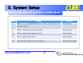
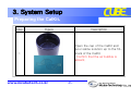
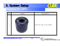
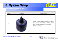
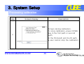
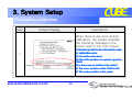
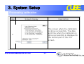
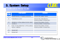
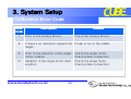
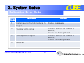
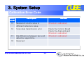
1
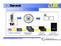
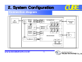
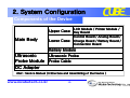
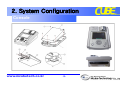
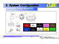
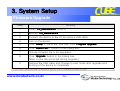
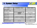
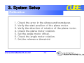
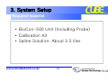
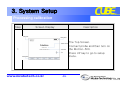
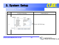
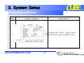
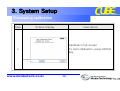
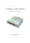
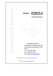
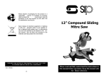
SERVICE TRAINING
Mcube Technology Co., Ltd.
www.mcubetech.co.kr
BioConBioCon-500 Service Training
Contents
1. General System
2. System Configuration
3. System Setup
4. Module Test
5. Troubleshooting
www.mcubetech.co.kr
-2-
1. General
PRINCIPLES (1)
i=n-1
∑
i=0
Gain
Lateral Position
125mL
ultrasonic reflections
www.mcubetech.co.kr
3-dimensional
scanning
-3-
abstract
bladder wall
calculate
bladder volume
1. General
PRINCIPLES (2)
▣ Measuring ultrasonic reflections within a patient's body
- differentiates the urinary bladder from the surrounding tissues.
▣ Measuring ultrasonic reflections on multiple planes
- 3-dimensional scanning
▣ Calculates the patient’s bladder volume with multiple planes
- 3-dimensional images
- more accurate than conventional 2-dimensional ultrasound
▣ Displays bladder volume and bladder image
- you can confirm that the result is reliable with 3D bladder images.
www.mcubetech.co.kr
-4-
2. System Configuration
System block diagram
Connection diagram
Device disassembly
www.mcubetech.co.kr
-5-
2. System Configuration
System block diagram
www.mcubetech.co.kr
-6-
2. System Configuration
Connection diagram
DC
Adapter
J1
Charge
Board
J2
J6
J7
J5
J4
JP101
JP2
JP1
J2
Battery
Module
Battery
Board
J1
Printer
Module
JP2
JP6
JP1
JP7
Analog Board
JP3
JP7
JP4
JP5
JP6
JP4
JP5
Connection Board
JP1
JP2
JP3
JP1
JP2
JP3
PC
J4
Control Board
J2
Key Board
J1
J3
JP5
JP4
LCD Module
www.mcubetech.co.kr
-7-
Ultrasonic
Probe
USB
2. System Configuration
Components of the Device
LCD Module / Printer Module /
Upper Case Key Board
Main Body
Lower Case
Control Board / Analog Board /
Charge Board / Battery Board /
Connection Board
Battery Module
Ultrasonic Probe
Ultrasonic
Probe Module Probe Cable
DC Adapter
*Ref.: Service Manual (3.Structure and Assembling of the Device )
www.mcubetech.co.kr
-8-
2. System Configuration
Console
www.mcubetech.co.kr
-9-
2. System Configuration
Upper Case
www.mcubetech.co.kr
-10-
2. System Configuration
Lower Case
www.mcubetech.co.kr
-11-
2. System Configuration
Ultrasonic Probe Module(1)
www.mcubetech.co.kr
-12-
2. System Configuration
Ultrasonic Probe Module(2)
www.mcubetech.co.kr
1
Red
3
white
5
CoaxialCoaxial-
7
Pink
9
Brown
2
Blue
4
Black
6
Coaxial+
8
Yellow
10
Green
-13-
3. System Setup
Firmware Upgrade
Set the Maintenance Menu
Set the Setup Menu
Calibration
www.mcubetech.co.kr
-14-
3. System Setup
Firmware Upgrade
Step
Activity
1
Install “CS_Maintenance
CS_Maintenance”
CS_Maintenance to a PC.
2
Execute “CS_Maintenance
CS_Maintenance”.
CS_Maintenance
3
Connect the device to the PC by using a USB cable.
4
Turn on the device.
5
Click “Setup
Setup”
Program Upgrade”.
Setup in menu bar, and then click “Program
Upgrade
6
Click “Select
Select File…”
button in the Dialog box.
File
7
Choose firmware file to be upgraded.
8
Click “Upgrade
Upgrade”
Upgrade button in the Dialog box.
(Must not be disconnected during upgrade.)
9
Remove the USB cable and Change to user mode after upgrade and
booting of the device is completed.
The scan data stored is deleted when the Firmware is performed
www.mcubetech.co.kr
-15-
3. System Setup
Maintenance Menu
Item
Cal. Value
Store Mode
System Reset
Available Value
Reset Value
5~20
10
Current / Maximum
Maximum
Return / Reset
(The scan data stored is deleted)
Return
Probe Offset
4 ~ 20
9
Print Density
3 ~ 10
7
Outline Mode
On/Off
On
www.mcubetech.co.kr
-16-
3. System Setup
Setup Menu
Item
Available Value
Reset Value
Clinic Name
-
-
Set Date / Time
-
-
Print Option
Value Only / Raw Image / Walls /
All Planes
Raw Image
Flash Store
On/Off
On
Setup Print
-
-
Scan Result
Contour / B-Mode
B-Mode
Auto Power
Off, 3, 5, 7, 10 minutes
Calibration
-
-
On/Off
On
Prescan Enable
www.mcubetech.co.kr
-17-
5 minutes
3. System Setup
Calibration
1.
2.
3.
4.
5.
6.
7.
Check the error in the ultrasound transducer.
Verify the start position of the plane motor.
Verify the direction of rotation of the plane motor.
Check the plane motor rotation.
Set the angle motor offset.
Check the angle motor rotation.
Set the reference threshold.
www.mcubetech.co.kr
-18-
3. System Setup
Required material
• BioCon-500 Unit (Including Probe)
• Calibration Kit
• Saline Solution: About 2.5 liter
www.mcubetech.co.kr
-19-
3. System Setup
When we should perform calibration?
Item
When
Remark
1
When you upgraded BioCon-500’s program over
Version 3.10
Necessary
2
After replacing Analog Board
Necessary
3
After replacing Digital Board
Necessary
4
After replacing Probe
Necessary
5
Periodical check (Once a year )
Recommended
www.mcubetech.co.kr
-20-
3. System Setup
Preparing the CalKit..
Step
Figure
Description
Open the cap of the CalKit and
pour saline solution up to the fillmark of the CalKit.
Confirm that the air bubble is
absent.
1
www.mcubetech.co.kr
-21-
3. System Setup
Preparing the CalKit..
Step
Figure
Description
Close the cap of the CalKit.
2
www.mcubetech.co.kr
-22-
3. System Setup
Preparing the CalKit..
Step
Figure
Description
Align the probe scan button with
the arrow mark of the Calkit, and
put the probe into the probe
holder firmly.
3
www.mcubetech.co.kr
-23-
3. System Setup
Processing calibration
Step
Screen Display
Description
The Top Screen.
Connect probe and then turn on
the BioCon-500.
Press UP key to go to setup
menu.
1
www.mcubetech.co.kr
-24-
3. System Setup
Processing calibration
Step
Screen Display
Description
Setup Menu
Go to “Calibration” setup using
UP or DOWN key.
2
www.mcubetech.co.kr
-25-
3. System Setup
Processing calibration
Step
Screen Display
Description
Press ENTER key.
3
www.mcubetech.co.kr
-26-
3. System Setup
Processing calibration
Step
Screen Display
Description
Display the “Start” setup value
using LEFT key or RIGHT key
4
www.mcubetech.co.kr
-27-
3. System Setup
Processing calibration
Step
Screen Display
Description
Calibration top screen
To start calibration, press ENTER
key.
5
www.mcubetech.co.kr
-28-
3. System Setup
Processing calibration
Step
Screen Display
Description
Screen during calibration.
To stop calibration, press DOWN
key in the first path or second
path.
In the third path and fourth path,
a user cannot stop the calibration
6
www.mcubetech.co.kr
-29-
3. System Setup
Processing calibration
Step
Screen Display
Description
When there is any error during
calibration, the system displays
the following message in the
bottom part of the LCD screen.
*Common points to be checked in case
of calibration error.
7
1) Check the water level.
2) Check the position of a plastic jig in the
CalKit.
3) Is there any air bubble in the water?
4) The cover position of the CalKit is OK.
5) The probe position in the probe
www.mcubetech.co.kr
-30-
3. System Setup
Processing calibration
Step
Screen Display
Description
The screen when the calibration
is done successfully. The date
and time when the calibration is
done successfully is displayed in
the bottom part of the LCD
screen.
8
www.mcubetech.co.kr
-31-
3. System Setup
Calibration Error Code
Error
Code
Description
Remark
1
Insufficiency of saline solution
Check the water level.
2
Transducer error
Check the transducer
Check probe connection
3
Variation in the plane motor start
position
Check the plane motor
Check probe connection
4
Error in the direction of the plane
motor rotation
Check the plane motor
Check probe connection
5
Reserved
6
Reserved
www.mcubetech.co.kr
-32-
3. System Setup
Calibration Error Code
Error
Code
Description
Remark
7
Error in the Analog Board
8
If there’s no reflection signal from Probe is not in the CalKit.
target.
9
Error in the direction of the angle
motor rotation
Check the angle motor
Check probe connection
10
Variation in the angle motor start
position
Check the angle motor
Check probe connection
www.mcubetech.co.kr
Check the Analog Board
-33-
3. System Setup
Calibration Error Code
Error
Code
Description
11
Distance error from transducer to
target
12
Remark
Confirm that the air bubble is
absent.
Check the Analog Board
Too low echo signal
13
Too high echo signal
14
Reserved
www.mcubetech.co.kr
Frame breakaway
Confirm that the air bubble is
absent.
Check the Analog Board
-34-
3. System Setup
Calibration Error Code
Error
Code
Description
Remark
15
Measured volume value is
different reference value.
(Phantom calibration)
16
Scan data transmission error
Check the Control Board
Check the Analog Board
(Phantom calibration)
17
Big difference between two end
detection algorithms.
(Phantom calibration)
18
Reserved
www.mcubetech.co.kr
-35-
4. Module Test
Analog Board
Ultrasonic Probe
Control Board
www.mcubetech.co.kr
-36-
4. Module Test
Analog Board
Item
Location
Value
Power
TP1(GND) & '+' of L9
+5V (+/- 5%)
Power
TP1(GND) & '-' of L3
-4.8V (+/- 5%)
Power
TP1(GND) & TP8
+7.7V (+/- 5%)
TCG1 Rising Time
TP1(GND) & TP10
5.5 ~ 7.2[us]
TCG2 Rising Time
TP1(GND) & TP11
156 ~ 172 [us]
Ultrasonic Pulse
Peak to Peak
TP1(GND) & TP6
60 ~ 90 [Vpp]
www.mcubetech.co.kr
-37-
4. Module Test
Ultrasonic Probe
Probe Cable Pin No.
Measured Value
Pin 5 & 8
Pin 10 & 11
15(+/-)1 (ohm)
Pin 13 & 15
Pin 16 & 17
Pin 1 & 6
Short (normal) /Open (abnormal)
Pin 1 & 3
Open (button off) / Short (button on)
www.mcubetech.co.kr
-38-
4. Module Test
Control Board
Check point
Check operation of the LCD.
Check operation of the Printer.
Check operation of the Key Board.
Check operation of the Ultrasonic Probe.
Check operation of the USB.
www.mcubetech.co.kr
-39-
5. Troubleshooting
System is not turned on
No.
Check point
Description
1
Is POWER key pressed for more than 1
second?
The system operates when pressing the
POWER key for more than 1 second.
2
Voltage of battery module.
Above +7V
3
Is battery module connected?
If not, connect the module.
4
Connector between the Key Board and
the Control board ?
Connect the connector between two
boards.
5
Control Board – Analog Board
Is connected from the Battery Module to
Analog Board – Charge Board
the Control Board in the right direction?
Charge Board – Battery Board
6
Not solved yet?
www.mcubetech.co.kr
Exchange control boards.
-40-
5. Troubleshooting
System is not turned off
No.
Check point
Description
1
Is POWER key pressed more
than 1 second?
The system operates when
pressing POWER key for more
than 1 second.
2
Turn the power off by
Is the system not turned off
removing the battery module
even when pressing the Power
from the system.
key for more than 1 second?
And exchange control boards.
www.mcubetech.co.kr
-41-
5. Troubleshooting
System turn off while in use
No.
Check point
Description
1
Is auto power-off on in the
setup menu?
When auto power-off
function is active, system
will be turned off if no key
input is made during the
fixed time.
2
Is the system turned off with
the message of “BATTERY
LOW, SYSTEM WILL BE
TURNED OFF”?
Turn off the system to protect
the battery module if the
power is insufficient. Try
again after charging.
www.mcubetech.co.kr
-42-
5. Troubleshooting
Initial screen is not display after turn-on
No.
Check point
Description
1
Is backlight on in LCD?
Check if the connector for backlight
of LCD is connected.
2
Is the FPC connector to the LCD module
well connected?
Check if the connector is connected
properly.
3
Check the voltage between the Control
Check if -23V (+/-1V).
board ground and 12th pin of JP5.
4
Check the voltage between the Control
Check if -18V (+/-1V).
board ground and 13th pin of JP5.
5
Is the system turned off?
Retry after replacing the LCD module.
6
The system is not turned off.
Test again after replacing the Control
board.
www.mcubetech.co.kr
-43-
5. Troubleshooting
Green LED is not turned on with adapter being connected
No.
Check point
Description
1
Is green LED not turned on even
when the system is OFF?
2
Is the 4 pin connector connecting the Check the connection status and if
Key Board and the Charge Board
not connected, connect 4 pin
connected?
connector.
3
Not solved yet?
Replace the Charge Board.
4
Green LED is on when the system is
OFF, but it is turned off when the
system is ON.
No problem.
Because of charging control in
Control board sometime Green LED
is off when system is on.
www.mcubetech.co.kr
Yes ->Refer to item 2.
No -> Refer to item 4
-44-
5. Troubleshooting
NO SCANHEAD Error Message
No.
Check point
Description
1
Is the ultrasonic probe
connected to the main body?
If not, NO SCANHEAD
message is displayed when
the scan button is pushed.
2
Is open between the the 1st and
6th pin of the probe connector?
Test again after replacing
with other ultrasonic probe.
3
The message is displayed when
Request service from the
the 1st and 6th pin of Probe
headquarter
connector is short
www.mcubetech.co.kr
-45-
5. Troubleshooting
NO PAPER Error Message
No.
Check point
Description
1
Does printer module have
thermal paper?
If not, insert thermal paper.
2
Does message still appears
even when there is paper?
Try again after replacing the
control board.
www.mcubetech.co.kr
-46-
5. Troubleshooting
Image after SCAN(1)
• Image showing the
scan result is set as
CONTOUR
• Normal Image
• Scanned image from
open object (in air).
www.mcubetech.co.kr
-47-
5. Troubleshooting
Image after SCAN(2)
• Image ,when the
transducer connection is
open.
• Check using the
Calibration Kit.
• Error in transducer
connection.
• Retry after replacing the
probe
www.mcubetech.co.kr
-48-
5. Troubleshooting
Image after SCAN(3)
• Check if ‘SCAN RESULT’ is set as ‘CONTOUR’.
• Yes, retry after setting as ‘B-MODE’.
• No, request service from the headquarter.
www.mcubetech.co.kr
-49-
5. Troubleshooting
Error in Motor Rotation
No.
Check point
1
Check error in motor.
Measure the resistance of each
case in probe Connector
1) Pin number 5 and 8
2) Pin number 10 and 11
3) Pin number 13 and 15
4) Pin number 16 and 17
Normal resistance value
15 +/- 1 (Ohms)
In case of normal resistance.
Retry after replacing analog
board.
2
www.mcubetech.co.kr
Description
-50-
5. Troubleshooting
Printing Error (No feeding)
No.
Check point
Description
Thermal Paper
No paper.
Properly insert.
2
Motor sound?
Yes, goto 3
No, check the printer connector
3
Not solved?
Replace control board.
1
*Paper Spec. : 57mm(width), ø30mm
www.mcubetech.co.kr
-51-
5. Troubleshooting
Battery Management
1) After full charging (for battery module with full capacity)
scan : 4 hours(one scan per 15sec)
standby : 6 hours
2) Full charging Time : about 10 hours (MAX)
3) Battery Module is supply ( with 6 months warranty )
www.mcubetech.co.kr
-52-
Discussions
Any Questions???
www.mcubetech.co.kr
-53-
Thank You
ADDRESS #803, Shinnae-Technotown, 485, Sangbong-Dong, Chungrang-Gu
Seoul, Korea 131-220
TEL
82-2-3421-7780
FAX
82-2-3421-7076
URL
www.mcubetech.co.kr