1
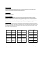
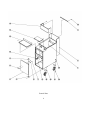
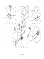
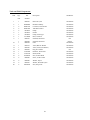
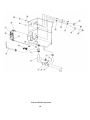
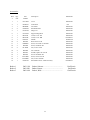
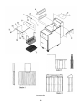
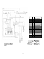
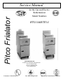
Service Manual
Pitco Frialator
for the Gas and Electric
Rethermalizer
Literature # L20-159 Rev 1
Model Numbers
RTG14&RTE14
PITCO FRIALATOR, INC.
P.O.BOX 501 CONCORD, NH 03302-0501
Phone: 1(603)225-6684
Toll Free: 1(800)258-3708
Fax: 1(603)225-8497
Rev Date 30 April 1997
Made in the United States of America
NOTICES
There are three different types of notices that you should be familiar with, a NOTICE, CAUTION,
and WARNING. A NOTICE is a special note used to call attention to a particularly important
point. CAUTION is used to point out a procedure or operation which may cause equipment
damage. The WARNING notice is the most important of the three because it warns of an operation
that may cause personal injury. Please familiarize yourself with your new Rethermalizer before
operating it and heed the notices throughout this manual. The WARNINGS are listed below and on
the following page for your review prior to operating the unit.
FOR YOUR SAFETY
DO NOT store or use gasoline or other flammable vapors or liquids in the vicinity of this
or any other appliance.
WARNING: Improper installation, adjustment, alteration, service or maintenance can
cause property damage, injury or death. Read the installation, operating and
maintenance instructions thoroughly before installing or servicing this equipment.
TO THE PURCHASER
POST IN A PROMINENT LOCATION INSTRUCTIONS TO BE FOLLOWED IN
THE EVENT THAT AN OPERATOR SMELLS GAS. OBTAIN THIS INFORMATION
FROM YOUR LOCAL GAS SUPPLIER.
SAFETY
SAFETY
SAFETY
WARNING
This appliance is equipped with a three prong (grounding)
plug. This is for your protection against shock hazard in
the event of equipment malfunction. Always plug the unit
directly into a properly grounded three-prong receptacle.
DO NOT cut or remove the grounding (third) prong.
WARNING
DO NOT use an open flame to check for gas leaks! Keep
all open flames away from the Rethermalizer until the
installation is complete.
WARNING
A Rethermalizer equipped with casters and a flexible
power cord, must be connected to the gas supply with a
Quick-Disconnect device. This quick disconnect must
comply with ANSI Z24.41. To limit the movement of the
unit without depending on the connector or quick
disconnect, a restraining cable must also be installed.
WARNING
There is an open gas flame inside the Rethermalizer. The
unit may get hot enough to set nearby materials on fire.
Keep the area around the unit free from combustibles.
WARNING
Ensure that the Rethermalizer can get enough air to keep
the flame burning correctly. If the flame is starved for air
it can give off a dangerous carbon monoxide gas. Carbon
Monoxide is a clear odor-less gas that can cause
suffocation.
WARNING
Carbon monoxide can build up if you block the flue.
Blocking the flue will also cause the unit to overheat. DO
NOT obstruct the flow of combustion/ventilation or air
opening around the Rethermalizer. Ensure that you meet
the minimum clearances specified in the installation
instructions. Adequate clearance around the unit is
necessary for servicing and proper burner operation.
WARNING
Wait 5 minutes before attempting to relight the pilot.
This will allow for any gas in the unit to dissipate.
SAFETY
SAFETY
SAFETY
SAFETY
WARNING
The power supply must be disconnected before servicing
or cleaning the appliance.
WARNING
DO NOT supply the fryer with a gas that is not indicated
on the data plate. If you need to convert the fryer to
another type of fuel, contact your dealer.
WARNING
The Rethermalizer must be properly restrained to prevent
movement or tipping. This restraint must prevent the unit
from movements that would splash hot liquids on
personnel. This restraint may be by any means (alcove
installation, adequate ties, or battery installation).
WARNING
DO NOT obstruct the flow of combustion/ventilation or
air openings around the rethermalizer. Adequate
clearance around the rethermalizer is necessary for
servicing and proper burner operation. Ensure that you
meet the minimum clearances specified in the installation
instructions.
WARNING
The Rethermalizer must be properly restrained to prevent
movement or tipping. This restraint must prevent the
fryer from movements that would splash hot liquids on
personnel. This restraint may be any means (alcove
installation, adequate ties, or battery installation).
WARNING
NEVER supply the Rethermalizer with a gas that is not
indicated on the data plate. Using the incorrect gas type
will cause improper operation. If you need to convert the
unit to another type of fuel, contact your dealer.
THIS MANUAL MUST BE
RETAINED FOR FUTURE
REFERENCE
SAFETY
SAFETY
SAFETY
Table of Contents
Table of Contents
TROUBLESHOOTING
Component Diagnosis
ii
1
1
Digital Control
Computer
Water Level Control
Water Fill Solenoid
Safety Relay (K1)
1
1
1
1
2
Ignition Control Module
Temperature Probe
PARTS
General Parts
Heating Components
2
2
3
3
5
Front Panel Assembly
Tank and Fluid Components
Accessories
SCHEMATICS
RTG14 with Digital Control
7
9
11
14-17
14
RTE14 with Digital Control
15
TROUBLESHOOTING
This section is provided to aid the Authorized Service Technician in the repair of your Rethermalizer.
SYMPTOM
POSSIBLE CAUSE
Display will not light
Bad Temperature Control, Fuse Holder, Fuse, Transformer or Switch
Maintains wrong temperature
Bad Probe or Display
Display lit, but does not heat
Bad K1 Relay, contactor, Probe, Display, Gas Valve or Elements or
Water Level control.
Constantly fills, or will not fill
Bad K1 Relay, Level Sensor Seals, Level Control or Water fill solenoid.
Manual bypass valve may be open.
Spark can be heard, Pilot does not light
Gas Valve Knob is NOT in the ON position? Plugge Pilot orifice. Bad
Ignition Module or Gas Valve.
Pilot Lights but mains do not.
Bad Gas Valve or Ignition Module.
Component Diagnosis:
Before diagnosing any individual components, all appropriate power supplies and wiring terminations must be checked.
Follow the appropriate section below to diagnose the suspected components.
Digital Control:
When 24 VAC is supplied to the Temperature Control, and the control is turned on the display should be lit.
When the water temperature is below the SET Temperature (195°F) 24 VAC Heat Demand signal can be found
between the Gray and Green/Yellow wires at the rear of the controller. The Red LED Heating indicator light will
be ON. When problems with the Temperature Control occur it is important that the Probe be checked also.
Computer Control:
When 24VAC is supplied to the control the display should be lit. When the water temperature is below the SET
Temperature (195°F) a 24VDC Heat Demand signal can be found at the coil of the Heat Demand Relay located
behind the computer.
Water Level Control:
Check for 24 VAC between the COM and 24 V PWR (Power) terminals. Disconnect the HIGH, LOW and COM
terminals, a 24 VAC signal can now be seen between the N.C. and COM terminals. The safety Relay (Kl) and
the Water Fill Solenoid will energize. Using a jumper wire, short the HIGH, LOW and COM terminals together,
this will cause the Control to stop the 24 VAC signal between the N.C. and 24 V PWR terminals.
1
Water Fill Solenoid:
The Water Fill Solenoid should be open when a 24 VAC signal is applied to the two wires leading to the
Actuator. With no voltage present the Solenoid should be closed.
Safety Relay (K1):
With a 24 VAC signal present at the coil section of the relay the switch section should have closed the circuit
between the two Gray wires.
Ignition Control Module:
When the Ignition Control Module receives 24VAC it will send a signal to the spark ignitor at the pilot
assembly. The Module will also send 24VAC to the Pilot Solenoid at the Gas Valve. The pilot will light and
the Pilot Flame Sensor will send a 0.15-0.35 micro amp signal to the Ignition Module at which time the
ignition module will cease the pilot spark and send a 24VAC signal to the Main Solenoid at the Gas Valve. To
test the system look and listen for the above ignition steps and check for the appropriate signals.
Temperature Probe:
Unplug the wiring harness from the rear of the Temperature Control. Measure the resistance between the two
black wires on the harness in the cooker, NOT the harness at the control. Measure the water temperature (with
an independent temperature meter or thermometer) and the resistance of the probe at the same time. Consult
the chart below for probe specifications.
Temperature
°F
Resistance
Ohms
Temperature °F Resistance
Ohms
108050
130°F
27862
190°F
8994
80ºF
84643
140°F
22755
195°F
8255
90°F
66823
150°F
18694
200°F
7585
100°F
53145
160°F
15446
210°F
6427
110°F
42568
170°F
12832
212°F
6221
120°F
34328
180°F
10716
Temperature
ºF
Resistance
Ohms
70°F
If the resistance varies more than 20% from that specified in the chart the probe should be changed. It is more
important that the probe resistance be correct at 212°F that 70°F, therefore there can be more tolerance given
at 70°F than at 212°F.2
PARTS
General Parts:
Item
QTY/
Part
Description
Gas/Electric
#
Unit
Number
1
1
B3310502-C
Tank
Gas
3
4
5
1
1
1
1
1
1
B3402201
B1811501
B1811503
A1619202
B2301109
B7230302
Tank
Cabinet, Painted
Cabinet, Painted
Back Strip
Door
Hinge, Bottom Right Hand Door
Electric
Gas
Electric
Gas
Gas/Electric
Gas/Electric
6
7
8
9
10
1
2
2
1
1
B7230202
P6071483
PP10025
PP11006
P6071300
Hinge, Top Right Hand Door
Plug, Hole
Screw
Handle
Magnet
Gas/Electric
Gas/Electric
Gas/Electric
Gas/Electric
Gas/Electric
11
12
13
14
1
1
1
1
1
4
2
2
4
16
16
A1819602
B3609901
A1822101
A4103602
A4103902
P0075300
PP10728
PP10652
A3901101
P0020600
P0093300
Bracket, Door Magnet
Edge, Marine
Cabinet Spacer, Tank Holder
Splash Back
Splash Back
Screw, 3 #10 x 5/8" Self Drill
Caster With Brake
Caster Without Brake
Caster Mounting Plate
Bolt 1/4-20
Nut 1/4-20
Gas/Electric
Gas/Electric
Gas/Electric
Gas
Electric
Gas/Electric
Gas/Electric
Gas/Electric
Gas/Electric
Gas/Electric
Gas/Electric
2
15
16
17
18
19
20
3
General Parts
4
Heating Components:
Item
QTY/
Part
Description
Gas/Electric
#
Unit
Number
1
1
P6071767
Gas Shut-Off Valve
Gas
2
3
4
5
6
1
2
2
1
2
P6071450
PP10665
PP10665
A3306402
P0092300
Pilot Assembly, Nat
Screw 10-24x3/8" SS
Screw 10-24x3/8" SS
Pilot Bracket
Nut, Keep 10-24
Gas
Gas
Gas
Gas
Gas
7
8
9
10
11
12
13
14
15
16
17
18
19
1
1
1
1
1
1
1
1
1
2
2
2
4
PP10271
A1815501
A8000801
A8013101
B7510102
B8009501
A8000801
A4012801
P0063500
A8001001
PP10025
P6071050
PP10195
High-Limit
Bracket, High-Limit
Bracket, Manifold Mounting RH
Bracket, Thermostat & Unitrol Extension ,
Extension, Gas Valve Knob
Manifold, Burner
Bracket, Manifold Mounting LH
Clamp, Unitrol Bracket
Screw, Square Head 6-32
Air Collar
Screw, Air Collar Set
Burner
Bolt, Burner Mounting, 1/4-20
Gas
Gas
Gas
Gas
Gas
Gas
Gas
Gas
Gas
Gas
Gas
Gas
Gas
20
21
22
23
25
1
2
1
2
2
1
1
2
A1401002
PP10698
A3701002
P6071341
P6071353
P5045638
P5045639
A8001101
Clamp, Bulb and Probe
Screw, 10-24 Round Head SS
Heat Shield, Burner
Orifice, NAT
Orifice, LP
Gas Valve 24V NAT
Gas Valve 24V LP
Fittings, Burner
Gas
Gas
Gas
Gas
Gas
Gas
Gas
Gas
26
27
28
29
2
1
1
1
P6071267
P5045660
B6779850
P5047541
Knob, Gas Valve
Bracket
Unitrol Limit Wires
Thermopile
Gas
Gas
Gas
Gas
24
Not Shown
3
PP10953
Elements 208/220/240V .....................................
5
Electric
Heating Components
6
Front Panel Assembly:
Item
Qty/
Part
Description
Gas/Electric
#
Unit
Number
1
1
B3609601
Front Panel Weldment
Gas/Electric
2
3
4
5
6
7
8
10
2
1
1
4
1
1
1
1
2
1
1
P0075300
A3635002
PP10939
PP10195
PP10654
A6054501
PP10122
P5045717
P5045794
P5045794
B6718701
Screw 3 10 x 5/8" Self Drill
Bezel Front Panel
Thermostat With 24V Display
Screw, Button Head Hex
Switch, Rocker SPST
Label, Switch
Fuse, 1 Amp Slow Blow, Glass
Fuse, 2 Amp Slow Blow, Glass
Fuse Holder
Fuse Holder
Probe, Temperature Sensing
Gas/Electric
Gas/Electric
Gas/Electric
Gas/Electric
Gas/Electric
Gas/Electric
Gas
Gas/Electric
Gas
Electric
Gas/Electric
11
12
13
14
15
1
1
1
8
1
PP 10439
PP10146
PP10210
PP10749
PP10702
Cable, Power With Plug
Strain Relief 90°
Transformer Multi to 24 VAC
Screw 6-32 x 5/8
Control, Liquid Level
Gas/Electric
Gas/Electric
Gas/Electric
Gas/Electric
Gas
1
1
1
2
1
4
9
1
PP10981
P5046691
P5046688
P6071071
P6071223
PP 10749
P0091400
A2948301
P5045240
B6714301
B6731302
B6714101
B6731402
Control, Liquid Level
Relay 120 VAC SPST
Relay 24 VAC SPST
Wire Clamp
Grommet
Screw 6-32 x 5/8" SS
Nutsert 6-32
Entrance Box
Clamp, Romex
Harness, Control Cable
Harness, Entrance Box
Harness, Front Panel
Harness, Front Panel
Electric
Gas
Electric
Gas/Electric
Gas/Electric
Gas/Electric
Gas/Electric
Gas/Electric
Gas/Electric
Gas
Electric
Gas/Electric
Electric
9
16
17
18
19
20
21
22
23
24
Not Shown
1
2
PP10560
P5047302
Contactor, 24 VAC, 3 Pole.................................
Terminal Block...................................................
7
Electric
Electric
Front Panel Assembly
8
Tank and Fluid Components:
Item
Qty/
Part
Description
Gas/Electric
Unit
Number
1
1
PPI0565
Drain Valve, SS
Gas/Electric
2
3
4
5
6
7
8
9
10
11
1
2
2
2
1
2
1
1
1
1
1
B4000802
B8015102
B8015202
PP10034
PP10032
PP10620
A3318602
PPI0747
PP10982
PPI0742
PP10753
Handle Assembly
Connector, Drain Outlet
Tube Drain Outlet
Clamp
Gasket
Clamp, Worm type
Hose, Overflow
Solenoid, Water Fill
Solenoid, Water Fill
Filter
Valve, Ball 3/8" Bronze
Gas/Electric
Gas/Electric
Gas/Electric
Gas/Electric
Gas/Electric
Gas/Electric
Gas/Electric
Gas
Electric
Gas/Electric
Gas/Electric
12
13
14
15
16
17
18
19
20
1
4
1
1
2
2
4
2
2
PP10726
PP10663
A3318002
A3318102
P0142000
PPI0698
PPI0666
PP10667
P0092300
Valve, Check (Non Return)
Plug, SS 1/4 NPT
Deflector, Water Inlet
Shield, Probe
Nut,Acom 10-24 SS
Screw, 10-24 x 5/8 SS
Washer, Nylon
Washer, Shoulder Nylon
Nut, Keep 10-24
Gas/Electric
Gas
Gas/Electric
Gas/Electric
Gas/Electric
Gas/Electric
Gas/Electric
Gas/Electric
Gas/Electric
9
Tank and Fluid Components
10
Accessories:
Item
Qty/
Part
Description
Gas/Electric
#
Unit
Number
1
1
A3317902
Cover
Gas/Electric
2
3
4
5
1
1
2
1
A4509301
B4509402
A5053602
A3318704
Tube Rack
Taco Rack
Pan Holder End
Hinge rod
Gas
Gas/Electric
Gas/Electric
Gas/Electric
6
7
8
9
10
11
1
1
1
1
2
1
A3317802
B3311001
B3311002
P6071251
PP10670
P0048980
Support Hinge Rod
Catch, Cover - LH
Catch, Cover - RH
Handle
Bolt 1/4-20 x 1" SS
Screw, 10-32 with 1" shoulder
Gas/Electric
Gas/Electric
Gas/Electric
Gas/Electric
Gas/Electric
Gas/Electric
12
13
14
15
16
17
3
2
2
1
1
1
PP10698
PP 10668
PP10669
PP10673
PP10729
PO112000
Screw, 10-24x5/8" SS
Nut, Acorn 1/4-20
Nut 1/4-20 SS
Washer, Split Lock 1/4" SS
Screw 1/4-20x3/8" SS
Screw, 10-24 x 1/2" SS
Gas/Electric
Gas/Electric
Gas/Electric
Gas/Electric
Gas/Electric
Gas/Electric
18
19
1
1
PO142000
A5053702
Nut, Acorn 10-24 SS
Pan Holder Center - Dual Units Only
Gas/Electric
Gas/Electric
Basket 1
Basket 2
Basket 3
B4511101
B4511501
B4511601
Basket, Suitcase..............................................
Basket, Narrow...............................................
Basket, Wide...................................................
11
Gas/Electric
Gas/Electric
Gas/Electric
Accessories
12
Drawing showing the location of the Pilot Assembly with the Burner
Shield in place.
13
K1
P5046691
RELAY, 120 VAC - SPDT W/MTG TABS
V2
A2
A1
PP 0682
PP 0797
PP 0949
VALVE, WATER - 120V SOLENOID
CONTROLLER, LIQUID LEVEL-RELAY
THERMOSTAT, DIGITAL - 24V
RT1
S1
P3
J3
F1
T1
S12
P11
P2
P1
P4,P7,P36
P9
J1
J11
F2
PP 0939
PP 0654
PP10202
PP10203
PP10122
PROBE, TEMPERATURE
SWITCH, ROCKER -SPST (ON-OFF)
CONNECTOR, PLUG-4 PIN MOLEX
V1
J4,J7,J36
NOMENCLATURE
PP10210
PP10084
P504S860
PP10090
P5045829
PP10439
PP10089
P5045838
P5045717
P5045638
P5045639
P5045839
PART NO
CONNECTOR, JACK-* SKT MOLEX
FUSE. GLASS-1 AMP SLOW BLOW
XFMR. 40VA - 120/208/240V TO 24V
SWITCH, HIGH TEMPERATURE LIMIT
CONNECTOR, PLUG-9 PIN MOLEX
CONNECTOR. PLUG-15 PIN MOLEX
CONNECTOR, PLUG-3 PIN MOLEX
CONNECTOR. PLUG-2 PIN MOLEX
CORD. PLUG-MOLD 14-3 NEMA 5-15P
CONNECTOR, JACK-3 SKT MOLEX
CONNECTOR, JACK-9 SKT MOLEX
FUSE, 2 AMP-SLOW BLOW (GLASS)
VALVE, GAS UNITROL BMSER 24 VAC (NAT)
VALVE, GAS UNITROL BMSER 24 VAC (PRO)
CONNECTOR, JACK-2 SKT MOLEX
DESCRIPTION
PARTS LIST
NOTES:
1. UNLESS OTHERWISE SPECIFIED ALL WIRES ARE 1 8 AWG.
2. AT FUSES F1 AND F2, USE FUSE HOLDER (P5M5T94).
3. JUMPER TERMINAL +5 TO TERMINAL -3 ON A1 FOR
PROGRAMMING.
14