1
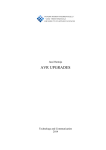
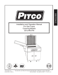
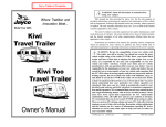
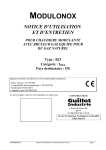
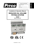
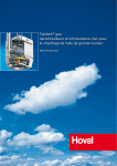
IMPORTANT FOR FUTURE REFERENCE
Please complete this information and retain this
manual for the life of the equipment:
Model #:________________________
Serial #: ________________________
Date Purchased: _________________
14R & 18 WKS
KENTUCKY FRIED CHICKEN
EQUIPPED WITH A FAST COOKING
COMPUTER: EM99 or VC210
FRONT PANEL SUPPLIED BY PITCO
TROUBLESHOOTING
MANUAL
PITCO FRIALATOR, INC
P.O. BOX 501
CONCORD, N.H. 03301
PHONE 603-225-6684
SERVICE DEPT. 603-225-5688
L20-310 rev 0 (04/07)
SERVICE MANUAL
14R & 18 WKS
KENTUCKY FRIED CHICKEN
CONTENTS
Section 1S Service Procedures
- Burner Flow Drawing
Section 2S Troubleshooting Charts
Section 3S Parts List
Section 4S Front Panel Bezel
- Orifice Tips & Burner Pressure
Section 5S Entrance Box
L20-310 REV 0 (04/07)
Pitco Frialator, Inc.
P.O. Box 501, Concord, New Hampshire
SECTION 1S SERVICE PROCEDURES
Parts can be identified from diagrams on Parts List page for each model.
1.1
TO REMOVE MAIN BURNER
a. Turn Unitrol knob to “OFF" position.
b. Loosen set screw in base of burner casting.
c.
Unscrew and remove two hex head screws at top of burner.
d. Unscrew and remove air collar from burner.
e. Lift burner up to clear top of burner fitting and remove from fryer.
f.
1.2
Reverse procedure to remount burner.
TO CHANGE MAIN BURNER ORIFICE
a. Follow procedure in Section 1.1.
b. After burner has been removed, unscrew orifice with 3/8” wrench.
c.
Screw in new orifice – tighten gas tight.
d. Remount burner and air collar.
1.3
TO REPLACE HEAT TUBE BAFFLES
a. Remove main burners: follow procedure in Section 1.1.a. through e.
b. Baffles are fastened to the inside of the heat tube by a small tack weld on the right
hand front baffle support. Break leg away from weld with a chisel or solid steel bar.
c.
Remove old baffles and insert new ones in tubes in original position.
d. Remount main burners.
1.4
TO REMOVE PILOT BURNER
a. Follow procedure in Section 1.1 and remove main burner to the right of the pilot
burner.
b. Unscrew and remove tubing nut from pilot tubing connection on Unitrol.
c.
Unscrew and remove thermopile or thermocouple from connection on Unitrol.
d. Unscrew and remove the two screws holding the pilot to the bracket on the fry tank
and lift the entire pilot assembly out of the fryer.
1.5
TO CHANGE PILOT BURNER ORIFICE
a. Follow procedure in 1.4.
b. Unscrew tubing nut in fitting in base of pilot burner.
c.
Unscrew fitting in the base of pilot burner and withdraw orifice from inside the fitting.
d. Insert new orifice and reverse procedure to re-assemble.
e. Tighten all screws and connections and test for gas leaks.
Pitco Frialator, Inc.
P.O. Box 501, Concord, New Hampshire 03301
SECTION 1S SERVICE PROCEDURES (Cont’d)
1.6
TO REPLACE THERMOPILE OR THERMOCOUPLE
a.
Follow procedure in 1.4.
b. Unscrew and remove thermopile or thermocouple from pilot burner and bracket.
c.
Replace with new thermopile or thermocouple.
d. Reverse procedure to re-assemble.
e. Tighten all screws and connections and test for gas leaks.
1.7
TO ADJUST PILOT FLAME
a.
Make this adjustment with pilot burner lit.
b. Remove screw cap underneath pilot supply tubing connection to Unitrol valve.
c.
Insert long handled screwdriver with 1/8” wide blade in adjusting screw slot inside this
pilot supply fitting.
d. Turn adjusting screw clockwise to decrease or counterclockwise to increase pilot
flame. Watch size of pilot flame while turning adjusting screw.
CAUTION DO NOT REMOVE ADJUSTING SCREW
e.
Replace screw cap when desired flame size is obtained.
f.
Replace pilot orifice if desired flame cannot be obtained by adjustment. See
procedure 1.5.
1.8
TO REPLACE LIMIT CONTROL
a.
Turn Unitrol knob to “OFF.”
b. Drain all shortening from fry tank. Remove tube screen.
c.
Unscrew and remove the two screws in the limit bulb clamp on the heat tube inside
the fry tank.
d. Take sensing bulb out of the clamp and straighten the capillary tubing.
e. Remove the two burners that are in front of the capillary connector fitting on the
bottom of the fry pot. See procedure 1.1.
f.
Unscrew small hex nut in connector fitting of control to be replaced.
g. Unscrew large connector nut and withdraw capillary and bulb from fry tank.
h. Remove the two wires off the limit control terminals.
i.
Unscrew and remove the two mounting screws in the limit control bracket and
remove the limit control from the fryer.
j.
Unpack the new limit control and carefully unroll the capillary tubing and straighten it
out.
k.
Install the new limit control by reversing the procedure. BE CAREFUL NOT TO
BEND, KINK OR TWIST THE CAPILLARY TUBING SHARPLY. THIS WILL
DESTROY THE LIMIT CONTROL.
PITCO Frialator, Inc.
P.O. Box 501, Concord, New Hampshire 03301
SECTION 2S TROUBLESHOOTING CHART
TROUBLE
Pilot will light but Unitrol
pilot gas valve will not hold
open automatically.
POSSIBLE CAUSE
REMEDY
1
Pilot thermopile or
thermocouple not hot enough
to generate required
millivoltage.
1
Hold Unitrol knob (in PILOT
position) depressed for 1
minute or longer. Make sure all
air has been purged from gas
line.
2
Loose wire connection in
millivoltage circuit.
2
Check all wire connections.
3
Thermopile or thermocouple
producing insufficient
millivoltage.
3
Check voltage at Unitrol with
millivoltmeter, holding pilot
flame on manually as in No. 1
above. Reading should be 500
+/-50 mv. for thermopile.
Reading should be between 25
and 35 mv. for thermocouple.
4
High limit control may have cut
out.
4
Check continuity across limit
control terminals with meter. If
limit control has cut off, check
at what temperature it cut off.
5
Pilot flame too small.
5
Check millivoltage as above;
increase size of flame with
Unitrol pilot adjusting screw.
6
Pilot flame burning yellow.
6
Remove and clean pilot and
thermopile or thermocouple;
decrease size of flame with
Unitrol pilot adjusting screw if
over 450 mv. Reading should
be 500 +/-50 mv. for
thermopile. Reading should be
between 25 and 35 mv. for
thermocouple.
7
Draft may be pulling flame off
thermopile or thermocouple.
7
Eliminate the draft.
8
Gas pressure too low.
8
Pressure at burner manifold
should be 4.0" w.c. for natural
gas and 10.0" w.c. for propane
with all equipment on line in
full operation. If this cannot be
maintained, consult gas
company.
PITCO Frialator, Inc.
P.O. Box 501, Concord, New Hampshire 03301
SECTION 2S TROUBLESHOOTING CHART (Cont'd)
TROUBLE
Pilot will light but Unitrol pilot
gas valve will not hold open
automatically.
POSSIBLE CAUSE
9
Defective thermopile or
thermocouple
10 Defective thermopile or
thermocouple
Pilot flame lit but burners will
not light.
Pilot flame and main
burners cut off while
cooking.
Fryer temperature recovery
too slow.
Pilot flame is yellow.
REMEDY
9
Replace thermopile or
thermocouple
10 Replace magnet
1
Unitrol valve handle not turned
to ON.
1
Turn handle counter clockwise
as far as it will go.
2
Float switch bulb off or stuck
down.
2
Install float switch bulb and new
clip.
3
Supply cord may not be
plugged in or switch may not be
turned on.
3
Check electric supply circuit
4
Defective probe.
4
Replace probe.
5
Defective computer.
5
Replace Computer.
6
Defective Unitrol.
6
Replace Unitrol.
1
Hi-Limit tripped
1
Reset
1
Dirty burners.
1
Clean.
2
Low gas pressure.
2
Minimum operating pressure:
Natural Gas- 4.0" w.c.;
Propane Gas- 10.0" w.c.
3
Incorrect burner orifices.
3
4
Carbon build-up on heat tubes.
4
Call factory to learn proper
sizes.
Clean fry tank and tubes.
5
Baffles in heat tubes may be
burned out.
Pilot flame too large.
5
Replace baffles.
1
Adjust Unitrol pilot adjustment
screw.
Carbon build-up on thermopile
or thermocouple.
2
Remove and clean.
1
2
PITCO Frialator, Inc.
P.O. Box 501, Concord, New Hampshire 03301
SECTION 2S TROUBLESHOOTING CHART
TROUBLE
Burner flames will not enter
heat tubes.
POSSIBLE CAUSE
1
Downdraft on fryer flue
opening, or vent not turned on.
REMEDY
1
Protect flue opening from
downdrafts, breezes or air
flows from blowers.
a. Turn Vent on.
Main burners will not shut
off automatically.
Main burner flames are
yellow.
Howling or screeching noise
when burners are on.
2
Orifices may be incorrect size.
2
Call factory to learn proper
sizes.
3
Gas pressure too high/low.
3
On natural gas adjust Unitrol
pressure regulator to 4.0" w.c
operating pressure. On
propane gas have gas supplier
adjust tank pressure to provide
10.0" w.c. operating pressure
at the fryer. (See Orifice and
Burner pressure chart)
4
Burners out of alignment.
4
Loosen burner mounting
screws and line up burners.
1
Clogged vent cap on Unitrol.
1
Remove and clean cap.
2
Defective Unitrol.
2
Replace Unitrol.
1
Improper air collar adjustment
1
Remove and clean cap.
2
Main burners dirty.
2
Remove burners and clean.
3
Improper gas pressure.
3
On natural gas adjust Unitrol
pressure regulator to 4.0" w.c
operating pressure. On
propane gas have gas supplier
adjust tank pressure to provide
10.0" w.c. operating pressure
at the fryer. (See Orifice and
Burner pressure chart)
4
Orifices are too large.
4
Call factory to learn proper
sizes.
1
Gas pressure too high.
1
Adjust pressure regulator.
2
Dirt or burr on burner orifice.
2
Clean orifice or replace.
NOTES
SECTION 3S EXPLODED PARTS LIST MODEL 14R & 18 WKS
SECTION 3S EXPLODED PARTS LIST MODEL 14R & 18 WKS
ITEM #
1
3
4
5
6
7
8
9
10
11
12
14
15
17
18
20
21
22
23
24
26
27
28
29
30
31
32
33
37
38
39
PART NUMBER
B3309902
B3307201
P5047210
P5047541
P5047540
P6071450
P6071449
B6779850
P5045650
P5045652
P5045638
P5045639
PP10777
PP10778
P6071269
Contact Factory
P6071051
P6071338
P6071309
P6071339
P6071353
See Orifice Chart
A8001001
A8001101
B8005601
PP10025
PP10368
B2301105
B2301106
PP11006
P6071496
PP11261
P6071300
A1400202
A3301001
B1000601
B1000801
A4500201
P6072186
A2510101
A1100108
A1100110
P6072145
Front Bezel Assembly
PP10810
B3900408
B3901401
A8000801
Entrance Box Assembly
ITEM DESCRIPTION
Stainless Steel Fat Container (14R)
Stainless Steel Fat Container (18)
Hi limit Control
Thermopile
Thermocouple
Pilot Burner Natural
Pilot Burner Propane
Unitrol Limit Wire
Unitrol Natural 120V (Thermopile)
Unitrol Propane 120V (Thermopile)
Unitrol Natural 24V (Thermopile)
Unitrol Propane 24V (Thermopile)
Unitrol Natural 24V CE (Thermocouple)
Unitrol Propane 24V CE (Thermocouple)
Unitrol Knob
Data Plate
Main Burners
Burner Orifices Natural (14R)
Burner Orifices Propane (14R)
Burner Orifices Natural (18)
Burner Orifices Propane (18)
See Section 3S Burner Orifices chart (CE)
Air Collar
Burner Fittings
Manifold
Main Burner Bolt
Drain Valve 1 1/4"
Door Assembly RH (14R)
Door Assembly RH (18)
Door Handle
Snap Buttons
Burner Mounting Bolts
Magnetic Door Catch
Probe and Limit Bulb Clamp
Clean Out Rod
Heat Tube Baffles (14R)
Heat Tube Baffles (18)
Tube Screen (14R)
Tube Screen (18)
Drain Extension
Basket Hanger (14R)
Basket Hanger (18)
Basket (14R)
See Section 4S Front Bezel Assembly
7" Caster-Swivel Non-Locking-Rear
7" Leg-Front
8" Caster/Leg Set-Swivel Non-Locking-Rear
Manifold Bracket
See Section 5S Entrance Box
SECTION 3S EXPLODED PARTS LIST MODEL 14R & 18 WKS
ORIFICE TIPS & BURNER PRESSURE
14R Natural
ORIFICE TIP
GAS CATEGORY
SIZE (mm)
I2H, I2E
I2L
I2E+, I2ESI
I2ELL
2.44
2.79
1.17(4)
2.44/2.79
18 Natural
ORIFICE TIP
GAS CATEGORY
SIZE (mm)
I2H, I2E, I2E+, I2ESI
I2L
I2ELL
2.38
2.58
2.38/2.58
MODEL
14R
18
GAS
CATEGORY
I3P
I3P
I3P
I3P
I3B/P
GAS
CATEGORY
I3P
I3P
14R Propane
Supply Pressure Governor on ORIFICE TIP
(mbars)
Gas Valve? SIZE (mm)
Yes
37
1.51
Yes
50
1.51
No
37
1.4
No
50
1.32
No
50
1.25
18 Propane
Supply Pressure Governor on ORIFICE TIP
Gas Valve? SIZE (mm)
(mbars)
No
50
1.15
No
37
1.25
Domestic/International Operational Information
BURNER MIN. INLET
ORIFICE TIP
GAS TYPE
PRESSURE PRESSURE
SIZE
(in. WC)
(in WC)
Natural
4.0
7.0
#38
Propane
10.0
12.0
0.0625"
Natural
4.0
7.0
39
Propane
10.0
12.0
53
NOTES
SECTION 4S FRONT PANEL BEZEL ASSEMBLY MODEL 14R & 18 WKS
Back View of Front Panel Bezel Assembly
ITEM #
See Schematic
2
Schematic
Symbol
4
10
DS2
S2
S3
K2
K3
Harness
Not Shown
3
Computer Type Not Shown
Part
Number
700131
P5045044
PP10093
PP10559
PP11124
P5046686
B6711702
B6711703
Contact FAST for
Replacement
ITEM DESCRIPTION
Schematic
Lamp
Switch On/Off
Switch Start/On/Off DVI (drain switch)
Relay 24V SPDT DC
Relay 24V DPDT AC
Harness
Harness DVI (drain switch)
Fast Computer -EM99
Fast Computer -VC210 KFC
SECTION 4S FRONT PANEL BEZEL SCHEMATIC MODEL 14R & 18 WKS
SECTION 4S FRONT PANEL BEZEL SCHEMATIC MODEL 14R & 18 WKS
SECTION 5S ENTRANCE BOX ASSEMBLY MODEL 14R & 18 WKS
Item Number
Qty.
1
1
1
2
1
3
(See Note 1)
4
1
1
1
5
1
Part Number
B2904502
B2904504
P5045794
PP10122
P5045717
P5045794
PP10122
PP10210
B6713901
B6713902
Description
Entrance Box 115V
Entrance Box 220-240V
Fuseholder
1 Amp Fuse - 115V
2 Amp Fuse - 220-240V
Fuseholder
1 Amp Fuse - 115V
40VA Transformer
Wire Harness 115V
Wire Harness 220-240V
NOTE 1: ITEM 3 NOT USED ON 220-240V MODELS
SECTION 5S ENTRANCE BOX ASSEMBLY MODEL 14R & 18 WKS
ENTRANCE BOX SCHEMATIC OF 700131
SECTION 5S ENTRANCE BOX ASSEMBLY MODEL 14R & 18 WKS
ENTRANCE BOX SCHEMATIC OF 700131
L20-310 rev 0 (04/07)