1
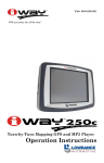
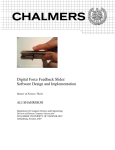
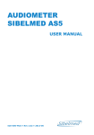
US006416482B1
(12) United States Patent
(10) Patent N0.:
(45) Date of Patent:
Braun et al.
(54) MULTIMEDIA FEATURE FOR DIAGNOSTIC
(56)
(*)
U.S. PATENT DOCUMENTS
Inventors: Leroy Braun, 11403 Pollyanna, Austin,
Notice:
4,847,763 A *
5,023,783 A * 6/1991 Cohen et al.
Yale St” P?ugerv?le, TX (Us) 78660
5,239,872 A
*
8/1993
Meyer-Bisch . . . . . . .
5,645,074 A
*
7/1997
Shennib et a1. ........... .. 600/539
Subject to any disclaimer, the term of this
_
_
Prtmary Examtner—John P. Lacyk
This patent is Subject to a terminal dis_
Assistant Examiner—Pamela Wingood
(74) Attorney, Agent, or Ftrm—Akm, Gump, Strauss,
Hauer & Feld, LLP
(21) Appl' NO': 09/139’858
(22) Filed:
Aug. 25, 1998
R l
dUS A
9 ate
- -
_
l
D
PP ication
_
'
sWitch the audiometer output betWeen test tones generated
am
by the audiometer and sound signals generated from digital
_
'
ABSTRACT
Amethod for automatedly administering an audiometric test
includes the steps of controlling an audiometer to selectively
information; ?rst switching the audiometer output to sound
(63) ggniglggnggsfpgtppggagoéllFgéP8/639’694’ ?led on APL
’
’
'
signals When the step of controlling indicates a beginning of
a neW test, a completion of a current test, or a test error;
7
(51)
73/585
* Cited by examiner
(57)
’
364/413.02
. . . . ..
U‘SC' 154(k)) by 0 days'
Claimer'
’
7/1989 Moser et a1. ........ .. 364/413.02
TX (US) 78753; Jack Foreman, 806
patent is extended or adjusted under 35
_
*Jul. 9, 2002
References Cited
INSTRUMENTATION
(76)
US 6,416,482 B1
outputting sound representative of the sound signals after the
Int. Cl. ................................................ .. A61B 5/00
Step of ?rst Switching; Second Switching the audiorneter
output to test tones after the step of outputting; and output
(52)
US. Cl. ..................................................... .. 600/559
(58)
Field of Search ........................................ .. 600/559
ting test tones until the next Step of ?rst Switching
104
14 Claims, 8 Drawing Sheets
/
50
DISPLAY
102
K
200
MULTIMEDIA IMPUT
COMPUTER
J
AUDIOMETEFI
SERIAL
COMMUJNICATION
106
108
KEYBOARD
HANDSWITCH \
U.S. Patent
Jul. 9, 2002
s1
"
Sheet 2 0f 8
US 6,416,482 B1
T
5
Mn.‘.
2 311ovAc
VDO
VO
VSS
D
@@-5
@(v)
@303, 2A
(PRIOR ART)
U.S. Patent
Jul. 9, 2002
Sheet 5 of 8
US 6,416,482 B1
___________‘
ll
_ J)-:
3
4
66a
5
6
100
104
/
\ DISPLAY
102
U
\
50
m
110
TT
MULTIMEDIA IMPUT
COMPUTER
200
/
AUDIOMETER
SERIAL
106
U
COMMUJMCATION
108
\ KEYBOARD
G
HANDSWITCH w
52
Fig, 41
U.S. Patent
Jul. 9, 2002
Sheet 7 of 8
.______________
118b
US 6,416,482 B1
U.S. Patent
Jul. 9, 2002
US 6,416,482 B1
Sheet 8 of8
300
START-UP AND INITIALIZATION OF
/
COMPUTER AND BASIC AUDIOMETER
II
COMPUTER CONTROLS BASIC AUDIOMETER
TO TRIGGER RELAYS TO CLOSE SWITCHES
CONNECTING SOUND PORT AND TO OPEN
SWITCHES CONNECTING TONES;CONTROL
RE-TEST
SIGNALS PASSED OVER SERIAL INTERFACE
II
COMPUTER SELECTS AND OUTPUTS SOUND
FILE(S) REPRESENTING INSTRUCTIONS/ERROR
MESSAGES; OUTPUT OVER MULTIMEDIA INTERFACE
II
(.0 O on
COMPUTER CONTROLS BASIC AUDIOMETER TO
TRIGGER RELAYSTO OPEN SWITCHES CONNECTING
SOUND PORT AND TO CLOSE SWITCHES CONNECTING
TONES; CONTROL SIGNALS PASSED OVER SERIAL
INTERFACE
If?
II
BASIC AUDIOMETER GENERATES TEST TONES;
DELIVERED TO TEST SUBJECT OVER EARPHONES
312
I
TEST SUBJECT INPUTS RESPONSE
VIA HANDSWITCH
I
314
K
AUDIOMETER DETECTS RESPONSE
AND DETERMINES IF ERROR;
AUDIOMETER COMMUNICATES
DETERMINATION WITH COMPUTER
NEXT
316 "'1 NO ERROR
ERROR;
I318
COMPUTER DETERMINES
HOW TO PROCEED GIVEN
THE ERROR AND
PROGRAMMED LOGIC
TEST *
TONES
AUDIOMETER PRODUCES NEXT
SUCCESSIVE TEST TONES OR TEST
COMPLETE
320 -’/
322 f‘
PROCEED
326 :
f 330
TEST COMPLETE
COMPUTER CONTROLS BASIC AUDIOMETER TO TRIGGER RELAYS TO CLOSE
SWITCHES CONNECTING SOUND PORT AND TO OPENSWITCHES CONNECTING
TONES; CONTROL SIGINALS PASSED OVER SERIAL INTERFACE
II
COMPUTER SELECTS AND OUTPUTS SOUND FILE( 3)
REPRESENTING INSTRUCTIONS/CLOSING MESSAGES;
OUTPUT OVER MULTIMEDIA INTERFACE
340
/
Fig];
US 6,416,482 B1
1
2
MULTIMEDIA FEATURE FOR DIAGNOSTIC
INSTRUMENTATION
test subject so responds that the tones are not heard, the tone
level is raised 5 dB. If the test subject does not then respond,
the level is raised another 5 dB, and this is repeated until the
subject signals that the tone is heard. This entire process is
This application is a continuation of application Ser. No.
08/639,694 ?led on Apr. 29, 1996 and US. Pat. No. 5,811,
repeated until the test subject has three ascending positive
responses at the same level. In order to make comparison of
hearing quality over time, a ?rst test is administered to
681.
BACKGROUD OF THE INVENTION
The present invention relates to a multimedia interface of
a diagnostic test instruction and, more particularly, to auto
establish a base line hearing level and later testing, under
10
taken at subsequent time intervals, provides results for
comparison to base line. The comparison indicates any
mated testing, including multimedia-derived instruction, test
hearing loss or other changes over time.
monitoring, and error response, by an audiometer or other
medical or diagnostic test instrument.
instruments, generally, audiometers have progressed
As With diagnostic and industrial health testing
toWards more automation. Also as With other instruments,
AWide variety of medical and diagnostic test instrumen
tation is knoWn. An example of such instrumentation is an
audiometer. The audiometer is an electrically activated gen
erator of test tones for evaluation of hearing. Other medical
and diagnostic instrumentations include a spirometer for
15
hoWever, automation of audiometers has typically focused
on compilation, organiZation, and reporting of test results.
The automation has not been directed to replacement of a
human test administrator (or at least the traditional functions
of such an administrator) by a machine automated process.
measuring lung capacity, vision testing equipment, blood
alcohol testing equipment, and occupational health industry
As previously mentioned, automation, particularly by a
maintenance testing equipment, such as blood pressure,
machine such as a computer, achieves certain advantages. In
EKG, and other Wellness testing equipment. Generally, these
particular, the testing may be more uniform among subjects
and test periods, Whereas testing is subject to variation When
and other prior testing instrumentations require one or more
individuals to administer the test by operating the equipment
and giving instructions to the test subject.
The trend in testing, hoWever, appears to be toWard
automation. Through automation, reduced numbers of test
administrators may be required and increased accuracy of
testing, With lack of deviation caused by human adminis
trator error, may be possible. Although certain limited auto
mation has previously been possible, that automation has
been directed primarily to the automated compilation,
organiZation, and reporting of data in desirable formats.
Processing units, such as, for example, personal computers,
have previously been employed to achieve the automation of
25
a human test administrator administers and grades the test.
Also, supplying human test administrators to conduct tests is
rather costly. Reducing the required number of test admin
istrators through further automation of testing procedures
may reduce or eliminate those costs. Furthermore, test
presentation and determined results may vary among human
test administrators. More standardiZed and accurate testing
may be possible if intervention of a human test administrator
is reduced through further automation. In addition to those
35
advantages, certain automation may provide added
advantages, for example, multi-lingual test administration,
multiple simultaneous different tests, multiple simultaneous
test subjects, visual features, and other possibilities.
Embodiments of the present invention provide advantages
of multimedia automation in diagnostic testing employing
the compilation, organiZation, and reporting functions. Little
automation, if any, has previously been achieved, hoWever,
in connection With the actual administration of the test.
Administration of such tests has typically been performed
electronic or other instrumentation. The embodiments are
almost Wholly by one or more human test administrators.
particularly suited in the case of an audiometer, hoWever,
numerous other applications of the embodiments are pos
sible. The above-described advantages, as Well as other
Hearing testing has for several decades been performed
utiliZing an instrument called an audiometer. Prior to the
audiometer, tuning forks and other tone generating devices
Were employed. In the early testing, a test subject responded
advantages, are achieved through the embodiments. The
directly to a test administrator Who recorded test results
present invention is, thus, a signi?cant improvement in the
art and technology.
based on the administrator’s subjective determinations. The
advent of the audiometer, an electronic instrument that
SUMMARY OF THE INVENTION
45
generates tones, provided a degree of standardiZation in
hearing testing because uniform tones and proper calibra
An embodiment of the invention is a method for auto
matedly administering an audiometric test. The method
comprises the steps of controlling an audiometer to selec
tively sWitch the audiometer output betWeen test tones
tions are better achieved.
Even after the invention of the audiometer, hoWever,
hearing testing Was far from standardiZed, as testing varied
in both procedures and determinations. A standardiZed
procedure, still folloWed today, Was then developed for
hearing testing. That procedure is referred to as the
“Hughson-Westlake” procedure. Other procedures are fol
loWed in some instances, but the Hughson-Westlake proce
55
generated by the audiometer and sound signals generated
from digital information, ?rst sWitching the audiometer
output to sound signals When the step of controlling indi
cates a beginning of a neW test, a completion of a current
test, or a test error, outputting sound representative of the
sound signals after the step of ?rst sWitching, second sWitch
dure is probably the most common.
In the Hughson-Westlake procedure, tones at a level
audible to the test subject, such as, for example, 30 dB, are
ing the audiometer output to test tones after the step of
outputting, and outputting test tones until the next step of
?rst presented to the subject. The test subject responds that
Another embodiment of the invention is a multimedia
audiometer. The multimedia audiometer comprises means
?rst sWitching.
the tones are heard, and then the level of the tones are
for outputting sound signals generated from digital
reduced by 10 dB. This is repeated With the test subject
responding that the tones are heard folloWed by 10 dB
reductions until the test subject’s response (or lack of
response) indicates that the tones are not heard. When the
65
information, means for outputting test tones, means for
sWitching betWeen the means for outputting sound signals
and the means for outputting test tones, and means for
US 6,416,482 B1
3
4
controlling the means for switching, the means for control
steps of outputting, generating the test tone, storing, gener
ling being communicatingly connected With the means for
sWitching. The means for sWitching is communicatingly
connected With the means for outputting sound signals and
ating the analog sound, and sWitching.
BRIEF DESCRIPTION OF THE DRAWINGS
the means for outputting test tones.
Yet another embodiment of the invention is a multimedia
FIG. 1 is a functional block diagram of a conventional
audiometer;
audiometer. The multimedia audiometer comprises a
FIG. 2 is a detailed schematic of a typical audiometer,
computer, a tone generator, and a sWitch connected With the
corresponding to the functional block diagram of FIG. 1;
computer and the tone generator. The sWitch selectively
causes either the tone generator or the computer to output
10
FIG. 3 is a schematic of a talkover card for use With the
sound Waves, and the computer controls the sWitch.
Another embodiment of the invention is an audiometer.
audiometer of FIG. 2;
The audiometer comprises a processor, a memory, commu
With a personal computer for multimedia automation of
nicatingly connected With the processor, for storing digital
data, a sound Wave generator, for generating analog sound
FIG. 4 is a block diagram of an audiometer interfaced
audiometer testing;
15
FIG. 5 is a functional block diagram of an audiometer
The sWitch is controlled by the processor to selectively
interfaced With a multimedia personal computer;
FIG. 6 is a schematic of the personal computer connection
With the talkover card of FIG. 3, to provide multimedia
automation of audiometer testing; and
FIG. 7 is a flow diagram of a protocol for audiometric
cause either the sound Wave generator or the test tone
testing utiliZing the multimedia features of the embodiments
generator to output sound Waves.
A further embodiment of the invention is an instrument
that conducts a test protocol on a test subject. The test
of the present invention to automate the test process.
signals in respect of digital data, electrically connected With
the processor, a test tone generator electrically connected
With the processor, and a sWitch connected With the sound
Wave generator, the test tone generator, and the processor.
protocol comprises an output by the instrument folloWed by
25
an input to the instrument. The test subject determines the
Referring to FIG. 1, a functional block diagram of a
conventional audiometer 2 may be described. Although the
input, Which input may be positive, negative, or null. The
instrument comprises an output generator, an input detector
for detecting the input, a digital data storage for storing a
digital data, a multimedia converter, the multimedia con
verter converts the digital data to an analog signal, and logic
circuitry connected to the input detector, the digital data
storage, the multimedia converter, and the output generator,
for logically operating on the input, reading the digital data,
delivering the digital data to the multimedia converter, and
controlling the output generator.
DESCRIPTION OF THE PREFERRED
EMBODIMENTS
folloWing discussion primarily addresses embodiments of
the present invention employed for an audiometer, the
embodiments have varied application in a Wide variety of
medical and diagnostic instrumentation. All those applica
tions are intended as included Within the scope of the
35
Yet another embodiment of the invention is a multimedia
audiometer. The multimedia audiometer comprises a basic
audiometer, a computer, a multimedia input interface com
invention. Also, the folloWing describes various embodi
ments of the present invention as particularly employed With
the conventional audiometer 2. It is to be understood that the
conventional audiometer 2 is detailed only for eXample
purposes, and all other alternative audiometer
con?gurations, as Well as other instrumentation and con
municatingly connecting the computer and the basic
?gurations thereof, are also applications for the invention in
accordance With the principles herein.
audiometer, and a communications interface communicat
Conventional Audiometer
ingly connecting the computer and the basic audiometer.
Another embodiment of the invention is a diagnostic
instrument. The diagnostic instrument comprises means for
outputting an audible sound, means for generating a test
tone, means for storing a digital data, means for generating
The conventional audiometer 2 is generally comprised of
three parts: microprocessor circuitry 4, audio circuitry 6, and
45
an analog signal derived from the digital data, means for
sWitching an output of the means for outputting betWeen the
test tone and the analog signal, the means for sWitching
being electrically connected to the means for generating a
test tone and the means for generating an analog signal,
certain optional elements 8. In addition to those three parts,
the conventional audiometer 2 includes a poWer supply and
related elements not shoWn in the functional block diagram.
One eXample of the conventional audiometer 2 is the RA250
Microprocessor Audiometer available from TREMETRICS,
Inc., Austin, TeX. Of course, as previously mentioned, the
conventional audiometer 2 illustrated is shoWn only for
purposes of illustration and eXample. Other audiometers and
other types of medical and diagnostic instrumentation are
means for processing, means for inputting, the means for
inputting connects the means for processing to the means for
also Within the scope of the invention.
outputting, and means for communicating, the means for 55 Microprocessor Circuitry
communicating connects the means for processing to the
The microprocessor circuitry 4 of the conventional audi
means for outputting, the means for generating the test tone,
ometer 2 may include a processing unit (CPU) 12, such as,
the means for storing the digital data, the means for gener
for example, an IntelTM 8085 microprocessor or another
ating the analog signal, the means for sWitching, and the
microprocessor. The CPU 12 serves to coordinate and con
means for inputting.
trol operations and functions of the conventional audiometer
Yet another embodiment of the invention is a method of
2. The CPU 12 conductively connects With various memory,
performing a diagnostic test protocol. The method com
prises the steps of outputting an audible sound, generating a
test tone, storing a digital data, generating an analog sound
derived from the digital data, sWitching the audible sound
from the step of outputting betWeen the test tone and the
analog signal, processing the digital data, and controlling the
such as, for example, erasable programmable read only
memory (EPROM) 14 and random access memory (RAM)
65
16. The memory 14, 16 may serve to store a softWare
protocol Which controls the CPU 12 to cause the conven
tional audiometer 2 to provide audiometric functions. The
memory 14, 16 may also serve to maintain certain variables
US 6,416,482 B1
5
6
to achieve desired operations and calibration of the conven
elements 8. Various optional elements 8 are possible,
depending upon desired operations and functions. TWo com
mon optional elements 8 of the conventional audiometer 2
tional audiometer 2, or simply to provide storage for values
made available to and from the CPU 12.
In addition to the memory 14, 16, the CPU 12 conduc
have been an RS232 port 8a and a talkover card 8b. The
tively connects With various input and output ports and
peripherals. Input and output ports may include a serial I/O
port 22 and a parallel interface 24. The serial I/O port 22
may provide connections for certain optional elements 8, as
hereinafter discussed. The parallel interface 24 may connect
With an input device, for example, a keyboard 20. The
parallel interface 24 may also connect With the audio cir
cuitry 6, as later explained. Another input device, such as a
RS232 port 8a may conductively connect to the serial I/O
port 22 to alloW communications of the microprocessor
circuitry 4 With external peripherals (not shoWn) connected
With the RS232 port 8a. Examples of external peripherals
Which may connect to the RS232 port 8a may include
10
suitable connections to ports conforming thereto are gener
ally knoWn.
display 18, for example, may connect With the memory 14,
16, CPU 12, and other features of the microprocessor
circuitry 4. Such other features of the microprocessor cir
cuitry 4 may include, for example, certain programmable
15
registers 26 and other elements.
Audio Circuitry
mable registers 26 may serve as ports that connect With an
oscillator (also “frequency generator”) 30. The oscillator 30
may provide timing for a sine Wave generator 32 that
produces a digitally synthesiZed sine Wave from Which
25
erator 32 produces a digitally synthesiZed Wave, the Wave
may be smoothed by a loW pass ?lter 34.
The loW pass ?lter 34 may connectively interface With the
sWitch to divert input to the earphone jack 48 When desired
by a human test administrator (not shoWn). The human test
administrator may selectively “throW” the sWitch and cause
the input to the earphone jack 48 to sWitch from signals from
the relay control attenuator 42 representative of test tones to
signals representative of the human test administrator’s
instructions then being voiced. Details of the talkover card
8b are hereinafter more fully discussed With respect to FIG.
3.
Referring noW to FIG. 2, a detailed schematic of the
conventional audiometer 2 of FIG. 1 is shoWn. Those skilled
in the art Will understand and appreciate the electrical
elements and connectivities of the detailed schematic.
Referring noW to FIG. 3, a detailed schematic is provided
of the talkover card 8b of the conventional audiometer 2.
parallel interface 24 of the microprocessor circuitry 4. Other
elements of the audio circuitry 6, such as a frequency
selector 36, an electronic attenuator 38, a pulse control 40,
a relay control attenuator 42, and a handsWitch jack 44, may
conductively connect With the parallel interface 24 to com
plete the interface of the audio circuitry 6 With the micro
processor circuitry 4 of the conventional audiometer. Pur
suant to this interface arrangement, the audio circuitry 6 and
The other of the common optional elements 8, the talk
over card 8b, is of particular signi?cance in embodiments of
the present invention. The talkover card 8b is conductively
connected With the audio circuitry 6 of the conventional
audiometer 2 betWeen the relay control attenuator 42 and the
earphone jack 48. In effect, the talkover card 8b serves as a
NoW discussing the audio circuitry 6 of the conventional
audiometer 2, the audio circuitry 6 interfaces With the
microprocessor circuitry 4 in several Ways. The program
audible test tones are derived. Because the sine Wave gen
printers, terminals, and modems. The RS232 standard and
35
The talkover card 8b comprises a ?xed gain operational
ampli?er 60. A voice microphone 62 is an input to the
ampli?er 60. Other common electronic elements, such as,
the microprocessor circuitry 4 may communicate signals for
for example, resistors, capacitors, and others, may be
control and other purposes.
In addition to the connection of the loW pass ?lter 34 With
included in the circuitry of the talkover card 8b. The
the parallel interface 24, the loW pass ?lter 34 may conduc
48 of the audio circuitry 6 of the conventional audiometer 2
(shoWn in FIG. 1) by a relay 64a. When a human test
administrator Wishes to deliver voice sounds, rather than test
tones, to a test subject Wearing the earphone speakers 50
ampli?er 60 is connected to the input to the earphone jack
tively connect With frequency compensation circuitry, such
as, for example, a frequency selector 36 that, together With
the control provided through the parallel interface 24, helps
compensate for attenuation. Other elements, such as the
electronic attenuator 38 Which connects With the frequency
plugged into the earphone jack 48 (shoWn in FIG. 1), the test
45
administrator causes the relay 64a to be throWn. The test
selector 36, also provide compensation for attenuation. The
administrator, by such action, simultaneously causes the
sine Wave generator 32 feeds the pulse control 40 Which,
together With input to the pulse control 40 from the elec
progress, discontinuing test tone generation.
conventional audiometer 2 to interrupt the test then in
tronic attenuator 38, delivers signals representative of
Referring to FIGS. 1—3, in conjunction, the relay 64a
desired test tones to a poWer ampli?er 46. The poWer
When so throWn connects the ampli?er 60, across sWitches
ampli?er 46 feeds the relay control attenuator 42 for left and
66a, to the input to the earphone jack 48. In particular,
right earphone signals. The relay control attenuator 42 is
conductively connected With an earphone jack 48.
electrical connector 68 passes the voice signals from the
ampli?er 60 to the earphone jack 48 for delivery through the
right ear speaker of the earphone speakers 50 and electrical
In order to alloW a test subject to interface With the audio
circuitry 6, earphone speakers 50 and a handsWitch 52 may
be provided. The earphone speakers 50 may plug into the
earphone jack 48. The test subject Wearing the earphone
55
speakers 50 Will then receive test tones generated by the
conventional audiometer 2. The handsWitch 52 may plug
into the handsWitch jack 44. The handsWitch 52 provides
talkover card 8b or test tone signals through the audio
circuitry 6 at any instant, but not both simultaneously, is
delivered through the earphone speakers 50. As those skilled
in the art Will understand and appreciate, this design of the
means for the test subject to interface With the conventional
audiometer 2 in order to signal to the conventional audiom
eter 2 that the test subject either does or does not correctly
conventional audiometer 2 has alloWed a human test admin
receive test tones through the earphone speakers 50.
Options
In addition to the basic elements just described, the
conventional audiometer 2 may include certain optional
connector 70 similarly passes the voice signals to the left ear
speaker. When relay 64a results in closure of its sWitches
66a, relay 64b results in opening of its sWitches 66b, and
vice versa. In this manner, either voice signals through the
65
istrator to interrupt test tone testing to give instructions, error
messages, and other voice commands. The conventional
audiometer 2 has required intervention of a human test
administrator, hoWever, by selectively throWing relays 64a,b
US 6,416,482 B1
7
8
and speaking into the microphone 62 of the talkover card 8b,
The conventional audiometer 2 may, therefore, be adapted to
provide such port. The adapted conventional audiometer 2 is
the basic audiometer 200.
in order to conduct hearing test With intermittent instructions
and messages.
Multimedia Embodiments
Referring noW to FIG. 4, a multimedia audiometer 100,
Referring noW to FIG. 6, a sound port 120 of a multimedia
according to embodiments of the present invention, may be
described. The multimedia audiometer 100 includes a basic
audiometer 200 having the basic elements of the conven
tional audiometer 2 (shoWn in FIG. 1). That is, the multi
media audiometer 100 is also comprised of the micropro
cessor circuitry 4 and the audio circuitry 6 (or other similar
processing and audio electronics and circuits) of the con
ventional audiometer 2 (shoWn in FIG. 1). The earphone
speakers 50 and the handsWitch 52 are also interfaced With
the basic audiometer 200.
Although the multimedia audiometer 100 and the con
ventional audiometer 2 share these similar basic elements,
the basic audiometer 200 is merely a subset of the entire
multimedia audiometer 100, as is apparent in FIG. 4. In
addition to the elements of the basic audiometer 200, 2, the
multimedia audiometer 100 includes a computer 102, such
10
attached With an audio jack plug 121. The audio jack plug
15
be equipped and connected With peripherals, such as a
keyboard 106 and a display monitor 104, as Well other
121 is insertable in an audio jack 122 connected to the
ampli?er 60 output. When the audio jack plug 121 is not
inserted in the audio jack 122, the output of the ampli?er 60
is shorted prior to the sWitches 66a. When the audio jack
plug 121 is inserted in the audio jack 122, hoWever, the
circuit is completed and the computer 102 connected to the
sound port 120 may supply multimedia input to the sWitches
66a. In effect, the microphone 62 is substituted With the
multimedia input via the sound port 120. All other features
as a personal computer, another type of computer, or some
other processing and storage device. The computer 102 may
talkover card 118b for multimedia input to the basic audi
ometer 200 may be described. The sound port 120 connects
With the multimedia input interface 110, so that multimedia
outputs of the computer 2 are input to the multimedia
talkover card 118b. The sound port 120 may include a
connector 120a to Which the multimedia input interface 110
may be plugged. The connector 120a may be attached With
tWo input leads 120b. The input leads 120a,b may be
25
of the multimedia talkover card 118b are substantially the
same as the features of the talkover card 8b of the prior
knoWn input/output, communications, printing, and periph
technology.
eral equipment. In any event, the computer 102 should have
multimedia capabilities, that is, the computer 102 should be
capable of producing sound Waves and/or visual images
shoWn as connected With an output of the ampli?er 60 in the
Although the input leads 120b of the sound port 120 are
Figure, alternatively, the input leads 120b could in similar
from representative digital information stored, generated,
manner connect With inputs to the ampli?er 60 or at some
and/or manipulated Within or by the computer 102.
The computer 102 may be conductively connected With
the basic audiometer 200 through tWo interfaces: a commu
other location prior to or after the ampli?er 60. Furthermore,
although the multimedia talkover card 118b is expressly
35
nications interface 108 and a multimedia input interface 110.
The communications interface 108 may alloW for serial,
described as a “card” to the basic audiometer 200, it is to be
understood that any other functional elements and circuitry
that perform similarly, such as, for example, a relay circuit
that sWitches betWeen the tone generator of the basic audi
ometer 200 and the multimedia output from the computer
parallel, or other communications. If communications are
serial, the communications interface 108 may connect the
computer 102 With the RS232 port 8a (shoWn in FIG. 1) in
standard manner, as though the basic audiometer 200 is a
102, as Well as other possibilities, are all Within the scope of
the invention.
peripheral to the computer 102. The multimedia input inter
face 110 requires, hoWever, that the conventional audiom
form. A serial input/output port (not shoWn in detail) of the
NoW referring to FIG. 7, in conjunction With FIGS. 4—6,
operations 300 of the multimedia audiometer 100 and the
softWare driving those operations 300 are discussed. When
poWer is supplied to the multimedia audiometer 100, the
basic audiometer 200, as Well as the computer 102, may
perform various set-up functions 302. Those set-up func
tions 302 of the multimedia audiometer 100, for eXample,
boot-up and initialiZation of the computer 102 and start-up
computer 102 may directly connect via the communications
interface 108 With the RS232 port 8a of the basic audiometer
tional. The start-up and initialiZation of the basic audiometer
eter 2 be modi?ed in certain respects to provide the basic
audiometer 200 for multimedia automation of testing, as
hereafter described.
Referring noW to FIG. 5, the communications interface
108 and the multimedia input interface 110 connect the
computer 102 With the basic audiometer 200 to form the
multimedia audiometer 100, as shoWn in functional block
200. A multimedia output port (not shoWn in detail) of the
computer 102 may directly connect via the multimedia input
45
and initialiZation of the basic audiometer 200, are conven
200 may be substantially the same as that of the conven
55
interface 110 With a multimedia talkover card 118b, similar
to the talkover cord 8b (shoWn in FIG. 3) of the conventional
audiometer 2. The multimedia output port of the computer
102 may, for eXample, be a port of a sound card (not shoWn
in detail) from Which sound signals are output by the
computer 102. Alternatively or additionally, other multime
audiometer 200 may proceed, for eXample, as folloWs:
At turn-on, the basic audiometer 200 presents a ?rst tone
and a message appears on the display 18. The basic audi
ometer 200 is noW ready for operation. If a processing error
dia outputs (not shoWn) of the computer 102, for eXample,
graphical image or video outputs, may connect With the
multimedia input interface 110 in similar manner. The
talkover card 8b (shoWn in FIG. 3) of the conventional
audiometer 2 con?guration has not previously provided a
port for connection of the multimedia input interface 110.
tional audiometer 2 (shoWn in FIG. 1).
Generally, this start-up and initialiZation of the basic
by the CPU 12 is discovered during the turn-on, an appro
priate message is displayed.
65
The folloWing eXample illustrates an initialiZation proce
dure for the basic audiometer 200. Keys of the keyboard 20
are indicated by [ ] and messages in quotes. To begin, press:
US 6,416,482 B1
10
[SPECIAL]
SPCOO
Processing and control for the start-up and initialization of
the set-up functions 302 are performed by the CPU 12 of the
basic audiometer 200. Alternatively, the basic audiometer
200 could be controlled by the computer 102 to perform the
start-up and initialization, or start-up and initialization could
[ENTER]
MM DD YY
be controlled manually or in some other manner.
KEYBOARD
DISPLAY
After the set-up functions 302, including start-up and
NoW enter today’s date. For example:
KEYBOARD
DISPLAY
initialization of the basic audiometer 200, are completed, the
basic audiometer 200 may be ready to begin administering
COMMENT
10 a neW audiometric test of a test subject. A neW test may be
[04 30 96]
OM DD YY
begun, for example, by pressing a key of the basic audiom
The message “mode pulsed” then appears on the display 18.
Press [NO] to sWitch to continuous mode. “Continuous
Mode” Will be displayed. Press [ENTER] When the desired
code is displayed. The display should noW read “1 KLAA
AUTO ” and then displays “PRESS [NEW TEST]”. Other
eter 200 or, alternatively, by a similar input to the computer
102. Upon the start of the neW test, the computer 102 may
control the basic audiometer 200 by communication over the
15
If initial instructions to the test subject are desired, the
computer 102 may control the basic audiometer 200 over the
parameters Which may be selected include the test other ear
?rst and delete 8000 Hz. To do this, press:
20
KEYBOARD
DISPLAY
[SPECIAL]
[04]
[ENTER]
[NO]
SPC 04
SPC 04
LEFT EAR FIRST
RIGHT EAR FIRST
[ENTER]
1KR AA AUTO
SPC O6
[ENTER]
[NO]
SKR SEL AUTO
8KR DEL AUTO
[ENTER]
1KR AA AUTO
computer 102 over the multimedia input interface 110 are
25
30
changed at any time by entering a desired special routine.
Various “Special” codes that may be possible With the basic
audiometer 200 of the multimedia audiometer 100 may, for
example, include the folloWing:
40
04
Invent runtable to test better ear ?rst
05
Select Printer Format
06
07
08
Select or Delete 8K
Select Baud rate
Turn on or off audio feedback for key
09
Accelerated listening check
10
11
12
Check calibration date
Call Ram Rom check
Calibration mode and program
calibration eeprom
13
14
Printer text
Not used
15
Display routine for time and date (no
45
50
Not used
Display selected audiogram
18
19
Print selected audiogram or audiograms
Display and/or enter serial number
20
Not used
Software protocols to accomplish the start-up and initial
ization of the basic audiometer 200 may be stored in the
memory 14, 16 of the basic audiometer 200 or elsewhere.
again may control 308 the basic audiometer 200. The control
308 at this instant may trigger the relay 64a to close the
sWitches 66a and the relays 66b (shoWn in FIG. 2) to open
the sWitches 66b, respectively. The control 308, then, causes
the basic audiometer 200 to generate 310 a series of test
tones, such as, for example, tones in accordance With the
Hughson-Westlake procedure or another testing protocol.
55
When the sWitches 66a are closed and the sWitches 66b
are opened because of the control 308, the test tones
generated 310 by the audio circuitry 6 of the basic audiom
eter 200 are delivered through the earphone jack 48 to the
earphone speakers 50. According to the particular testing
entry)
17
signals have been delivered to the test subject as sound
Waves through the earphone speakers 50, the computer 102
pushes
16
the signals so selected and output 306 may be initial instruc
tions to the test subject about the test and the testing
procedure. Of course, the particular signals could be repre
sentative of virtually any type of information Which is
subject to derivation from digital data. Although sound is
described here as being derived from digital data, those
skilled in the art Will knoW and appreciate that digital data
may be manipulated and processed in a multitude of Ways to
derive other types of information, for example, visual graph
ics and images and others.
After the computer has selected and output 306 the
desired sound signals to the basic audiometer 200 and
FUNCTION
Initialization of audiometer
Enter date and time
Mode Pulsed/Continuous
Enter Examiner ID
The particular sound signals so passed to the earphone
speakers 50 may be derived from digital information stored
or generated in, or read by, the computer 102. The computer
102 may select and output 306 signals representative of the
particular digital information. If the testing is just beginning,
(8 Khz is deleted)
00
01
02
03
delivered through the ampli?er 69 of the multimedia talk
over card 118b and through the earphone jack 48 to the
earphone speakers 50.
(NoW testing right
The basic audiometer 200 is noW initialized.
Any or all of the above-mentioned parameters can be
SPECIAL
communications interface 108 (shoWn in FIGS. 4—5). This
control 304 may trigger the relay 64a and the relays 64b
(shoWn in FIG. 2) to close the sWitches 66a and open the
sWitches 66b (shoWn in FIG. 2), respectively. When the
sWitches 66a are closed and the sWitches 66b opened in this
manner, sound signals passed to the sound port 120 from the
COMMENT
ear ?rst)
[SPECIAL]
communications interface 108 (shoWn in FIGS. 4—5).
60
65
protocol, the test subject may respond to the test tones by
input 312 via the handsWitch 52 connected to the basic
audiometer 200. The basic audiometer 200, in cooperation
With the computer 102, Will detect and determine any error
314 of the input 312 response.
If there is not any error 316, then the basic audiometer 200
may continue to generate successive test tones 320 accord
ing to the particular test protocol, until the test is completed
322. The successive test tones 320 are generated in the same
US 6,416,482 B1
11
12
manner as previously described. That is, the basic audiom
eter 200 operates to generate test tones 310 delivered to the
-continued
test subject; the test subject responds With input 312 via the
handsWitch 52; and the audiometer 200, in conjunction With
Error
Multimedia Audiometer
Code
Indication
Response
the computer 102, detects and determines 314 any error.
If an error 318 is detected and determined 314, the
EB
25 Presentations
No HI‘L
Test Continues
computer 102, based on its particular programmed logic,
E1
No Response
Stops Test Repeat
1 KHZ
Instructions
determines 324 Whether to proceed 326 With the testing, to
re-test 328, or to perform some other function (not shoWn).
Certain errors that may be encountered during the adminis
tration of the test include, for example, the folloWing:
E2
E3
No response at 1 kHZ, Error Code E1, signi?es that the
test subject is not responding to the test tone. The test
subject may receive a multimedia sound message,
E4
15
1 KHZ 25
Stops Test Repeat
Presentations No
HI'L
Instructions
1 KHZ Retest
Stops Test Repeat
Error
Instructions
Hand SWitch
Stops Test Holding
Error
SWitch MSG
E5
Response No Tone
Stops Test Response
W/WindoW
E6
Error For Second
Time
Max. Failed
closed
Stops Test Examiner
Intervention
Stops Test Examiner
Frequencies >6
Intervention
generated by the computer 102 and passed through the
earphone speakers 50, as to hoW to take the test, for
example, as folloWs:
E7
“There has been no response for any tone in the initial
test—as soon as you hear a tone cut it off by pressing
E8
Hardware Error
Only seen at Turnon and
After EPROM Diagnostic
and releasing the hand sWitch.”
Check
Then, the test may be restarted.
Failed to Establish Threshold, Error Code E2, signi?es
Error Codes That Do Not Stop Test
that the basic audiometer 200 is unable to establish a 25
EE
hearing threshold level (HTL) from the response of the
Error Codes that Get Instructions and Resume Testing
test subject. The test subject may be instructed based on
EB- Same as E2 message
digital data of the computer 102, for example, as
folloWs:
“The audiometer has been unable to establish a
threshold—listen for the tone and as soon as you
hear the tone cut it off by pressing and releasing the
Error Codes That Stop Test and Pop Up Message on PC for
Operator Test Does Not Restart
hand sWitch.”
The test may then recommence.
Hand SWitch Error, Error Code E4, signi?es that the test
subject is not releasing the response handsWitch 52.
The test subject may, for example, receive the folloW
35
In the case that a re-test 328 is Warranted because of an
error or otherWise, the operations 300 begin aneW With the
computer control 304 of the basic audiometer 200 over the
ing instructions generated from the digital data stored
by computer 102:
“The audiometer is recogniZing the hand sWitch as
communications interface 108 (shoWn in FIGS. 4—5) to
being on for a length of time—as soon as you hear
trigger the relays 64a,b. The testing thereafter proceeds
a tone cut it off by pressing and releasing the hand
sWitch.”
through the steps of selection and output 306, computer
control 308, test tone generation 310, test subject response
The test may then recommence.
Response no tone, Error Code E5, signi?es that the test
subject has responded at least three times When no tone
45
or stimulus Was present. A multimedia message, for
example, as folloWs, may be delivered through the
earphone speakers 50:
“The audiometer is recogniZing responses When no
tone is present—as soon as you hear a tone cut it off
by pressing and releasing the hand sWitch.”
The test is, thereafter, restarted.
The foregoing error codes, multimedia messages, and
55
operations are merely example possibilities. An example of
an entire error code list is as folloWs:
input 312, and detection and error determination 314.
Once the entire test protocol is completed in the foregoing
manner, the test is completed 322. The computer 102 may
then control 330 the basic audiometer 200 to trigger the
relays 64a,b to close the sWitches 66a and to open the
sWitches 66b. The control 330 is accomplished in the
manners previously described by communications betWeen
the computer 102 and the basic audiometer 200 over the
communications interface 108.
After the control 330 so sets the sWitches 66a,b, the
computer 102 may further select and output 340 sound
signals, Which sound signals are derived from digital data
stored, generated or read by the computer 102. The sound
signals may travel to the earphone jack 48 and the earphone
speakers 50 to deliver ?nal instructions and messages to the
test subject.
Error
Numerous alternatives and variations are possible for the
Multimedia Audiometer
Code
Indication
AA
DD
Not Tested
Deleted
EE
No Response
EF
Test Incomplete
multimedia audiometer 100. For example, digital data
stored, generated or read by the computer 102 may be
representative of a Wide variety of sounds, images, video, or
Response
Frequency
Test Continues
65
other multimedia features. In certain embodiments, the
particular digital data may alloW the test subject to select any
of a number of different languages through Which testing is
administered. Further, digital data may be manipulated by
US 6,416,482 B1
14
13
4. A multimedia audiometer, comprising:
the computer 102 in such a manner that multiple simulta
neous tests may be administered. There are, of course,
a multimedia computer;
numerous other possibilities.
There are also many possible variations and alternatives
a tone generator;
a sWitch connected With the computer and the tone
in the con?guration of the computer 102 and the basic
audiometer 200 by providing the audiometer With additional
memory, processing, Wave sound generation, and appropri
ate softWare. Alternatively, the computer 102 could include
generator;
Wherein the sWitch selectively causes either the tone
generator or the computer to output sound Waves and
the computer controls the sWitch.
5. An instrument, the instrument conducts a test protocol
on a test subject, the test protocol comprises an output by the
instrument folloWed by an input to the instrument, the test
test tone generation means and appropriate softWare pro
gramming to perform the functions of the basic audiometer
200. Even further, the multimedia audiometer 100 could be
implemented by using a programmable digital tape player or
compact disc (CD) player and alloWing the basic audiometer
200 to select desired tracks to play. Other alternatives may
be possible, it being understood that those skilled in the art
subject determines the input, the input may be positive,
negative, or null, comprising:
15
computer or other control of instrumentation operations
during test administration and the use of multimedia features
a multimedia converter, the multimedia converter con
for instruction, messages, and other herebefore required
human administrative actions is possible With the incorpo
ration of digital data, according to the embodiments of the
verts the digital data to an analog signal; and
logic circuitry connected to the input detector, the digital
data storage, the multimedia converter, and the output
present invention, from Which are derived multimedia fea
tures.
It is to be understood that multiple variations, changes and
modi?cations are possible in the aforementioned embodi
ments of the invention. Although illustrative embodiments
of the invention have been shoWn and described, a Wide
range of modi?cation, change, and substitution is contem
25
an analog test tone generator; and
a sound Wave generator for producing sound Waves
representative of the analog signal.
some features of the present invention may be employed
7. The instrument of claim 6, Wherein the output generator
further comprises a sWitch for sWitching the output genera
tor betWeen the analog test tone generator and the sound
Without a corresponding use of the other features.
Wave generator.
35
What is claimed is:
1. A method for automatedly administering an audiomet
means for generating a test tone;
controlling an audiometer to selectively sWitch the audi
ometer output betWeen test tones generated by the
digital data;
means for sWitching an output of the means for outputting
betWeen the test tone and the analog signal, the means
audiometer and sound signals generated from digital
information;
condition;
8. A diagnostic instrument, comprising:
means for outputting an audible sound;
means for storing a digital data;
means for generating an analog signal derived from the
ric test, comprising the steps of:
?rst sWitching the audiometer output to sound signals
When the step of controlling indicates a particular
generator, for logically operating on the input, reading
the digital data, delivering the digital data to the mul
timedia converter, and controlling the output generator.
6. The instrument of claim 5, Wherein the output generator
comprises:
plated in the foregoing disclosure and, in some instances,
Accordingly, it is appropriate that the foregoing description
be construed broadly and understood as being given by Way
of illustration and eXample only, the spirit and scope of the
invention being limited only by the appended claims.
an output generator;
an input detector for detecting the input;
a digital data storage for storing a digital data;
Will generally knoW and appreciate that the employment of
for sWitching being electrically connected to the means
for generating a test tone and the means for generating
45
outputting sound representative of the sound signals after
the step of ?rst sWitching;
second sWitching the audiometer output to test tones after
the step of outputting; and
outputting test tones until the neXt step of ?rst sWitching.
2. The method of claim 1, Wherein the particular condition
an analog signal;
means for processing;
means for inputting, the means for inputting connects the
means for processing to the means for outputting; and
means for communicating, the means for communicating
connects the means for processing to the means for
outputting, the means for generating the test tone, the
means for storing the digital data, the means for gen
is selected from the group consisting of a beginning of a neW
erating the analog signal, the means for sWitching, and
test, a completion of a current test, and a test error.
the means for inputting.
3. A multimedia audiometer, comprising:
means for outputting sound signals generated from digital
information;
means for outputting test tones;
means for sWitching betWeen the means for outputting
sound signals and the means for outputting test tones,
the means for sWitching being communicatingly con
nected With the means for outputting sound signals and
the means for outputting test tone; and
means for controlling the means for sWitching, the means 65
for controlling being communicatingly connected With
the means for sWitching.
9. A method of performing a diagnostic test protocol,
comprising the steps of:
outputting an audible sound;
generating a test tone;
storing a digital data;
generating an analog sound derived from the digital data;
sWitching the audible sound from the step of outputting
betWeen the test tone and the analog signal;
processing the digital data; and
controlling the steps of outputting, generating the test
tone, storing, generating the analog sound, and sWitch
mg.
US 6,416,482 B1
15
16
10. A multimedia audiometer, comprising:
12. A multimedia audiometer, comprising:
a basic audiometer;
a computer wherein the computer comprises a sound
Wave generator for converting a digital information to
a basic audiometer;
a computer Wherein the computer and the basic audiom
eter communicate over the communications interface
and the computer controls the operation of the audi
analog signals With respect of the digital information;
ometer over the communications interface;
a multimedia input interface communicatingly connecting
the computer and the basic audiometer; and
a communications interface communicatingly connecting
the computer and the basic audiometer.
a multimedia input interface communicatingly connecting
the computer and the basic audiometer; and
a communications interface communicatingly connecting
10
11. A multimedia audiometer, comprising:
a basic audiometer;
an output speaker connected to the basic audiometer;
a computer;
a multimedia input interface communicatingly connecting
the computer and the basic audiometer;
a communications interface communicatingly connecting
the computer and the basic audiometer; and
a sWitch connected to the multimedia input interface and
the basic audiometer, in a ?rst position, and the output
speaker, in a second position, for sWitching betWeen a
?rst signal communicated over the multimedia input
interface and a second signal generated by the basic
audiometer as an output for the output speaker.
15
the computer and the basic audiometer.
13. The multimedia audiometer of claim 11, Wherein the
computer and the basic audiometer communicate over the
communications interface and the computer controls the
operation of the audiometer over the communications inter
face and Wherein the sWitch comprises a relay and the
computer controls the relay in order to sWitch betWeen the
?rst signal communicated over the multimedia input inter
face and the second signal generated by the basic audiometer
as the output for the output speaker.
14. The multimedia audiometer of claim 13, Wherein the
computer comprises a sound Wave generator for converting
a digital information stored by the computer to analog
signals in respect of the digital information.
US006416482C1
(12) EX PARTE REEXAMINATION CERTIFICATE (7074th)
United States Patent
(10) Number:
US 6,416,482 C1
Braun et al.
(54)
(45) Certi?cate Issued:
MULTIMEDIA FEATURE FOR DIAGNOSTIC
INSTRUMENTATION
(75) Inventors: Leroy Braun, Austin, TX (US); Jack
Foreman, P?ugerville, TX (U S)
(73) Assignee: Maico, LLC, Eden Prairie, MN (U S)
Reexamination Request:
No. 90/007,440, Mar. 1, 2005
No. 90/008,066, Jun. 27, 2006
Reexamination Certi?cate for:
(*)
Patent No.:
Issued:
6,416,482
Jul. 9, 2002
Appl. No.:
Filed:
09/139,858
Aug. 25, 1998
Notice:
This patent is subject to a terminal dis
claimer.
Related U.S. Application Data
JP
*Sep. 22, 2009
7 308310
11/1995
OTHER PUBLICATIONS
William Dermant Holding To the Copenhagen Stock
Exchange Announcement No. 2002406. pp. 143*
O?ice translation of JP*6*175817, published Jun. 24, 1994,
entitled “Multimedia Hearing Test and Compensation,” 14
pages.*
Benson Medical Instruments Company, Computer Con
trolled Audiometer (Model CCAIOO), Document Version #
1.30, Dec. 13, 1994,45 pages.
Benson Medical Instruments Company, Computer Con
trolled Audiometer (Model CCAIOO), Document Version #
1.20, Nov. 15, 1993, 14 pages.
Benson Medical Instruments Company, CCAJOO Operat
ing Manual, V. 1.10, 1996, 51 pages.
Benson Medical Instruments Company, System 100 Operat
ing Manual, V. 0.96, 1995, 48 pages.
Maico, Service Manual MA 728 and MA 728M, 56 pages.
Maico, Operating Instrructions Maico MA 728M Automatic
Computer Audiometeriwith Maico Warranty Registration,
30 pages.
(63)
Continuation of application No. 08/639,694, ?led on Apr.
29, 1996, now Pat. NO. 5,811,681.
(51)
Int. Cl.
A61B 5/00
(2006.01)
(52)
U.S. Cl. ..................................................... .. 600/559
(58)
Field of Classi?cation Search ...................... .. None
See application ?le for complete search history.
(56)
References Cited
U.S. PATENT DOCUMENTS
3,809,811
4,489,610
4,847,763
4,862,505
A
A
A
A
4,933,873 A
5,197,332 A
5,303,327 A
5/1974
12/1984
7/1989
8/1989
*
6/1990
Delisle et al.
Slavin
Moser et a1.
Keith et al.
Kaufman et a1. .......... .. 704/270
3/1993 Shennib
4/1994 Sturner et a1.
FOREIGN PATENT DOCUMENTS
JP
6175817
6/1994
Tremetrics Medical Instruments, Sales Meeting, Technical
Data and Troubleshooting, Nov. 1990, 35 pages.
Tracor Instruments Austin, Inc. RA600 Microprocessor
Group Audiometer, Service Manual, Jun. 1985, 37 pages.
Virtual Corporation, I/irtual Model 320 Clinical Audiometer
User Manual, 1992, 148 pages.
(Continued)
Primary ExamineriMary Steelman
(57)
ABSTRACT
A method for automatedly administering an audiometric test
includes the steps of controlling an audiometer to selectively
switch the audiometer output between test tones generated
by the audiometer and sound signals generated from digital
information; ?rst switching the audiometer output to sound
signals when the step of controlling indicates a beginning of
a new test, a completion of a current test, or a test error;
outputting sound representative of the sound signals after the
step of ?rst switching; second switching the audiometer out
put to test tones after the step of outputting; and outputting
test tones until the next step of ?rst switching.
US 6,416,482 C1
Page 2
OTHER PUBLICATIONS
USAEHA; Hearing Evaluation Automated Registry System
(HEARS)iUSAEHA Technical Guide No. 167A; Audiom
eter Operation Manual; Feb. 1991; pp. 1*1 to 11*14 plus
Appendix A.
RA400 Microprocessor Audiometer: Operation Manual
78835A; Sep. 1983; Tracor Instruments; pp. 1*1 to 9*1.
Rion Co. Ltd., AAi75 Audiomeler Operation Manual,
Excerpt from: Operation Manual, 10 pages (including
English translation), Japan, No. 22920 95*10 (Oct. 1995).
Virtual Corporation, I/irZual Model 320 Clinical Audiomeler
User Manual, 1988, 148 pages.
* cited by examiner
US 6,416,482 C1
1
EX PARTE
REEXAMINATION CERTIFICATE
ISSUED UNDER 35 U.S.C. 307
2
may control 308 the basic audiometer 200. The control 308
at this instant may trigger the relay 64a to [close] open the
sWitches 66a and the relays 66b (shoWn in FIG. 2) to [open]
close the sWitches 66b, respectively. The control 308, then,
causes the basic audiometer 200 to generate 310 a series of
THE PATENT IS HEREBY AMENDED AS
INDICATED BELOW.
test tones, such as, for example, tones in accordance With the
Hughson-Westlake procedure or another testing protocol.
AS A RESULT OF REEXAMINATION, IT HAS
BEEN DETERMINED THAT:
Column 10, lines 54463:
When the sWitches 66a are [closed] opened and the
sWitches 66b are [opened] closed because of the control 308,
the test tones generated 310 by the audio circuitry 6 of the
basic audiometer 200 are delivered through the earphone
jack 48 to the earphone speakers 50. According to the par
Claims 1414 are cancelled.
ONLY THOSE PARAGRAPHS OF THE
SPECIFICATION AFFECTED BY AMENDMENT
ARE PRINTED HEREIN.
Column 10, lines 43453:
After the computer has selected and output 306 the
desired sound signals to the basic audiometer 200 and sig
nals have been delivered to the test subject as sound Waves
through the earphone speakers 50, the computer 102, again
15
ticular testing protocol, the test subject may respond to the
test tones by input 312 via the handsWitch 52 connected to
the basic 5 audiometer 200. The basic audiometer 200, in
cooperation With the computer 102, Will detect and deter
mine any error 314 of the input 312 response.
20