1
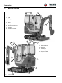
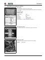
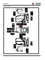
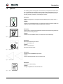
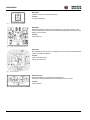
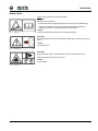
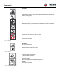
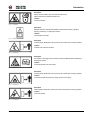
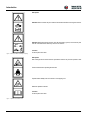
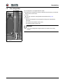
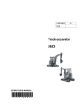
1000183743
2.2
0309
Track Excavator
1404
OPERATOR’S MANUAL
1
0
0
0
1
8
3
7
4
3
www.wackerneuson.com
Introduction
Introduction
1
1.1
Introduction
Important operator information
Store the Operator’s Manual in the storage compartment under the seat.
This Operator’s Manual contains important information on how to work safely, correctly
and economically with the machine. It provides information and instructions for all
operators, regardless of their experience level. It helps to avoid dangerous situations and
reduce repair costs and downtimes. Furthermore, the reliability and the service life of the
machine will be increased by following the instructions in the Operator’s Manual. This is
why the Operator’s Manual must always be kept at hand in the machine.
Your own safety, as well as the safety of others, depends to a great extent on how the
machine is moved and operated. Thoroughly read and understand the information in this
Operator's Manual before operating the machine for the first time. This Operator’s Manual
will help to familiarize yourself more easily with the machine, thereby enabling you to use it
more safely and efficiently.
Before operating the machine for the first time, carefully read the section "Safety
Instructions" to learn how to operate the machine safely. As a rule, keep the following in
mind: Careful and prudent working is the best way to avoid accidents!
Special instructions
• Instructions are provided for bucket attachments. No instructions are provided for other
attachments. Refer to the specific attachment operator's manual for safe operation.
• Wacker Neuson reserves the right to make product improvement changes during the
course of series production of this machine.
• Modifying the manufacturer specification and configuration of this machine, or using
unapproved attachments, can cause personal hazards and damage the machine.
Contact your Wacker Neuson dealer for additional information and clarification
regarding modifications.
Operational safety and readiness of the machine do not only depend on your skill, but also
on maintenance and service of the machine. This is why regular maintenance and service
work is absolutely necessary. Extensive maintenance and repair work must always be
performed by an expert with appropriate training. Insist on using Wacker Neuson original
spare parts when performing maintenance and repair work. This ensures operational
safety and readiness of your machine, and maintains its value.
• Special equipment and superstructures are not described in this Operator’s Manual.
• We reserve the right to improve the technical standard of our machines
• Modifying Wacker Neuson products and fitting them with additional equipment and
tools not included in our delivery program requires written authorization from Wacker
Neuson, otherwise warranty and product liability for possible damage caused by these
modifications shall not be applicable.
Your Wacker Neuson dealer will be pleased to answer any further questions regarding the
machine or the Operator’s Manual.
Abbreviations / symbols
• This symbol stands for a list.
• Subdivision within lists or an activity. Follow the steps in the recommended
sequence.
☞ This symbol requires you to perform the activity described.
➥ Description of the effects or results of an activity.
n. s. = not shown.
“Opt.” = option; Stated whenever controls or other components of the machine are
installed as an option.
This symbol shows the traveling direction – for better orientation in figures and
graphics.
OM 1404 US – Edition 2.2 * 1404b110.fm
1-1
Introduction
1.2
Machine overview
1
9
1 Lights
2
Boom light
3
Boom
4
Handle
5
Auxiliary hydraulics
6
Lifting and tie-down point
7
Door latch
8
Door handle and lock
3
1
5
10
12
6
9
2
5
9
Rotating beacon
10
Rear light
11
Muffler pipe
12
Lubrication point for track tension
13
Engine air intake
8
7
4
11
12
6
Fig. 1:
1-2
13
Machine outside views
OM 1404 US – Edition 2.2 * * 1404b110.fm
Introduction
1.3
Brief description
The model 1404 excavator is a self-propelled work machine.
Get informed on and follow the legal regulations of your country regarding the use of
excavators.
This machine is a versatile and powerful tool for moving earth, gravel and debris on
construction sites and elsewhere. A wide range of attachments accounts for the numerous
applications of the machine, among others hammer and grab applications. See Chapter
“Fields of application, attachments” on page 1-4.
The main components of the machine are:
• FOPS (Falling Object Protective Structure), TOPS (Tip Over Protective Structure) and
ROPS (Roll Over Protective Structure) tested open cab (standard)
• FOPS (Falling Object Protective Structure), TOPS (Tip Over Protective Structure) and
ROPS (Roll Over Protective Structure) tested closed cab (option)
• Model 1404: water-cooled Yanmar three cylinder diesel engine
• Sturdy steel sheet chassis; rubber-mounted engine
Traveling drive
The diesel engine permanently drives the gear pump whose oil flow is sent to a hydraulic
motor for each track drive.
Work hydraulics
The diesel engine drives the joint gear pump for the work hydraulics. The oil flow of this
pump depends on the diesel engine speed only.
Cooling system
The indicator lights in the instrument panel of the machine ensure constant monitoring of
the engine and hydraulic oil temperature, as well as of the coolant temperature and level.
Cab
Do not modify or attempt to repair the ROPS cab or ROPS structure. A bent or damaged
ROPS will no longer protect the operator in the event of a tipping incident and must be
replaced. Contact your Wacker Neuson dealer for instructions or clarification.
The ROPS is a special safety device designed and produced to exacting material and
assembly standards for certification. Bending, heating, welding, cutting, or drilling holes in
the ROPS will reduce the protection performance in a tipping incident.
Fasten your seatbelt, otherwise you may be thrown around or even outside the cab and
crushed. Therefore always fasten your seatbelt as you drive and work with the machine.
Tighten the seatbelt before starting work with the machine.
OM 1404 US – Edition 2.2 * 1404b110.fm
1-3
Introduction
1.4
Fields of application, attachments
The attachments installed determine the intended use of this machine.
NOTICE
In order to avoid damage to the machine, only the attachments listed
below have been certified for installation on the machine.
☞ Contact your Wacker Neuson dealer if you wish to use other attachments.
Using tools of other manufacturers, or tools which have been released for other excavator
types, may reduce the machine's output and stability considerably, and can also cause
damage to the machine and injuries to the operator or the staff.
Always compare the weight of the tool and its maximum payload with the indications in the
lift capacity table. Never exceed the maximum payload stated in the lift capacity table.
Use: attachment
The measurements are Metric (Imperial).
Possible attachments
Description of attachment
Capacity
Item no.:
Complete quickhitch facility
-
1000004049 1404
Required for operation of
Wacker Neuson quickhitch system
23 l (0.8 ft3)
1000093251 1404
-
23 l (0.8 ft3)
1000017084 1404
For quickhitch facility
27 l (1.0 ft3)
1000093249 1404
-
27 l (1.0 ft3)
1000017085 1404
For quickhitch facility
35 l (1.2 ft3)
1000093252 1404
-
35 l (1.2 ft3)
1000017087 1404
For quickhitch facility
44 l (1.6 ft3)
1000093253 1404
-
44 l (1.6 ft3)
1000017088 1404
For quickhitch facility
53 l (1.9 ft3)
1000093254 1404
-
53 l (1.9 ft3)
1000017089 1404
For quickhitch facility
50 l (1.8 ft3)
1000093255 1404
-
50 l (1.8 ft3)
1000017090 1404
For quickhitch facility
56 l (2.0 ft3)
1000096515 1404
-
56 l (2.0 ft3)
1000017091 1404
For quickhitch facility
69 l (2.4 ft3)
1000093460 1404
-
68 l (2.4 ft3)
1000093335 1404
For quickhitch facility
Bucket B = 250 mm (9.8 in.)
Bucket B = 300 mm (11.8 in.)
Bucket B = 400 mm (4.4 in.)
Bucket B = 500 mm (1.8 in.)
Bucket B = 600 mm (1.12 in.)
Offset bucket B = 850 mm (33.5 in.)
Offset bucket B = 1000 mm (39.4 in.)
Ditch cleaning bucket B = 850 mm (33.5 in.)
1-4
Excavator
Remarks
OM 1404 US – Edition 2.2 * * 1404b110.fm
Introduction
Description of attachment
Capacity
Item no.:
82 l (2.9 ft3)
1000096528 1404
-
80 l (2.8 ft3)
1000096518 1404
For quickhitch facility
Hammer mount console
-
1000020344 1404
Universal mount
Hammer mounting kit
-
1000157326 1404
Mount for Wacker Neuson
hammers
Ditch cleaning bucket B = 1000 mm (39.4 in.)
1.5
Excavator
Remarks
Operator qualifications
Requirements to be met by the operator
Earth moving machinery may be moved and serviced only by persons who meet the
following requirements:
• 18 years or older.
• Physically and mentally suited for this work.
• Persons have been instructed in driving and servicing the earth moving machinery and
have proven their qualifications to the contractor.
• Persons are expected to perform work reliably.
• They have been appointed by the contractor for driving and servicing the earth moving
machinery.
• They are informed on and follow the legal regulations of your country.
OM 1404 US – Edition 2.2 * 1404b110.fm
1-5
Introduction
1.6
EC Declaration of Conformity version 1404
EC Declaration of Conformity
according to EC Directive 98/37/EC, 2000/14/EC Appendix 6
Wacker Neuson Linz GmbH
Haidfeldstrasse 37
A-4060 Linz-Leonding
declare, under their own responsibility, that the product
Product name
Model
Version
Serial no.
Wacker Neuson track excavator 1404
1404
1404
-----------
to which this declaration refers, corresponds to the pertinent fundamental
requirements regarding safety and health of
EC Directive 98/37/EC
and the requirements of further pertinent EC Directives and standards.
ISO 3471 and
EN 13510
2000/14/EC
Tested
Administrative unit reported
according to Appendix 6
information
Noise level
dBA
Measured value
93
Guaranteed value
92.7
TÜV München
(Munich/Germany
Industrial Supervisory
Board) Westendstrasse
199
D-80686 Munich
The following standards and/or technical specifications have been used for the
proper application of the requirements regarding safety and health stated in
the EC Directives:
EN 474-1, EN 474-3, EN292-1, EN 292-2, ISO 3471, EN 13510;
Place of storage of technical documentation:
Wacker Neuson Linz GmbH
Department: R & D
Haidfeldstr. 37
A-4060 Linz-Leonding
Linz-Leonding, (date) _ _ . _ _ . _ _ _ _
Josef Erlinger
Wacker Neuson Linz GmbH
1-6
OM 1404 US – Edition 2.2 * * 1404b110.fm
Introduction
1.7
Type labels and component numbers
Serial number
The serial number is stamped on the machine chassis.
It is also located on the Product Identification Number plate riveted to the front left chassis
of the machine.
Type label information
Example: 1404
Fig. 1:
Type label: location
Machine model:
1404
Serial no.:
e.g. AF01272
Model year:
2006
Power, SAE:
13.2 kW (17.7 hp)
Dead weight:
1550 kg (3417 lbs)
Other information – see chapter 6 Specifications on page 6-1
Fig. 2:
Type label
Cab certification number
The certification label (arrow) is located at the top right on the cab frame.
Fig. 3:
Cab type label
Engine serial number
The type label (arrow) is located on the cylinder-head cover (engine).
Example:
Fig. 4:
Yanmar 46557
Diesel engine number
OM 1404 US – Edition 2.2 * 1404b110.fm
1-7
Introduction
Label overview
1-8
OM 1404 US – Edition 2.2 * * 1404b110.fm
Introduction
1.8
Symbols
The following symbols are displayed on the machine to provide pictorial information to the
user. The information and explanations are provided to avoid misinterpretation by the user.
The symbols have been chosen to provide important information to those involved with
operating, adjusting, maintaining, and repairing this machine.
Description
Locates the lifting points for hoisting the excavator with lifting devices (slings, chains, or
cables).
Location
On either side of the stabilizer blade, and on either side of the boom near the cylinder end
of the stick hydraulic cylinder mounting and either side of cabin roof.
Fig. 5:
Eye hook label
Description
Tie down points. Location points designated for tie down of the machine during transport to
prevent movement during transport.
Location
On either side of the stabilizer blade, and on either side of the undercarriage.
Fig. 6:
Label for points used for strapping down the
machine
Description
Noise levels produced by the machine.
LWA = sound power level
Location
Cabin: On the left window.
Canopy: On the seat console.
Fig. 7:
Noise level label
Description
This label shows the forward driving direction.
Location
On each undercarriage at the idler end of the structure.
Fig. 8:
Direction arrows
Description
Fill location for diesel fuel only.
Location
In engine compartment near fuel tank filter neck.
Fig. 9:
Diesel
OM 1404 US – Edition 2.2 * 1404b110.fm
1-9
Introduction
Description
Hydraulic oil reservoir. Use hydraulic fluid only.
Location
In engine compartment.
Fig. 10: Hydraulic oil
Description
Explains the functions of the joysticks (control pattern "A") and of other controls. If the
machine is fitted with the "selection valve" check before starting the machine which control
pattern you have chosen!
Location
On the cabin roof.
Fig. 11: Functios of the joysticks (control pattern ’’A“)
Description
Shows the main service intervals. For complete list of service interval see the maintenance
section of this Operator's Manual.
Location
Cabin: On the rear window.
Canopy: On roof window.
Fig. 12: Main service intervals
Description (Opt.)
Explains the functions of the joysticks (control pattern "B").
Check before starting the machine which control pattern you have chosen!
Location
On the cabin roof.
Fig. 13: Opt. Functions of the joysticks(control pattern ’’B’’)
1-10
OM 1404 US – Edition 2.2 * * 1404b110.fm
Introduction
Safety Labels
Always follow the instructions on the safety labels!
Description
The label means the following:
• Potential high pressure grease discharge from the track tension adjustment fitting.
• Always the maintenance section of this Operator's Manual before releasing or
tightening the tracks to avoid potential injury from ejected grease.
Fig. 14: Tighten tracks
Location
On the undercarriage near the opening to insert the grease fitting.
Description
Stop the engine before opening or dismantling the safety devices ( like engine hood, fan
guard,....)
Location
On the engine cover.
Fig. 15: Prohibitory label
Description
Pinch point hazard. Always use the handles to open and close the front window.
Always fasten the front window with both locks.
Location
On front window.
Fig. 16: Front window
OM 1404 US – Edition 2.2 * 1404b110.fm
1-11
Introduction
Description
This safety label warns of the following hazards:
Cutting hazard. Cooling fan can cut when rotating. Stop engine before working on the
engine or cooling system.
Entanglement hazard. You can be pinched or entlanged in the engine V-belt when the
engine is running. Stop engine before working on the engine.
Hot surface and burn hazards. Do not touch.
Contents are under pressure. Do not remove cap.
Location
In the engine compartment
Fig. 17: Rotating V-belt
Description
Hot surface! Do not touch.
Location
Engine compartment near muffler system.
Fig. 18: Hot surfaces
Description
The tank is hot and under pressure!
• Allow the fluids to cool down!
Carefully and slowly open the cover only after the fluids has cooled down, to allow the
pressure to escape.
Wear safety goggles and gloves when opening the cover.
Location
In the engine compartment.
Fig. 19: Hydraulic oil tank under pressure
1-12
OM 1404 US – Edition 2.2 * * 1404b110.fm
Introduction
Description
Always use the handles to open and close the front window.
Always fasten the front window with both locks.
Location
On the front window.
Fig. 20: Front window
Description
Attention! Read and understand the Operator's Manual before starting, operating,
adjusting, maintaining, or repairing the machine.
Location
On the b-pillar in the cabin.
Fig. 21: Read the Operator’s Manual
Description
Crushing hazard. Bystanders must stay clear of the machine when it is being operated.
Location
On either side of the boom structure.
Fig. 22: Keep distance 1
Description
Accumulator is under high pressure. Always read Service Manual before maintaining or
repairing the machine.
Location
On the bracket near to the accumulator.
Fig. 23: Under pressure
Description
Crushing hazard. Bystanders must stay clear of the machine when it is being operated.
Location
On the left and right side of the boom swing console on the chassis.
Fig. 24: Keep distance 2
Description
Collision hazard. Bystanders must stay clear of the machine when it is being operated.
Location
On the rear window.
Fig. 25: Keep distance 3
OM 1404 US – Edition 2.2 * 1404b110.fm
1-13
Introduction
Description
Attention: Remove starter key and read the Service Manual before servicing the machine.
Attention: Before leaving the machine, lower all equipment to ground, remove the key and
lock the controls Remove starter key and lock out machine.
Location
Fig. 26: Read manual before maintaining or repairing
On the b-pillar in the cabin.
Description
Risk of being thrown from the machine. Operate the machine only from the operator's seat.
Fasten seat belt when operating the machine.
Operate within stability limits of machine to avoid tipping over.
Read the Operator's Manual.
Location
On the b-pillar in the cabin.
Fig. 27: Operator’s seat and fasten seat
1-14
OM 1404 US – Edition 2.2 * * 1404b110.fm
Introduction
1.9
Fire extinguisher
The fire extinguisher is not supplied with the machine.
☞ Retrofitting a fire extinguisher according to NFPA must be performed by an authorized
Wacker Neuson service center.
☞ Location:
➥ In the cab, on the left in driving direction behind the seat (see Fig. 28).
☞ Installation:
• Mount the fire extinguisher on the cab profile according to the manufacturer’s
instructions.
• The maximum hole diamenter is 6mm (0.24’’)
• The maximum number of holes is two.
Important!
Check the fire extinguisher at regular intervals, also make sure it is safely
mounted.
175 mm (7’’)
Fig. 28: Position of fire extinguisher
OM 1404 US – Edition 2.2 * 1404b110.fm
1-15
Introduction
1-16
OM 1404 US – Edition 2.2 * * 1404b110.fm