1
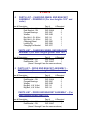
Rubber Door System
INSTALLATION INSTRUCTIONS
WD 1000 RUBBER DOOR
________ WIDE x ________ HIGH
WARREN DOOR SALES
“THE INDUSTRIAL SALES PEOPLE”
P.O. BOX 70
332 PLANT STREET
NILES, OHIO 44446
TELEPHONE: 1-800-ALL DOOR
(1-800-255-3667)
FAX: 330-652-5939
Table of Contents
Forward
3
1. Limited Warranty
4
2. Features
2.1
Standard Features
2.2
Optional Features
5
5
3. WD 1000 General Door Arrangement Drawing
6
4. Components
4.1
Guides
4.2
Drive End Bracket
4.3
Spring End Bracket
4.4
Counterbalance Spring Barrel
4.5
Curtain
4.6
Idler Barrel
4.7
Charging Wheel
4.8
Bottom Bar
4.9
Electric Operator
7
7
7
7
7
8
8
8
8
5. Erection Instructions
5.1
Set up prior to erection (Drawing A)
5.2
Guides (Drawing B.)
5.3
End Brackets (Drawing C)
5.4
Spring Barrel and Curtain
5.5
Electric Operator (Drawing E)
5.6
Charging Wheel and Pre-Charge (Drawing F)
5.7
Idler Barrel
5.8
Operator Electrical Connection
5.9
Hood Cover
9-10
11-12
13-15
16
16-17
18-19
20
21
21
6. Maintenance Guide
22
7. Curtain Removal and Re-installation
7.1
Remove from guide system
7.2
Reinstallation of curtain after an impact has
Removed the curtain from the guide system.
23
23
8. Parts List
8.1
Guide Assembly (Drawing J.)
8.2
Charging Wheel & End Bracket Assembly
(Drawing K)
8.3
Drive End Bracket Assembly (Drawing L)
24
25
24 & 26
24 & 27
FORWARD
THE INFORMATION CONTAINED IN THIS DOCUMENT IS
SUBJECT TO CHANGE WITHOUT NOTICE!!!
Warren Door provides this information as a service to its customers. We
strongly recommend that you review and study the information provided. Your
complete understanding of the door system and its requirements is a priority and
will allow you to enjoy the unique design features of the WD 1000. If you have
any questions regarding the following instructions, contact the factory before
proceeding. Any deviation from the following instructions will result in improper
operation of the door system, damage to the rubber curtain or its components,
and will void the warranty extended by Warren Door of its parts manufactures.
REMEMBER IT IS EASIER TO HANDLE QUESTIONS THAN IT IS
TO HANDLE UNNECESSARY MISTAKES.
WARREN DOOR SALES LIMITED WARRANTY
ALL RUBBER DOOR SYSTEMS MANUFACTURED BY WARREN DOOR ARE
WARRANTED AGAINST DEFECTS IN MATERIALS AND WORKMANSHIP AS
FOLLOWS: DOOR SYSTEMS IN GENERAL-ONE (1) YEAR FROM THE DATE OF
PURCHASE; RUBBER CURTAIN – FIVE (5) YEARS FROM THE DATE OF
PURCHASE.
THIS WARRANTY COVERS DEFECTIVE MATERIAL AND WORKMANSHIP. THE
WARRANTY APPLIES ONLY IF THE RECOMMENDED INSTALLATION AND
MAINTENANCE PROCEDURES OUTLINED IN OUR SERVICE MANUAL AND
INSTALLATION BOOK ARE STRICTLY FOLLOWED. CONTACT WARREN DOOR
FOR A LIST OF TRAINED INSTALLERS IN YOUR AREA.
DEFECTIVE PARTS MUST BE RETURNED TO OUR SHOP, FREIGHT PREPAID,
ACCOMPANIED BY A COPY OF OUR INVOICE FOR OUR INSPECTION AND
DETERMINATION. WE DO NOT AUTHORIZE AND WILL NOT PAY FOR ANY
OUTSIDE REPAIR. OUR OBLIGATION UNDER THIS WARRANTY SHALL BE
LIMITED TO, AS WE MAY ELECT, EITHER REPLACEMENT OF ANY DEFECTIVE
PARTS FREE OF CHARGE OR PAYMENT EQUAL TO THE COST OF REPAIR
BASED ON OUR ESTIMATE AND JUDGMENT. WE SHALL NOT BE LIABLE FOR ANY
LABOR CHARGES, TOWING CHARGES, LOSS OF TIME CHARGES, NOR ANY
OTHER CHARGES. THIS IS OUR ONLY WARRANTY.
IN CASES WHERE THE MANUFACTURER’S WARRANTY OF CERTAIN
COMPONENT PARTS CONNECTED WITH OUR DOOR SYSTEMS (I.E., ELECTRICAL
MOTORS, SWITCHES, ETC.) IS LESS THAN THE WARREN DOOR WARRANTY,
THE MANUFACTURER’S WARRANTY WILL APPLY.
THE WARREN DOOR WARRANTY DOES NOT INCLUDE REPLACEMENT OF
PARTS DUE TO NORMAL WEAR AND TEAR, DAMAGE BEYOND THE CONTROL OF
WARREN DOOR (I.E.., DAMAGE IN TRANSIT, IMPACTS, ETC.)
OR ANY LABOR CHARGES INCURRED ON THE REMOVAL AND/OR
REPLACEMENT OF DEFECTIVE PARTS.
ALL WARRANTY CLAIMS MUST BE MADE TO WARREN DOOR. ALL RETURNS
MUST BE SHIPPED “PREPAID FREIGHT” TO:
WARREN DOOR
332 PLANT STREET
NILES, OHIO 44446
DO NOT EVER USE PETROLEUM BASED PRODUCTS
ON THE CURTAIN. IF DONE, THIS VOIDS ALL
WARRANTY ON THE CURTAIN.
FEATURES
2.1 STANDARD FEATURES
1.
2.
3.
4.
5.
6.
7.
8.
9.
10.
11.
12.
13.
American Made door components and power operator.
Rubber Curtain.
WD Safety bottom bar.
Electric reversing safety edge.
Guides.
Hood.
Idler barrel.
Counterbalance spring barrel.
End Brackets.
Complete standard mounting hardware package.
NEMA I interior open-close-stop push button station.
NEMA I 1hp (or 2hp) power operator depending on curtain size.
1 Set of Photo-eyes.
2.2 OPTIONAL EQUIPMENT (Listed, but not limited to)
1.
2.
3.
4.
5.
6.
7.
8.
9.
10.
11.
12.
Chain Hoist Operation.
Pneumatic Safety Edge.
Windows.
Various NEMA Requirements.
Radio Controls.
Time Delay Controls
Key Switch.
Ceiling Pull Switch.
Card Reader.
Vehicle Detector.
Stainless Steel.
Galvanized Steel.
4. COMPONENTS
4.1 GUIDES
The guides are pre-engineered to corresponding door heights that, when placed
vertically on each side of the opening, direct the rubber curtain’s travel and
manage how the wind-lock of the curtain reacts during impact and wind pressure.
The top portions of the guides are hinged to allow the curtain to be re-inserted
should it be pulled out of the guides.
4.2 DRIVE END BRACKET
The drive end bracket is mounted to the top of the guide system that holds it to
the face of the door opening. This bracket supports the operating device,
counterbalance spring barrel, idler barrel and bearings.
4.3 SPRING END BRACKET
The spring end bracket is mounted to the top of the opposite guide as the drive
end bracket. The guide system holds the spring end bracket to the face of the
door opening. This bracket has a slotted channel attached to it in which the
charging wheel keeper pin is placed to retain tension on the counterbalance
spring barrel. This bracket also supports the counterbalance spring barrel, idler
barrel and bearings.
4.4 COUNTERBALANCE SPRING BARREL
This counterbalance spring barrel is constructed of a steel barrel that contains
helically wound torsion springs. This barrel is enclosed with end plugs on the
drive end and spring end that holds the pipe concentric to the shaft. The
counterbalance spring has sufficiently sized springs to help lift the weight of the
curtain during operation. The counterbalance spring barrel allows an anchoring
point to which the top of the curtain is secured to.
4.5 CURTAIN
The curtain is a ¼” nominal S.B.R. (Styrene Butadiene Rubber) R.M.A. Grade II
material with R.M.A. Grade II Covers. A ½” R.M.A. Grade II material is attached
to the curtain to form beveled wind-locks. This wind-lock is designed to react in
specific ways during impact and to help maximize the thermal properties of the
door system.
4.6 IDLER BARREL
The idler barrel is constructed of a steel tube with end plugs on either end that
support the shaft. This shaft attaches the idler barrel to the end bracket and
mounts into the pillow block bearings. The idler barrel maintains the curtain
position in relationship to the lintel of the opening. This “curtain to lintel”
relationship helps the door system’s thermal control properties.
4.7 CHARGING WHEEL
The charging wheel mounts to the spring end of the counterbalance spring barrel
shaft and is held in place with a keeper pin. The charging wheel allows tension
to be placed on the torsion springs and is held by a charging wheel keeper pin
placed through a slotted channel block on the spring end bracket.
4.8 BOTTOM BAR
The bottom bar is an angle and flat steel component that leads the curtain in the
guide system. It contains a safety notch with a span plate that allows the bottom
bar to react during impacts, and insures proper performance of the wind-lock
during impacts. The bottom bar also holds either a standard electric safety edge
or an optional pneumatic safety edge.
4.9 ELECTRIC OPERATOR
The electric operator is a NEMA I unit that consists of a NEMA 1 factory prewired control panel, a fully adjustable traveling cam type limit switch, a
continuous duty tri-voltage motor, shock absorbing couplings, an emergency
operation hand chain, a heavy duty worm and gear reducer running in an oil
bath, an interior 3 button push button station and a solenoid operated brake
design.
5. ERECTION INSTRUCTIONS
SEE DOOR GENERAL ARRANGEMENT DRAWING WD1000
5.1 SET UP PRIOR TO INSTALLATION
* NOTE: It is absolutely vital to the proper operation of the door that the
guides be erected according to the strict instructions provided. Any
deviation from these instructions will cause the WD 1000 to operate
improperly and cause damage to its components. If you have any
questions or need clarification please contact the factory at: 1-800-ALLDOOR (1-800-255-3667).
a. Determine that the opening jambs are true by measuring the
width at the lintel line and the floor level. These dimensions
should be equal (only ¼” maximum tolerance).
b. Check the measurements of the opening to the width and height
of the door ordered. (See Drawing A.) The guides must be
spaced horizontally by the given “C” dimension (shown on the
General Arrangement Drawing WD1000) and must be set
plumb.
c. Ensure that the jambs are perpendicular by using a proper level.
d. At the ends of the lintel measure from the underside of the lintel
to the floor of the opening. There should be no more than ½”
difference between the opening measurement and the height of
the door ordered.
e. Finally, using a level or transit, make a horizontal line across the
opening to ensure the guides are level when installed.
* NOTES:
If any of the measurements exceed the maximum tolerances
specified CONTACT THE FACTORY BEFORE PROCEEDING WITH THE
INSTALLATION!
DO NOT remove the straps from the curtain until instructed to do so. By leaving
the straps on, your job will be made easier during the installation.
5.2 STEP I: ERECTION OF GUIDES
a. The guides for the door systems are marked “left guide” and “right
guide”. These guides are pre-assembled and do not require
disassembly prior to installation.
b. Refer to Drawing B. Place the Left Guide (with hinged portion facing
out) flush with the inside edge of the steel column or frame on the left
side of the opening. Position the top of the retainer to correspond with
the mark line 6” above the underside of the lintel. Ensuring that the
guide is exactly perpendicular, attach it to the steel column of the
frame by tack welding (using approximately 12” centers) to guide leg
and lag bolt to the wall.
c. Repeat step b with the Right Side.
d. The clearance of ½” or 9/16” in the guide opening (see arrangement
drawing WD1000) has been determined at the factory. It allows the
curtain to move freely within the guides. However, during shipment or
assembly, the guide opening may have been altered so we
recommend that you pass a ½” or 9/16” bolt through the guide opening
to verify that the opening is not too wide or too narrow for the curtain to
pass. Any deviation from this measurement could result in damage to
the curtain or reduction in the wind load capacity of the door. If
variations do exist in the opening of the guide, such as being too
narrow, simply spread the opening with a pry bar. If the opening is too
wide, strike the outside section of the guide using a block or hammer.
e. Unbolt the hinged portion at the top of the guides so that the swinging
part of the guide is completely opened. This will make it easier to
insert the curtain later in the installation process.
Congratulations! The installation of the guides is complete. It would be to your
benefit to briefly review your work at this point to ensure proper installation of the
guide system.
5.3 STEP II: PLACEMENT OF END BRACKETS
a.
The end brackets are the flat steel plates that are shaped in
somewhat of an octagon shape. Your components should include
two of these brackets. Carefully slide the two end brackets onto the
shafts of the counterbalance spring barrel. Reference Drawing C.
The end bracket that has the slotted “c” channel piece welded
perpendicular to the plate is the end bracket that goes on the
winding wheel side. The other end bracket will then slide over the
shaft at the other end of the counterbalance spring barrel; this is the
driven side of the door. *NOTE: The set screws are NOT to be
tightened down at this point in time.
b.
NOTE: It will work to your advantage during installation if you
position the bottom bar between the counterbalance spring barrel
and the wall while lowering the assembly into the guides. At this
point remove the nuts and washers from the guide angle bracket
studs if attached.
c.
Using a device sufficient to raise the weight of the door, position the
spring barrel (with the curtain end bracket assemblies) until it is
above the guide angles. Lower the assembly until the brackets rest
on the angle shelf above the guides. Bolt the brackets to the top of
the guides. Bolt the brackets to the guide angles (heads of the
bolts should be on the inside to permit the curtain clearance).
Replace the washers and nuts on the bracket studs.
5.4
STEP III: PLACEMENT OF SPRING BARREL & CURTAIN.
a. With the curtain and end brackets in place, use a plumb line
across the two end brackets to insure that the door is level. End
brackets can be repositioned by loosening bolts and adjusting
up or down within the slotted holes. The end bracket support on
the top of the guide angle may require shimming.
b. Center the curtain between the end brackets and tighten the
bearing screws.
5.5
STEP IV: PLACEMENT OF ELECTRIC OPERATOR
a.
Hand Tighten the operator mounting bracket to the drive end
bracket.
b.
Bolt the operator unit to the operator mounting bracket with
the four (4) bolts provided.
c.
Remove the cover from the operator limit box, (See Drawing
E). If the “open” limit switch is not already actuated, engage
the chain hoist on the operator and manually turn until the
open limit is actuated. Leave the cover off in case further
adjustments need to be made.
d.
Place the larger driven sprocket on the operator end of the
counterbalance spring barrel shaft.
e.
Place the smaller drive sprocket on the operator drive shaft if
not already placed.
f.
Attach the chain around the two sprockets, insure proper
alignment of chain, and tighten each set screw. Adjust the
slack in the chain (insure that the amount of slack does not
exceed ¼” by moving the operator unit. Tighten the two (2)
mounting bolts left hand tightened in step 5.5-a.
OPERATOR MOUNTING IS NOW COMPLETE. AS IN PREVIOUS
STEPS, CHECK YOUR WORK FOR ACCURACY!
5.6
STEP V: CHARGING WHEEL PLACEMENT AND
PRECHARGING OF COUNTER BALANCE SPRING
BARREL.
a.
Place the charging wheel on the spring end bracket side of
the counterbalance spring barrel shaft. Rotate the wheel by
hand to determine the spot where there is no tension on the
springs, this is your neutral point.
b.
Insert the charging wheel keeper in the slotted angle with the
button head up on the top of the channel. Then slip the pin
into the nearest hole of the charging wheel and mark that
charging slot to indicate the initial starting point of charging
wheel.
*THE REQUIRED NUMBER OF CHARGING WHEEL
TURNS ARE ________ FOR THIS DOOR. (See Drawing
“F”)
c.
Insert the winding bar into a hole in the charging wheel.
Apply pressure to the tension rod in the direction of the
arrow on drawing “F”. While continuing to apply pressure on
the rod, remove the charging wheel keeper pin, rotate the
charging wheel in the direction of the arrow – one hole – and
reinsert the charging wheel keeper pin.
You are now ready to fully charge the counterbalance spring
barrel. Keep tension on the charging wheel again and
remove the charging wheel keeper pin. By using the mark
that was made on the charging wheel, turn the charging
wheel the necessary number of turns and replace the
charging wheel keeper pin.
BE CAREFUL NOT TO TRY AND TURN THE CHARGING
WHEEL TOO MUCH AT ONE TIME. IF YOUR GRIP ON THE
TENSION RODS WOULD SLIP, SERIOUS INJURY COULD
RESULT.
The pre-charging of the counterbalance spring barrel is complete. Once again
review your work for accuracy. Any deviation from the specified charging
instructions will cause the door to work improperly and may cause damage to the
door system components.
5.7 STEP VI: PLACEMENT OF IDLER BARREL
a.
Remove the shipping straps from the door curtain.
b.
Use the manual chain hoist to lower the curtain into the guide
system, two (2) feet below the lintel.
c.
Place two (2) bearings, one on each side, of the idler barrel shaft.
Raise the idler barrel with bearings under the curtain and into the
slotted portion of the end brackets. Bolt the bearings to the end of
the brackets with the heads of the bolts on the inside of the
brackets. Now bolt the rest of the pillow block holes using the
special rectangular washers furnished through the guide angle
bolting.
d.
Position the roll equal distance between each end bracket and
tighten bearing set screws.
e.
Lower the curtain into the guide system 18” below the hinged guide
sections. Close the hinged guide retainers and bolt sections to the
guide angle.
The distance between the curtain and the wall is 1”. (If the
clearance tolerances are not within the specifications the clearance
can be adjusted by loosening the bolts on the idler barrel bearings
and moving the idler barrel the proper direction. After adjustment is
made, tighten the bearing bolts again and recheck clearance
measurement).
f.
It is necessary at this point to check the tracking of the curtain
inside the guide system. Unbolt one of the hinged guide sections.
While keeping your attention on the outer edge of the curtain, lower
the curtain with the chain hoist and observe the travel of the curtain.
If the curtain tracks to either side of the guide, it is necessary to
realign the counterbalance spring barrel. To do this, simply raise or
lower the counterbalance spring barrel. After operating the door
again by chain hoist and it is determined that the curtain is tracking
properly, bolt the hinged portion of the guide system again to the
mounting angle.
THE PLACEMENT OF THE IDLER BARREL IS NOW COMPLETE.
AGAIN REVIEW YOUR WORK TO INSURE THAT YOU HAVE
COMPLETED THE STEPS PROPERLY.
5.8 STEP VII: OPERATOR ELECTRICAL CONNECTION
a.
Connecting to the power supply.
Consult local electrical codes before proceeding with permanent
installation.
WARNING: Exercise caution when engaging electrical operator.
The drive and limiting chains are exposed and if turning, could
cause injury. Wiring diagrams can be found inside the control box
cover and install the control stations as required.
On Three phase units, make certain that the operator rotates in the
correct direction. If the direction is wrong, the limit switches will not
function and damage will occur to the door. It is strongly
recommended that the door be moved manually to mid-position
before turning the power on so that it may be stopped before any
damage can occur should the rotation be incorrect. If the direction
is incorrect, reverse any two (2) of the three (3) incoming power
supply leads to correct rotation.
b.
Limit switch adjustment
Depress traveling cam retaining bracket to turn traveling limit nuts.
Turning the traveling limiting nut away from the open limit switch
and toward the center of the cam shaft increases upward door
travel. Turning traveling limit toward the open limit and away from
the center of the cam shaft decreases upward travel of the door.
Make sure that the retaining bracket engages in slot after each
adjustment. Use the STOP button to stop the door until limits are
set in the correct position.
5.9 STEP VIII: HOOD COVER PLACEMENT
a.
b.
For a one piece cover, set the hood on top of the bracket with the
top flange of the hood tight against the wall. Drill six (6) spaced
holes in the supporting angle on the end brackets and anchor with
the self tapping screws provided.
For a two or more piece hood cover, fasten cover support(s) to the
wall on equal centers, and attach the hood cover to the end
brackets and the supports as described in 5.9-a.
THE DOOR INSTALLATION IS NOW COMPLETE.
6. Maintenance
While the WD1000 has been designed to help eliminate
maintenance requirements traditionally required by
conventional door systems, by implementing the following
minor maintenance checks you will get the maximum life from
your new rubber door.
a.
Door Assembly
All external bearings should be greased via the
attached fitting at least once a year. Standard wheel
bearing grease is recommended.
b.
Electric Operator
To help extend life, the drive chain should be
lubricated once a month. Also the slack should be
checked and should not exceed ¼”. If the slack
exceeds ¼” tighten the chain by adjusting the position
of the power operator. (See 5.5 Step IV: Placement
of Power Operator for instructions). Check the
level of oil in the power operator reducer once a year
to insure that no leaks have developed in the oil
seals. Check the wiring connections and power
supply wiring for continuity once a year.
c.
Guides
Check to insure that the clearance in the guide
opening is maintained at the specified width, ½” or
9/16”. This should be checked every three months by
passing a ½” or 9/16” bolt through the guide opening.
If the clearance is too narrow, spread the opening to
the correct width. If the clearance is too wide, strike
the outside of the windlock guide using a block or
hammer.
d.
Curtain
In the unlikely event that a curtain should tear, it
possibly, may be addressed in the field, depending on
the severity. Consult our engineering office for the
details on the rubber curtain repair kit at 1-800-2553667. DO NOT EVER USE PETROLEUM BASED
PRODUCTS ON THE CURTAIN. IF DONE, THIS
VOIDS ALL WARRANTY ON THE CURTAIN.
7. CURTAIN REMOVAL AND REINSTALLATION
7.1 REMOVAL FROM THE GUIDE SYSTEM
If it becomes necessary to remove the curtain from the guide system, use the
following process:
7.2
a.
Unbolt the top hinged section of the guide system.
b.
Raise the curtain until the bottom bar is at the bottom portion of the
hinged section.
c.
Lift the curtain and remove it from the guide system.
d.
Lower the curtain and make sure that it does not hang up on any
part of the guide system. (Reverse this order to re-install.)
REINSTALLATION AFTER AN IMPACT HAS REMOVED THE
CURTAIN FROM THE GUIDE SYSTEM
a.
Straighten the bottom bar assembly and replace the span plate as
well on all sheared span plate bolts.
b.
Raise the curtain to the hinged portion of the guide system.
c.
Unbolt the hinged portion of the guide system and open fully. Place
the curtain into the guide system, lower the curtain two (2) feet into
the guide system, then close the hinged portions and replace the
bolts.
8. PARTS
8.2
PARTS LIST – CHARGING WHEEL END BRACKET
ASSEMBLY – DRAWING K (For door heights 16’0” and
under)
Item # Description
1
End Bracket - LH
End Bracket - RH
2
Flanged Bearings
3
Washer
4
Brg. Bolt, L.W. & Nut
5
Brg. Bolt, L.W. & Nut
6
Charging Wheel
7
Locking Pin
8
Charging Pin Bracket
Part #
# Required
WD-104A
1
WD-104AA
1
WD-108C
2
WD-104B
1
WD-114
2
WD-114
2
WD-108E
1
WD-108H
1
WD-107C
1
PARTS LIST – CHARGING WHEEL END BRACKET
ASSEMBLY (For door heights greater than 16’0”)
Item # Description
Part #
# Required
1
End Bracket – LH
WD-104AB
1
End Bracket – RH
WD-104AC
1
(Items 2 through 8 are the same as above)
8.3 PARTS LIST – DRIVE END BRACKET ASSEMBLY –
DRAWING L – (For door heights 16’0” and under)
Item # Description
1
End Bracket – LH
End Bracket – RH
2
Flanged Bearings
3
Washer
4
Brg.Bolt, L.W. & Nut
5
Brg.Bolt, L.W. & Nut
Part #
# Required
WD-104A
1
WD-104AA
1
WD-108C
2
WD-104B
1
WD-114
2
WD-114
2
PARTS LIST – DRIVE END BRACKET ASSEMBLY – (For
door heights greater than 16’0”
Item # Description
Part #
# Required
1
End Bracket – LH
WD-104AB
1
End Bracket – RH
WD-104AC
1
(Items 2 through 5 are the same as above)