1
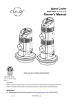
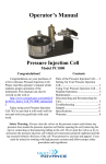
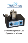
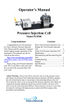
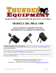
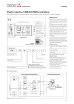
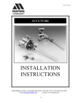
35B-1
GROUP 35B
FOUR-WHEEL
ANTI-LOCK BRAKE
SYSTEM (4ABS)
CONTENTS
GENERAL DESCRIPTION. . . . . . . . .
CONSTRUCTION DESCRIPTION . . .
SENSOR . . . . . . . . . . . . . . . . . . . . . . . . . . .
35B-2
35B-5
35B-5
ACTUATORS . . . . . . . . . . . . . . . . . . . . . . .
35B-6
ASC-ECU . . . . . . . . . . . . . . . . . . . . . . . . . .
35B-7
SYSTEM OPERATION . . . . . . . . . . . .
35B-9
35B-2
FOUR-WHEEL ANTI-LOCK BRAKE SYSTEM (4ABS)
GENERAL DESCRIPTION
GENERAL DESCRIPTION
.
The ABS (with EBD and brake assist) that ensures
directional stability and controllability during hard
braking has been equipped as a standard.
This ABS employs a 4-sensor system that independently controls the right and left wheels of front and
rear, and has the following features:
• Compared with the conventional model, by adding the information from the G and yaw rate sensor, master cylinder pressure sensor, and wheel
cylinder pressure sensor to the ABS control, the
braking performance and steering performance
when driving in high speed and on race circuits
have been improved so that the vehicle's high
athletic performance can be further demonstrated.
M2351000101059
*1
• EBD (Electronic Brake-force Distribution system) control that can provide ideal rear wheel
brake force has been employed.
• The magnetic encoder for wheel speed detection
has been installed instead of the rotor as the
wheel speed sensor.
• For wiring harness saving and secure data communication, CAN *2 bus has been adopted as a
tool of communication with another ECU.
NOTE: .
• *1: EBD (Electronic Brake-force Distribution)
• *2: For more details on CAN (Controller Area Network), refer to GROUP 54C P.54C-2.
• As with the active skid control (ASC), ABS is controlled by ASC-ECU.
.
SPECIFICATIONS
Item
Specifications
ABS control type
4 sensors
Wheel speed sensor
Magnetic encoder
Type
.
TSB Revision
Front
96 (N pole: 48, S pole: 48)
Rear
86 (N pole: 43, S pole: 43)
Semiconductor
35B-3
FOUR-WHEEL ANTI-LOCK BRAKE SYSTEM (4ABS)
GENERAL DESCRIPTION
CONSTRUCTION DIAGRAM
9
11
10
12
SERVICE
REQUIRED
6, 7, 8, 14
CHECK
5
4
3
13
1
2
1
2
AC708736 AB
TSB Revision
35B-4
FOUR-WHEEL ANTI-LOCK BRAKE SYSTEM (4ABS)
GENERAL DESCRIPTION
MAIN COMPONENTS AND FUNCTIONS
Parts name
Sensor
No. Functional description
Wheel speed sensor
1
Outputs the frequency pulse signal in proportion to the
rotation speed of each wheel to ASC-ECU.
Magnetic encoder for
wheel speed detection
2
When the magnetic encoder for wheel speed detection
(a plate on which north and south pole sides of the
magnets are arranged alternately) rotates, the wheel
speed sensor outputs frequency pulse signal in
proportion to each wheel speed.
Stop light switch
3
Outputs the signal indicating whether the brake pedal
is depressed or not to ASC-ECU.
G and yaw rate sensor
4
Detects the yaw rate and longitudinal/lateral
acceleration of a vehicle, then outputs the signal to
ASC-ECU via the CAN line.
Steering wheel sensor
5
Detects the steering angle of steering wheel, and
outputs the signal to ASC-ECU via the CAN bus line.
Master cylinder pressure 6
sensor
Integrated into the hydraulic unit, converts the signal of
brake fluid pressure in master cylinder to the voltage
value, then outputs the value to ASC-ECU.
Wheel cylinder pressure 7
sensor
Integrated into the hydraulic unit, converts the signal of
brake fluid pressure in wheel cylinder of each wheel to
the voltage value, then outputs the value to ASC-ECU.
Hydraulic unit
8
Drives the solenoid valve using the signal from
ASC-ECU, and controls the brake fluid pressure for
each wheel.
ABS warning light
9
Informs the driver of the system status by illuminating,
flashing, or turning off the warning light according to
the signal from ASC-ECU.
ABS warning display
10
Informs the driver of the system status by illuminating
or turning off the warning light according to the signal
from ASC-ECU.
Brake warning light
11
Used as the warning light for the parking brake, brake
fluid level, and EBD control. Informs the driver of the
system status by illuminating or turning off the warning
light according to the signal from ASC-ECU.
Brake warning display
12
Used as the warning light for the brake fluid level and
EBD control. Informs the driver of the system status by
illuminating or turning off the warning light according to
the signal from ASC-ECU.
Data link connector
13
Outputs the diagnostic trouble code and establishes
the communication with the scan tool.
ASC control unit (ASC-ECU)
14
Controls the actuators (described above) based on the
signals coming from each sensor.
Actuator
Controls the self-diagnostic functions and fail-safe
functions.
Controls diagnostic function (Compatible with scan
tool).
.
TSB Revision
FOUR-WHEEL ANTI-LOCK BRAKE SYSTEM (4ABS)
CONSTRUCTION DESCRIPTION
35B-5
SYSTEM CONFIGURATION
Refer to GROUP 35C − General Description
P.35C-2.
.
ABS ELECTRICAL DIAGRAM
Refer to GROUP 35C − General Description
P.35C-2.
CONSTRUCTION DESCRIPTION
SENSOR
M2351001000687
WHEEL SPEED SENSOR
FRONT
REAR
Rear wheel speed sensor
Front wheel speed sensor
Encoder for wheel speed detection
Encoder for wheel speed detection
AC507376AB
The wheel speed detecting section is a kind of a
pulse generator. It consists of the magnetic encoder
for wheel speed detection (plate on which north and
south pole sides of the magnets are arranged alternately) which rotates at the same speed of the wheel
and the wheel speed sensor (semiconductor sensor).
This sensor outputs frequency pulse signals in proportion to the wheel speed.
The front wheel speed detecting section consists of
the front wheel speed sensor mounted on the
knuckle and the magnetic encoder for wheel speed
detection which is press-fitted together with the oil
seal to the front wheel bearing. The rear wheel
speed detecting section consists of the rear wheel
speed sensor mounted on the knuckle assembly and
the magnetic encoder for wheel speed detection
which is press-fitted together with the oil seal to the
rear wheel bearing.
G AND YAW RATE SENSOR
This sensor is installed under the instrument panel center
lower, and detects the yaw rate as well as the lateral and longitudinal acceleration of the vehicle.
SRS-ECU
G&yaw rate sensor
AC613534AB
TSB Revision
35B-6
FOUR-WHEEL ANTI-LOCK BRAKE SYSTEM (4ABS)
CONSTRUCTION DESCRIPTION
STEERING WHEEL SENSOR
The steering wheel sensor is mounted to the column switch,
and detects the rotational angle of the steering wheel.
Steering wheel sensor
AC709400AB
ACTUATORS
M2351002000475
.
HYDRAULIC UNIT
As with the active skid control (ASC), ABS is controlled by ASC-ECU.
NOTE: For more information on the internal hydraulic
circuit of hydraulic unit, refer to GROUP 35C − System Operation P.35C-14.
.
ABS WARNING LIGHT, ABS WARNING
DISPLAY, BRAKE WARNING LIGHT,
BRAKE WARNING DISPLAY
The ABS system illuminates or flashes the ABS
warning light, ABS warning display, brake warning
light, or brake warning display under the following
conditions, and informs the driver of the ABS system
status.
ABS warning light, ABS warning display, brake warning light and brake warning display illumination
or flashing pattern
State
ABS warning
ABS warning
Brake warning Brake warning
light
display
light
display
Normal
Correct
−
−
−
−
Faulty
ABS failure
Illuminates
Illuminates
−
−
EBD failure
Illuminates
Illuminates
Illuminates
Illuminates
Actuator not
operated
−
−
−
−
Actuator operated
Flash (2Hz)
−
−
−
After actuator
operated*
Illuminates*
−
Illuminates*
−
When scan
tool is
connected
NOTE: .
• *: The ABS warning light and brake warning light
remain illuminated until the ignition switch is
turned to the LOCK (OFF) position.
TSB Revision
• When the brake fluid level in the brake fluid reservoir tank is at a specified value or less, or when
the parking brake lever is in the operating status,
the brake warning light illuminates.
35B-7
FOUR-WHEEL ANTI-LOCK BRAKE SYSTEM (4ABS)
CONSTRUCTION DESCRIPTION
ASC-ECU
• This ECU incorporates the ABS function, EBD
function, ASC function, and TCL function.
• By integrating ABS-ECU into the hydraulic unit,
no more wiring harnesses for sending signal that
operates the solenoid valve and pump motor is
required, assuring higher reliability.
• Self-diagnostic and memory functions are integrated into ASC-ECU. If any malfunction is
detected by the diagnostic function, ABS-ECU
activates a fail-safe function and illuminates the
ABS warning light and brake warning light*.
NOTE: *: The brake warning light is used as the
EBD control warning light.
M2351003000713
• ASC-ECU detects the vehicle deceleration speed
using the signals of the steering wheel sensor,
wheel speed sensor, G and yaw rate sensor,
master cylinder pressure sensor, and wheel cylinder pressure sensor to acquire the wheel rotation
status. At the same time, ASC-ECU estimates the
wheel slipping status based on the preprogrammed algorithm, and then controls the solenoid valve in the hydraulic unit so that the wheels
do not lock.
ABS HYDRAULIC PRESSURE CONTROL
.
ABS CONTROL CYCLE
Increase
Hold
Decrease
Wheel speed
Estimated vehicle speed
C
A
D
B
Actual vehicle speed
Brake pressure
a
e
d
b
c
AC506830AB
1. ASC-ECU calculates the speed and deceleration
of each wheel based on the signals from the
wheel speed sensors and G and yaw rate sensors
of four wheels, and estimates the vehicle speed of
at that time.
TSB Revision
35B-8
FOUR-WHEEL ANTI-LOCK BRAKE SYSTEM (4ABS)
CONSTRUCTION DESCRIPTION
2. When the brake is depressed, the brake fluid
pressure applied to the wheel cylinder increases,
and the wheel speed decreases. When the
difference between the wheel speed and vehicle
speed increases, and the vehicle deceleration
exceeds the specified value (Point A), ASC-ECU
determines that the wheels are about to be
locked. At this time, ASC-ECU reduces the brake
fluid pressure by outputting the pressure
decrease signal to the solenoid valves (IN, OUT).
(Between a and b)
3. When the vehicle deceleration and wheel speed
begin to recover, and when the vehicle speed
reaches the point B, ASC-ECU outputs the
pressure hold signal to maintain the wheel
cylinder fluid pressure. (Between b and c)
4. When the wheel speed deceleration recovers
further and passes the point C, ASC-ECU
determines that the wheel lock possibility has
been eliminated, and maintains the brake fluid
pressure by outputting the pressure increase
signal again. (Between c and d)
5. Brake fluid pressure is controlled through the
repetition of pressure increase and pressure hold.
(Between d and e)
6. When the wheel deceleration exceeds the
threshold again, ABS-ECU controls the brake fluid
pressure by repeating the cycle (Steps 2 to 5).
.
EBD FLUID PRESSURE CONTROL
EBD operating conceptual design
Braking force distribution
by EBD control
Ideal distribution curve when
seated by fixed persons
Rear braking force
Braking force distribution curve
by the existing proportioning valve
Ideal distribution curve when seated by one persons
Braking Force
Improved
Front braking force
AC208548AB
EBD control is activated within the lower slip ratio
area where ABS is disabled. EBD calculates the
vehicle deceleration and slip amount of the four
wheels based on the wheel speed sensor signal. If
the rear wheel speed differs from the vehicle speed
by a certain level or more, EBD boosts, holds, and
depressurizes the rear wheel control solenoid valve
in the hydraulic unit, and then adjusts the rear wheel
brake fluid pressure fairly close to an ideal distribution curve.
.
TSB Revision
FOUR-WHEEL ANTI-LOCK BRAKE SYSTEM (4ABS)
SYSTEM OPERATION
35B-9
INITIAL CHECK
CONSTANT CHECK
ASC-ECU performs the following initial checks using
the diagnostic functions. The ABS warning light illuminates for approximately 3 seconds (including the
initial check)* after the ignition switch is turned ON. If
any malfunction is detected, ABS-ECU continues illuminating the ABS warning light and disables the ABS
control.
NOTE: *: ABS warning light may keep illuminating
after the ignition switch is turned ON until the startup
vehicle speed reaches approximately 10 km/h. This
allows, as long as ASC-ECU retains any diagnostic
trouble code, which is related to the wheel speed
sensor malfunction or pump motor malfunction
recorded during the previous ignition ON status,
ASC-ECU to continue illuminating the ABS warning
light until it verifies that the malfunction for that code
is resolved (startup check).
ASC-ECU constantly checks the following items.
1. ASC-ECU
(1) Performs a self-diagnosis of ASC-ECU.
(2) Checks for abnormal output voltage of G and
yaw rate sensor, and detects an open or short
circuit in the G and yaw rate sensor.
(3) Checks the output voltage for G and yaw rate
sensor, and determines that a seizure has
occurred to the G sensor when the output
voltage exceeding the specified level
continues for a certain period or more.
2. ECU power supply
.
STARTUP CHECK
When the startup vehicle speed reaches approximately 10 km/h, ASC-ECU performs the following
checks.
1. Motor, solenoid valve check (Initial startup* only)
Turns ON the motor relay in ECU, and checks the
pump motor operation. At the same time,
ASC-ECU sequentially energizes each solenoid
valve for a very short period, and checks the valve
operation.
NOTE: *: Initial startup indicates the first startup
after the system has started.
2. Wheel speed sensor check
Checks if ECU power supply voltage is within the
operational range.
3. Wheel speed sensor
(1) Monitors the output current of the sensor
signal wiring harness, and checks for an
abnormal output current (open/short circuit).
(2) Checks if there is any wheel that does not
send pulse signal while the vehicle is in
motion.
(3) Checks for an input of abnormally higher or
lower wheel speed in relation to the vehicle
speed.
4. Pump motor, solenoid valve
Checks that the ASC-ECU output signal and the
operating statuses of pump motor and solenoid
valve agree with each other.
ABS-ECU checks if the wheel speed sensor
signal is received from all the wheel speed
sensors.
.
FAIL-SAFE AND DIAGNOSTIC FUNCTION
If any malfunction is detected by the diagnostic function, ASC-ECU illuminates the ABS warning light and
brake warning light, and disables the ABS and EBD
controls. In this case, the brake is operated as a normal brake.
Also, ASC-ECU has the following functions for easier
system checks.
• Diagnostic trouble code set
• Service data output
• Actuator test
SYSTEM OPERATION
Refer to GROUP 35C − System Operation P.35C-14.
TSB Revision
M2351004000374
NOTES