1
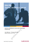
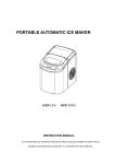
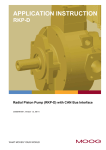
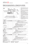
www.atos.com
Table G345-2/E
Plastic injection Z-ME-KZ-PS/GI controllers
Eurocard format, for electrohydraulic closed loop controls of injection in plastic presses
Z-ME-KZ-PS/GI
MAIN FUNCTIONS AND FEATURES
USER INTERFACE
SUPPLY 24V
VELOCITY REFERENCE
ENT
ESC
UP
INPUTS
PRESSURE/FORCE REF.
DWN
I1
I2
I3
I4
I5
I6
I7
I8
A1
A2
X1
X2
O1
O2
O3
O4
O5
O6
O7
A3
A4
A5
POSITION FEEDBACK
Real-time
fieldbus
Injection
process
PRESSURE FEEDBACK
AUXILIARY INPUT
P/Q
Alternated
control
RS232
Serial port
Velocity
control
DRIVER’S COMMAND
Enhanced
diagnostic
OUTPUTS
OK
MONITOR
PROFIBUS
AUXILIARY OUTPUT
Z-ME-KZ-PS/GI
Z-SW-PS
programming software
1
Z-SW-PS
SW
-PS
MODEL CODE
Z-ME
-
KZ
-
PS
/
*
GI
/
*
/
Electronic axis controller
in Eurocard format
*
Set code
Series number
Alternated position / velocity / force
control module
Injection process control
Serial communication interface for configuration
and monitoring function
2
Plastic injection controllers perform velocity
and force closed loop controls, according to
real time commands (analog or fieldbus)
generated by machine control unit (e.g.
PLC).
The controller receives position / pressure
feedbacks and generates reference signal to
the proportional valve which regulates the
hydraulic flow to the injection actuator.
The position feedback signal is software
selectable: SSI, incremental encoder, potentiometer or analog (voltage or current).
Remote pressure transducers have to be
remotely installed close to the injection
actuator and connected to the controller (see
section 5 ).
The machine electronic control unit manages
the injection process through dedicated digital commands or fieldbus communication.
Serial and Profibus (only for BP option) ports
are available on the front panel for controller
configuration and diagnostics.
Optional fieldbus interfaces:
- = standard without fieldbus interface
BC = CANopen communication interface
BP = PROFIBUS DP communication interface
Electrical Features:
• 4 digits front panel display to check and
change parameters as well as for diagnostics
• Front panel DB9 connector for serial programming interface
• Front panel test points for debug and
maintenance
• Eurocard format (DIN 41494 - Plug-in-units)
• CE mark according to EMC directive
Software Features:
• Internal generation of injection cycle
• Setting of axis’s dynamic response (PID) to
optimize the injection performances
• Monitoring of injection process
• Software selectable range of electronic
reference analog inputs: voltage or current
• Diagnostics of the injection status
• Intuitive graphic interface
• In field firmware update through standard
serial communication port
• Internal oscilloscope function
BLOCK DIAGRAM
DIGITAL CONTROLLER Z-ME-KZ-PS/GI
Z-SW-PS
SOFTWARE
INJECTION
PROCESS
VELOCITY
CONTROL
PID
FIELDBUS NETWORK
PLASTIC INJECTION SYSTEM
SERIAL PORT
PROPORTIONAL
VALVE
M
I
N
FIELDBUS
PRESSURE
CONTROL
MONITOR
PID
HYDRAULIC
INJECTION ACTUATOR
PRESSURE FEEDBACK
MACHINE
CENTRAL
UNIT
DIGITAL I/O
POSITION FEEDBACK
Note: Block diagram example with fieldbus interface.
G345
INJECTION PHASES
3
3.1 Injection - Velocity closed loop control with max pressure limitation
ENT
ESC
OK
Feedback
Reference
3.1 Injection
Pressure/Force
UP
DWN
I1
I2
I3
I4
I5
I6
I7
I8
A1
A2
X1
O1
O2
O3
O4
O5
O6
O7
A3
A4
A5
X2
M
Velocity
t
P
PROFIBUS
RS232
t
CONDITIONS
DRIVER
A
B
P
T
T
STATUS
Injection
ON
Force Transfer
OFF
Decompression
OFF
Injection phase starts when the machine control unit (e.g.
PLC) enables the command “Injection”. The controller
performs velocity closed loop profile according to the
external velocity reference, with a maximum force limitation during traversing. Machine control unit provides velocity step reference to the controller, which internally limits
acceleration and deceleration in order to avoid mechanicals stress during velocity variations
Position
t
3.2 Pack and Hold - Pressure closed loop control with max velocity limitation
ENT
ESC
OK
Feedback
Reference
3.2 Pack and Hold
Pressure/Force
UP
DWN
I1
I2
I3
I4
I5
I6
I7
I8
A1
A2
X1
O1
O2
O3
O4
O5
O6
O7
A3
A4
A5
X2
M
Velocity
t
Pack and Hold phase starts when the machine control unit
enables the command “Force Transfer” with “Injection”
condition active. The controller performs pressure/force
closed loop control with max velocity limitation to prevent
sudden forward actuator movements in the transition from
Injection to Pack and Hold phase
P
PROFIBUS
RS232
t
DRIVER
A
B
T
P
CONDITIONS
STATUS
Injection
ON
Force Transfer
ON
Decompression
OFF
Position
T
t
3.3 Pre-Decompression - Velocity open loop control
ENT
ESC
OK
Feedback
Reference
3.3 Pre-Decompression - optional phase
Pressure/Force
UP
DWN
I1
I2
I3
I4
I5
I6
I7
I8
A1
A2
X1
O1
O2
O3
O4
O5
O6
O7
A3
A4
A5
X2
M
Velocity
t
Pre-Decompression phase starts when the machine control unit enables the “Decompression” condition. The controller regulates in open loop the backward velocity of the
injection actuator according to the external command
signal (velocity reference)
P
PROFIBUS
RS232
t
DRIVER
A
B
P
T
T
CONDITIONS
STATUS
Injection
OFF
Force Transfer
OFF
Decompression
ON
Position
t
3.4 Back Pressure - Pressure closed loop control with max velocity limitation
ENT
ESC
OK
Feedback
Reference
3.4 Back Pressure
Pressure/Force
UP
DWN
I1
I2
I3
I4
I5
I6
I7
I8
A1
A2
X1
O1
O2
O3
O4
O5
O6
O7
A3
A4
A5
X2
M
Velocity
t
P
PROFIBUS
RS232
Back Pressure phase starts when the machine control unit
enables the command “Force Transfer” with “Injection”
condition not active. The controller performs force closed
loop control with max velocity limitation to prevent sudden
backward actuator movements in the transition from Pack
and Hold or Pre-Decompression phase to Back Pressure
ones
t
DRIVER
A
B
P
T
T
CONDITIONS
STATUS
Injection
OFF
Force Transfer
ON
Decompression
OFF
Position
t
3.5 Post-Decompression - Velocity open loop control
ENT
ESC
OK
Feedback
Reference
3.5 Post-Decompression - optional phase
Pressure/Force
UP
DWN
I1
I2
I3
I4
I5
I6
I7
I8
A1
A2
X1
X2
O1
O2
O3
O4
O5
O6
O7
A3
A4
A5
M
Velocity
t
P
RS232
PROFIBUS
t
DRIVER
A
B
T
P
T
CONDITIONS
STATUS
Injection
OFF
Force Transfer
OFF
Decompression
ON
Position
t
Post-Decompression phase starts when the machine control unit enables the “Decompression” condition. The controller regulates in open loop the backward velocity of the
injection actuator according to the external command
signal (velocity reference)
4
EXAMPLE OF INJECTION CYCLE WITH DIGITAL COMMANDS FROM MACHINE CENTRAL UNIT
PACK AND HOLD
INJECTION
BACK PRESSURE
DECOMP.
DECOMP.
COMMANDS
Injection condition
DI7 (1)
Force Transfer condition
DI3 (1)
Decompression condition
DI8 (1)
Pressure(Force)
Time
Velocity
Time
Position
Time
Feedback
Reference
Note: (1) see section 11 for digital inputs commands connection
Note: for controllers with BP or BC option the injection cycle is managed by fieldbus commands
5
PRESSURE / FORCE CONFIGURATION
For technical support about proportional valve selection and control electronic configuration, please contact Atos tech assistance at [email protected]
Alternated Velocity/Pressure Control - One pressure transducer
MACHINE
CONTROL UNIT
Alternated Velocity/Force Control - Two pressure transducers
MACHINE
CONTROL UNIT
INPUT
OUTPUT
ENT
ESC
OK
INPUT
M
OUTPUT
UP
DWN
I1
I2
I3
I4
I5
I6
I7
I8
A1
A2
X1
X2
OK
O1
O2
O3
O4
O5
O6
O7
A3
A4
A5
ENT
ESC
P
M
UP
DWN
I1
I2
I3
I4
I5
I6
I7
I8
A1
A2
X1
X2
O1
O2
O3
O4
O5
O6
O7
A3
A4
A5
P
P
CONTROLLER
CONTROLLER
DRIVER
Z-ME-KZ-PS/GI
RS232
PROFIBUS
DRIVER
Z-ME-KZ-PS/GI
A
RS232
B
PROFIBUS
T
P
T
Typical schemes used in injection molding machines designed for
high/medium density materials.
Proportional valves with V9 spool type (see section 6 ) should be used.
A remote pressure transducer has to be installed on the injection line of
the actuator.
T valve’s spool transducer
6
A
B
P
T
T
Typical schemes used in injection molding machines designed for
low density materials.
Proportional valves with linear spool type with zero overlap characteristics
is strictly recommended to obtain improved force control.
Two remote pressure transducers have to be installed on the actuator’s
ports; the actuator force is calculated by the pressure feedbacks (Pa - Pb).
M actuator’s position transducer
P
pressure transducer
SPECIAL SPOOL FOR INJECTION PROCESS
V9 main features:
- strong meter-in characteristic allows the pressure
control during the holding pressure and the plasticizing phases
- safety central position depressurizes the actuator
chambers
- large flow capability, required during the plasticizing phase, discharges big oil volumes from
injection actuators with low pressure drops and
also permits the contemporary oil suction from
tank
backward movements
(flow active)
depressuring
(pressure active)
forward movements
(flow or pressure active)
G345
7
CONTROLLER CHARACTERISTICS
Power supply (see 12.1)
Nominal: +24 VDC
Rectified and filtered: VRMS = 20 ÷ 32 VMAX (ripple max 10 % VPP)
Max power consumption
10 W
Position transducer
SSI, incremental encoder, potentiometer, analog
Input range :
voltage ±10 VDC
- input impedance: Ri > 100 kW
current 0 ÷ 20 mA - input impedance: Ri < 500 W
Output range :
voltage ±10 VDC @ max 10 mA
current 0 ÷ 20 mA @ max 500 W load resistance
Input range :
0 ÷ 5 VDC (OFF state), 16 ÷ 24 VDC (ON state), 5 ÷ 16 VDC (not accepted);
Input impedance: Ri > 10 kW
Digital Outputs (1)
Output range :
0 ÷ 24 VDC ( ON state > [power supply - 2 V] ; OFF state < 1 V ) @ max 30 mA
Enable input
Range : 0 ÷ 5 VDC (OFF state), 16 ÷ 24 VDC (ON state), 5 ÷ 16 VDC (not accepted); Input impedance: Ri > 10 kW
Fault output (1)
Output range : 0 ÷ 24 VDC ( no fault state > [power supply - 2 V] ; fault state < 1 V ) @ max 50 mA
Analog reference outputs
±10 VDC @ max 30 mA
Inceremental encoder power supply
+5 VDC @ max 100 mA
Alarms
Position transducer out of range, analog input out of range
Card format
Eurocard 100x160 mm (Plug-in unit DIN 41494)
Card rear connector
Male DIN EN 60603/G. Available frame snap connector type E-K-64M (see tech table G800) To be ordered separately
Operating temperature
0 ÷ +50 °C (storage -20 ÷ +70 °C)
Front panel dimensions
128,4 x 40 mm
Mass
Approx. 250 g
Electromagnetic compatibility (EMC)
According to Directive 2004/108/CE (Immunity: EN 50082-2; Emission: EN 50081-2)
Communication interface
Serial
Atos ASCII coding
CANopen
EN50325-4 + DS408
PROFIBUS
EN50170-2/IEC61158
Communication physical layer
not insulated
serial RS232
optical insulated
CAN ISO11898
optical insulated
RS485
Analog Inputs
Analog Outputs
Digital Inputs
Note: (1) external negative voltage not allowed (e.g. due to inductive loads)
8 TRANSDUCER CHARACTERISTICS
8.1
Position transducers
The accuracy of the velocity control is strongly dependent to the selected position transducer. Four different transducer interfaces are available on the
controller, according to the system requirements: potentiometer, analog signal, SSI, and encoder, see 8.3.
Transducers with digital interface (SSI and encoder) allow the user to get high resolution and accurate measures. Transducers with analog interface
(potentiometer and analog signal) grant simple and cost effective solutions.
8.2
Pressure transducers
The accuracy of the pressure/force controls is strongly dependent to the selected pressure transducers. Alternated pressure or force controls require to
install pressure transducers to measure the actual pressure values.
Pressure transducers allow easy system integration and cost effective solution for both alternated position/pressure and position/force controls (see tech
table G465 for pressure transducers details).
The characteristics of the remote pressure transducers must be always selected to match the application requirements and to obtain the best performances: transducer nominal range should be at least 115%÷120% of the maximum regulated pressure/force.
8.3
Transducers characteristics & interfaces - following values are just for reference, for details please consult the transducer’s datasheet
Position
Input type
Pressure/Force
Potentiometer
Analog
SSI
Incremental Encoder
Analog
±10 VDC
+24 VDC
+5 VDC / +24 VDC
+5 VDC / +24 VDC
+24 VDC
±10V
0 ÷ 10V 4 ÷ 20 mA
Serial SSI binary/gray
TTL 5Vpp - 150 KHz
±10 VDC 4 ÷ 20 mA
0,5 m/s
1 m/s
2 m/s
2 m/s
-
Max Resolution
< 0.4 % FS
< 0.2 % FS
1 mm
1 mm (@ 0.15 m/s)
< 0.4 % FS
Linearity error (2)
± 0.1% FS
< ±0.03% FS
< ± 0.01 % FS
< ± 0.001 % FS
< ±0.25% FS
Repeatability (2)
± 0.05% FS
< ± 0.005% FS
< ± 0.001 % FS
< ± 0.001 % FS
< ±0.1% FS
Power supply (1)
Controller Interface
Max speed
Notes: (1) power supply provided by digital controller
(2) percentage of total stroke
9 FRONT PANEL DESCRIPTION
10 FRONT PANEL VIEW
9.1 Keyboard and display
On the Z-ME-KZ-PS/GI front panel are available 4 function keys (ESC, ENT, UP,
DWN), and a numeric display (4 digits plus sign) to allow the user to view and
change the controller’s parameters as well as to display diagnostic messages.
The following parameters can be accessed (viewed or changed) via corresponding menu structure:
- command and actual values
- analog input / output values
- digital input / output status
- position sensor indication
- force / pressure sensor indication
Parameter’s changes of the configuration, control gains, trigger conditions, internal cycle, fault monitoring are not allowed via front panel operations.
Function Keys
Display
ENT
ESC
UP
OK Led
OK
Active Led
Digital Input Led
Digital Output Led
Auxiliary Led
9.2 LED indication
The led indications are used to display the internal status (Active, OK) of the controller or the status of the digital IO of the Z-ME-KZ-PS/GI. There are 22 led divided in four different types:
- internal controller’s status (Active - OK)
- digital input status (I1 ÷ I8)
- digital output status (O1 ÷ O7)
- software programmable led (A1 ÷ A5) for specific functions
DWN
O1
O2
O3
O4
O5
O6
O7
A3
A4
A5
I1
I2
I3
I4
I5
I6
I7
I8
A1
A2
X1
X2
Test Points
RS232 serial programming port
9.3 Test points
PROFIBUS
RS232
PROFIBUS-DP port (*)
The test points present on the controller front panel can be used to monitor the
actual position (X1) and the force / pressure (X2) value measured by the relevant
transducers. Both signals are referred to the analog ground (┴) pin. The two
signals are respectively connected to P_MONITOR+ (X1) and F_MONITOR+ (X2)
analog output present on the rear connector of the controller card. These signals
can be software set to show other signals available in the controller (see 12.7 and 12.8).
Z-ME-KZ-PS/GI
Z-ME-KZ
(*) only for BP option
9.4 Communication ports
On the front panel of the Z-ME-KZ-PS/GI is always present a serial RS232 port to program the controller by the Atos Z-SW software (see section 13 ). All
the functional parameters of digital controller, like internal reference generation, controller dynamics, IO configurations, can be easily set and optimized
by the user.
For BP or BC options, a second communication port dedicated to the selected fieldbus connection is present on the controller. For BP option the
PROFIBUS-DP port is located on the front panel of the Z-ME-KZ-PS/GI controller. For BC option the CANopen connection is located on the rear connector
of the Z-ME-KZ-PS/GI controller.
Through the fieldbus communication only the real-time parameters may be exchanged:
- position, velocity and force / pressure reference
- position, velocity and force / pressure feedback
- controller commands and status
- diagnostic / error messages
For more information about the front panel settings and fieldbus communication, please refer to the controller user manual.
11 ELECTRONIC CONNECTIONS - 64 PIN REAR CONNECTOR
f
d b
z
pin
f
d
b
z
2
DO 7
(O)
DI 1
(I)
nc
(I)
nc
4
SSI clock +
(D)
DI 2 (*)
(I)
nc
(I)
nc
6
SSI clock -
(D)
DI 3 Force Transfer
(I)
F_TR1 +
(I)
nc
2
4
6
8
8
SSI data + / Inc Ua1 (D)
DI 4 Jog +
(I)
F_TR1 -
(I)
nc
10
SSI data - / Inc /Ua1 (D)
DI 5
(I)
F_INPUT +
(I)
nc
10
12
12
Inc Ua2
(D)
DI 6 Jog -
(I)
F_INPUT -
(I)
nc
14
Inc /Ua2
(D)
DI 7 Injection
(I)
F_TR2 +
(I)
nc
16
Inc Ua0
(D)
DI 8 Decompression
(I)
F_TR2 -
(I)
nc
18
Inc /Ua0
(D)
ENABLE
(I)
P_TR +
(I)
nc
20
Inc +5VDC
(O)
DO 1
(O)
P_TR -
(I)
GND
22
nc
FAULT
(O)
V_INPUT +
(I)
DO 3
(O)
24
nc
nc
V_INPUT -
(I)
DO 4
(O)
26
nc
DO 2
P_MONITOR +
(O)
DO 5
(O)
28
CAN_GND
(F)
DO 6
(O)
30
CAN_L
(F)
32
CAN_H
(F)
14
16
18
20
22
24
26
(O)
28
nc
AGND
30
CONTROL_OUTPUT + (O)
VREF -10VDC
(O)
V+
(PS)
VREF +10VDC
(O)
V0
(PS)
32
rear view
F_MONITOR +
(O)
(I) Input - (O) Output - (D) Digital transducers - (PS) Power supply - (F) Fieldbus interface, only for BC option
(*) Digital Input status must be always disabled (OFF) - Do Not Connect
G345
12
SIGNAL SPECIFICATIONS
Atos digital controllers are CE marked according to the applicable directives (e.g. Immunity/Emission EMC Directive).
Installation, wirings and start-up procedures must be performed according to the prescriptions shown in table F003 and in the user manuals included in
the Z-SW programming software.
The electrical signals of the controller (e.g. monitor signals) must not be directly used to activate safety functions, like to switch-ON/OFF the machine’s
safety components, as prescribed by the European standards.
12.1 Power supply (V+ and V0)
The power supply must be appropriately stabilized or rectified and filtered: apply at least a 10000 mF/40 V capacitance to single phase rectifiers or a
4700 mF/40 V capacitance to three phase rectifiers.
The controller is protected against overloads by a internal safety fuse: 3,15 A Time-delay fuse.
12.2 Velocity reference input signal (V_INPUT+, V_INPUT-)
The controller allows to limit the axis velocity according to an external voltage or current reference input signal (V_INPUT+ and V_INPUT-). The analog
input is a differential input type.
The input range and polarity are software selectable within the maximum range ±10 VDC for voltage or 0 ÷ 20 mA for current; default setting is 0 ÷ 10 VDC.
Controller with fieldbus interface (BC or BP) can be software set to receive reference value directly by the machine control unit (fieldbus master); in this
case the analog reference input signal can be used for start-up and maintenance operations.
12.3 Pressure or force reference input signals (F_INPUT+,F_INPUT-)
For alternated position/force (or position/pressure) control the Z-ME-KZ-PS/GI receives a second analog voltage or current reference input signal
(F_INPUT+,F_INPUT-) dedicated to the force (or pressure) closed loop control. The analog input is a differential input type.
The input range and polarity are software selectable within the maximum range ±10 VDC for voltage or 0 ÷ 20 mA for current; default setting is 0 ÷ 10 VDC.
Controller with fieldbus interface (BC or BP) can be software set to receive reference value directly by the machine electronic control unit (fieldbus
master); in this case the analog reference input signals can be used for start-up and maintenance operations.
12.4 Position transducer input signal
A position transducer must be always directly connected to the controller: digital SSI (SSI clock+, SSI clock-, SSI data+, SSI data-), digital Encoder
(Inc Ua1, Inc /Ua1, Inc Ua2, Inc /Ua2,Inc Ua0, Inc /Ua0), potentiometer or a generic transducer with analog interface (P_TR+, P_TR-) can be used.
For transducers with analog interface the input range and polarity are software selectable within the maximum range ±10 VDC for voltage or 0 ÷ 20 mA for
current; default setting is 0 ÷ 10 VDC.
Refer to position transducer characteristics to select the transducer type that matches the specific application requirements (see 8.1).
12.5 Pressure transducer input signal (F_TR1+, F_TR1-, F_TR2+, F_TR2-)
Analog remote pressure transducers must be always directly connected to the controller.
One transducer must be connected in case of alternated position/pressure control; two transducers must be connected in case of alternated
position/force control.
Refer to pressure transducer characteristics to select the transducer type that mach the specific application requirements (see 8.2).
The input range and polarity are software selectable within the maximum range ±10 VDC for voltage or 0 ÷ 20 mA for current; default setting is 0 ÷ 10 VDC.
12.6 Control output signal (CONTROL_OUTPUT+)
The error signal processed by the control algorithms generates the control output signal (CONTROL_OUTPUT+) for the external driver of the proportional
valve which operates the hydraulic flow to the actuator.
The output range and polarity are software selectable within ±10 VDC (for voltage) or 0 ÷ 20 mA (for current) maximum range referred to the analog
ground (AGND); default setting is ±10 VDC.
12.7 Position monitor output signal (P_MONITOR+)
The controller generates an analog voltage output signal proportional to the actual axis position; the monitor output signal can be software set to show other
signals available in the controller (e.g. position analog reference, position fieldbus reference, position error).
The output polarity is software selectable within ±10 VDC maximum range referred to the analog ground (AGND); default setting is ±10 VDC.
The P_MONITOR+ signal is also present on the front panel at test point X1.
12.8 Pressure or force monitor output signal (F_MONITOR+)
The controller generates an analog voltage output signal proportional to the actual pressure or force applied to the actuator; the monitor output signals can be
software set to show other signals available in the controller (e.g. pressure/force analog reference, pressure/force fieldbus reference, pressure/force error).
The output polarity is software selectable within ±10 VDC maximum range referred to the analog ground (AGND); default setting is ±10 VDC.
The F_MONITOR+ signal is also present on the front panel at test point X2.
12.9 Enable Input Signal (ENABLE)
To enable the controller, a 24VDC voltage has to be applied on pin d18 referred to pin b28.
When the Enable signal is set to zero the controller can be software set to perform one of the following actions:
- move forward or backward in open loop - default setting
- maintain in closed loop a predefined actuator’s position (hold position)
- maintain the actuator actual position in close loop control
- disable the controller functioning (control output set to zero)
12.10 Fault output signal (FAULT)
Fault output signal indicates fault conditions of the controller (alarm active, reference or transducer signal cable broken, max error exceeded, etc.).
Fault presence corresponds to 0 VDC, normal working corresponds to 24 VDC (pin d22 referred to pin b28).
12.11 Power supply signal for potentiometer position transducer (VREF -10VDC, VREF +10VDC)
Power supply for potentiometer position transducer may be generated from the controller card using the VREF -10VDC and VREF +10VDC signal @ max 30 mA.
12.12 Power supply for incremental encoder position transducer (Inc +5VDC, GND)
Power supply for incremental encoder position transducer may be generated from the controller card using the +5VDC @ max 100 mA.
12.13 Digital input signals (DI1 - DI8)
Five pre-configured digital inputs (DI3, DI4, DI6, DI7, DI8) are dedicated to manage of the injection process, while two digital inputs (DI1, DI5) are used to
trigger a command or to read a system state. For DI1 and DI5 input by the Z-SW software, it is possible to set the polarity and to match a proper condition
within the following:
- start/stop/switch-over command in case of internal reference generation
- specific operative command for hydraulic axis mode (referencing mode, jog mode, automatic mode)
- jog command
- disable pressure / force alternated control
12.14 Digital output signals (DO1 - DO7)
Seven digital outputs can be used to generate digital signals useful to the system synchronization and for monitoring purpose. The digital outputs can be
configured in polarity and all the channels can be independently programmed by the Z-SW software.
Typically the digital outputs are used to:
- set alarm condition related with the hydraulic axis working phase
- identify a particular working condition to synchronize other machine functionalities
- signal target position reached
- signal pressure / force control active
- signal tracking error
12.15 CANopen communication signals - only for BC option
For controllers with CANopen communication interface, the connections are located on the rear connector: pin f28 (CAN_GND), pin f30 (CAN_L) and pin
f32 (CAN_H).
13 PROGRAMMING TOOLS - see tech table GS500
Valve's functional parameters and configurations, can be easily set and optimized using Atos Z-SW programming software connected via serial communication
port to the digital controller. Z-SW software is available in different versions according to the controllers’s communication interface: PS (Serial) Z-SW-PS,
BC (CANopen) Z-SW-BC and BP (PROFIBUS DP) Z-SW-BP.
For fieldbus versions, Z-SW software permits valve's parameterization through serial communication port also if the controller is connected to the central machine unit via fieldbus.
Full programming software, to be ordered separately :
Z-SW-*
DVD first supply
= software has to be activated via web registration at www.download.atos.com ; 1 year service included
Upon web registration user receive via email the Activation Code (software license) and login data to access personal Atos Download Area.
The software remains active for 10 days from the installation date and then it stops until the user inputs the Activation Code.
Z-SW-*-N DVD next supplies = only for supplies after the first; service not included, web registration not allowed
Software has to be activated with Activation Code received upon first supply web registration
Atos Download Area: direct access to latest releases of Z-SW software, manuals, USB drivers and fieldbus configuration files at www.download.atos.com
USB Adapters, Cables and Terminators, can be ordered separately
14 MAIN SOFTWARE PARAMETER SETTINGS
For a detailed descriptions of the available settings, wirings and installation procedures, please refer to the user manuals included in the Z-SW-* DVD
programming software:
Z-MAN-ME-KZ-GI - user manual for Z-ME-KZ-PS/GI
14.1 External reference and transducer parameters
Allow to configure the controller reference and transducer inputs, analog or digital, to match the specific application requirements:
- Scaling parameters
define the correspondence of these signals with the specific actuator stroke or force to be controlled
- Limit parameters
define maximum/minimum stroke and force to detect possible alarm conditions
- Homing parameters
define the startup procedure to initialize incremental transducer (e.g. encoder)
14.2 Position PID control dynamics parameters
Allow to optimize and adapt the position controller closed loop to the wide range of hydraulic system characteristics:
- PID (position)
each part of the position controller closed loop algorithm (proportional, fine positioning advanced integral, derivative, feed
forward, etc.) can be modified in order to match the application requirements
14.3 Multiple pressure/force PID control dynamics parameters
Allow to customize and adapt the pressure/force controller closed loop to each injection cycle phase:
- PID (pressure/force)
each part of the pressure/force controller closed loop algorithm (proportional, integral, derivative, feed forward, etc) can be
modified in order to match the phases requirements
14.4 Control output signal parameters
Allow to configure the controller command for the proportional valve which regulates the hydraulic flow to the actuator:
- Scaling parameters
define the correspondence of the command signal to the specific valve reference signal range
- Limit parameters
define maximum/minimum range to detect possible alarm conditions
14.5 Monitoring parameters
Allow to configure the controller monitoring function of the positioning error (difference between actual reference and feedback) and detects anomalous
conditions:
- Monitoring parameters maximum allowed errors can be set for both static and dynamic positioning phases, and dedicated waiting times can be set to
delay the activation of the alarm condition and relevant reaction (see 14.6)
14.6 Fault parameters
Allow to configure how the controller detect and react to alarm conditions:
- Diagnostics parameters define different conditions, threshold and delay time to detect alarm conditions
- Reaction parameters
define different actions to be performed in case of alarm presence (stop at actual or preprogrammed position, emergency
forward/backward, controller disabling, etc.)
14.7 Digital IO configuration
Allow to configure the controller’s digital inputs/outputs to trigger/generate signals from /for the external machine central unit:
- Polarity
define the signal active state
- Trigger condition
define the input state to run a predefined internal command (see 12.13)
- Output state
define the digital output based on the internal controller state (see 12.14)
14.8 Motion phases parameters
When the internal reference generation is active a pre-programmed cycle can be generated; start/stop/switch-over commands and reference generation
types parameters can be set to design a customized sequence of motion phases adapted to the specific application requirements.
G345
15 WIRING BLOCK EXAMPLES
15.1 External analog reference - potentiometer actuator transducer - 1 pressure transducer
Rear side connections
(1)
POWER SUPPLY
24VDC
ANALOG VELOCITY
REFERENCE
+
+
z30
ESC
ENT
UP
b26
b24
d18
DIGITAL ENABLE
ON=24VDC; OFF=0VDC
DIGITAL FAULT
ON=24VDC; OFF=0VDC
d30
z32
b22
OK
d22
DWN
I1
I2
I3
I4
I5
I6
I7
I8
A1
A2
O1
O2
O3
O4
O5
O6
O7
A3
A4
A5
VALVE REF.
ANALOG POSITION
MONITOR
b6
PRESSURE 1+
b8
PRESSURE 1-
b32
VREF +10VDC
b30
VREF -10VDC
b12
b18
P_TR+
FORCE TRANSFER DI 3
d6
b20
P_TR-
JOG+ DI 4
d8
b28
AGND
d32
ANALOG PRESSURE
MONITOR
ANALOG PRESSURE
REFERENCE
+
b10
JOG- DI 6
d12
INJECTION DI 7
d14
DECOMPRESSION DI 8
d16
X1
RS232
X2
PROFIBUS
d20
DO 1
d26
DO 2
(2)
O7
A3
A4
A5
b18
P_TR+
b20
P_TR-
b28
AGND
(3)
(1) For the valve driver electrical connection please refer to the specific technical table
(2) For the potentiometer position transducer connection please refer to transducer datasheet
(3) For the analog position transducer connection please refer to transducer datasheet
Z-ME-KZ-PS/GI
15.2 External reference - SSI actuator transducer - 2 pressure transducers - CANopen
Rear side connections
POWER SUPPLY
24VDC
(2) ANALOG VELOCITY
+
(2)
ANALOG FORCE
REFERENCE
z32
+
b22
+
b10
REFERENCE
ESC
DIGITAL ENABLE
ON=24VDC; OFF=0VDC
DIGITAL FAULT
ON=24VDC; OFF=0VDC
ENT
OK
b12
d22
DWN
I1
I2
I3
I4
I5
I6
I7
I8
A1
A2
X1
X2
O1
O2
O3
O4
O5
O6
O7
A3
A4
A5
b26
ANALOG POSITION
MONITOR
ANALOG FORCE
MONITOR
d32
PROFIBUS
RS232
d30
VALVE REF.
b6
PRESSURE 1+
b8
PRESSURE 1-
b14
PRESSURE 2+
b16
PRESSURE 2-
f4
SSI CLOCK+
f6
SSI CLOCK-
f8
SSI DATA+
b8
f10
SSI DATA-
b28
f32
CAN_H
f30
CAN_L
f28
CAN_GND
UP
b24
d18
(2)
(1)
z30
b28
AGND
(4)
O7
A3
A4
A5
PRESSURE 1+
AGND
(5)
(3)
(1) For the valve driver electrical connection please refer to
the specific technical table
(2) Only for start-up and maintenance operations
(3) CANopen fieldbus interface on rear connector
(4) For the SSI position transducer connection please refer to
transducer datasheet
(5) Pressure transducer connection with current signal output
Real-time
fieldbus
CANopen
INTERFACE
Z-ME-KZ-PS/BCGI
b6
15.3 internal reference generation - encoder actuator transducer - 1 pressure transducer - PROFIBUS-DP
Rear side connections
POWER SUPPLY
24VDC
(2) ANALOG VELOCITY
+
z30
+
b22
+
b10
REFERENCE
(2) ANALOG PRESSURE
REFERENCE
(2)
DIGITAL ENABLE
ON=24VDC; OFF=0VDC
DIGITAL FAULT
ON=24VDC; OFF=0VDC
ANALOG POSITION
MONITOR
ANALOG PRESSURE
MONITOR
z32
ESC
ENT
d30
VALVE REF.
b6
PRESSURE 1+
b8
PRESSURE 1-
f8
INC UA1
f10
INC /UA1
f12
INC UA2
f14
INC /UA2
f16
INC UA0
f18
INC /UA0
UP
b24
OK
b12
d18
d22
DWN
I1
I2
I3
I4
I5
I6
I7
I8
A1
A2
X1
X2
O1
O2
O3
O4
O5
O6
O7
A3
A4
A5
b26
d32
(3)
RS232
PROFIBUS
b28
AGND
Z-ME-KZ-PS/BPGI
12/14
(1)
f20
INC +5VDC
z20
GND
(4)
EXTERNAL
ENCODER
(1) For the valve driver electrical connection please refer to
the specific technincal table
(2) Only for start-up and maintenance operations
(3) PROFIBUS-DP fieldbus interface on front panel
(4) For the encoder position transducer connection please
refer to transducer datasheet