1
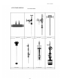
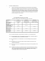
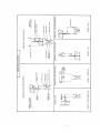
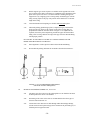
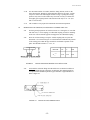
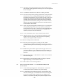
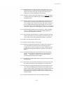
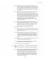
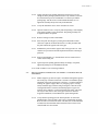
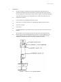
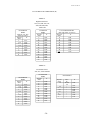
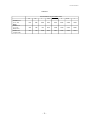
File No. 957:440-15 ACCUTUBE 10920 Madison Avenue · Cleveland, Ohio 44102 · (216) 281-1100 · FAX (216) 281-0228 e-mail: [email protected] web site: www.meriam.com -1- File No. 957:440-15 ACCUTUBE INSTALLATION INSTRUCTIONS CONTENTS PAGE ACCUTUBE MODEL NO. CONFIGURATOR................................................................3 ACCUTUBE MODELS .....................................................................................................4 1 SYSTEM CONSIDERATIONS.........................................................................................5 2 OPERATIONAL CONSIDERATIONS.............................................................................9 3 READOUT INSTRUMENTATION ..................................................................................9 4 INSTALLATION PROCEDURE ......................................................................................9 4.1 GENERAL REQUIREMENTS..................................................................................9 4.2 SERIES 10A, 11A, & 12A ......................................................................................10 4.3 SERIES 20T, 21T, 22L, 23L, 40H, 41H, 42H & 43H.............................................11 4.4 SERIES 24D & 25D ................................................................................................12 4.5 SERIES 33T INSTALLATION ..............................................................................13 4.6 PROBE REMOVAL................................................................................................15 4.7 SERIES 37L, 70H & 72H INSTALLATION..........................................................15 4.7.0 EQUIPMENT REQUIRED ........................................................................15 4.7.1 INSTALLATION – 1/2" AND 1" DIA. PROBES W / SOCKET DRIVE.....15 4.7.2 INSTALLATION – 1/2" AND 1" DIA. PROBES W / GEAR DRIVE .........17 4.7.3 INSTALLATION – 2-3/8" DIA. PROBES W / SOCKET DRIVE ...............18 4.7.4 INSTALLATION – 2-3/8" DIA. PROBES W / GEAR DRIVE....................20 4.7.5 SPECIAL DOUBLE-SUPPORT INSTRUCTIONS....................................21 4.7.6 RETRACTION PROCEDURE FOR SOCKET DRIVE UNITS..............22 4.7.7 RETRACTION PROCEDURE FOR GEAR DRIVE UNITS ...................23 4.8 DIRECT TRANSMITTER MOUNT HEADS WITH EQUALIZING VALVES...24 AND INTEGRAL RTD OPTION, SERIES 40H - 43H, 70H & 72H 4.9 SPECIAL APPLICATIONS (DUCTS/SADDLE CLAMPS/ROTATED HEAD)..25 5 OPERATIONS .................................................................................................................26 6 INTERCHANGEABILITY..............................................................................................27 7 MAINTENANCE & REPLACEMENT PARTS ............................................................28 8 TROUBLESHOOTING ..................................................................................................28 9 CALCULATIONS & FLOW COEFFICIENTS.........................................................29-31 -2- File No. 957:440-15 ACCUTUBE MODEL NUMBER CONFIGURATOR SERIES LINE SIZE PROBE DIA. (1) PROBE MATL. INSTRU. VALVES INSERT. VALVE THE FIRST THREE DIGITS IDENTIFY THE STYLE OF PROBE 10A = SCH 40 INLINE 11A = SCH 80 INLINE 20T = LOW PRESSURE INSERTION, SINGLE MOUNT 21T = LOW PRESSURE INSERTION, DOUBLE MOUNT 22L = HIGH PRESSURE INSERTION, SINGLE MOUNT 23L = HIGH PRESSURE INSERTION, DOUBLE MOUNT 24D = HIGH PRESSURE FLANGE, SINGLE MOUNT 25D = HIGH PRESSURE FLANGE, DOUBLE MOUNT 33T = LOW PRESSURE WET TAP 37L = HIGH PRESSURE WET TAP 40H = DIRECT XMITER MOUNT W / 3-VALVE, SINGLE MT 41H = DIRECT XMITER MOUNT W / 3-VALVE, DOUBLE MT 42H = DIRECT XMITER MT W / 3-VALVE & RTD, SINGLE 43H = DIRECT XMITER MT W / 3-VALVE & RTD, DOUBLE 70H = DIRECT XMITER MT W / 3-VALVE, WET TAP 72H = DIRECT XMITER MT W / 3-VALVE & RTD, WET TAP (2) NOMINAL LINE SIZE 0005 = 1/2" LINE 0007 = 3/4" LINE 0060 = 6" LINE 0080 = 8" LINE (2A) 0100 = 10" LINE 0300 = 30" LINE 1020 = 102" LINE 1440 = 144" LINE PROBE DIAMETER A = 1/2" B = 1" C = 2-3/8" (3) D = 3/8" E = 3/4" F = ALL INLINE SERIES 10A & 11A SENSOR MATERIAL 00 = 316SS PROBE WITH BRASS CONNECTION HEAD (SERIES 20T, 21T & 33T ONLY) 02 = CARBON STEEL (SERIES 10A & 11A ONLY) 03 = ALL 316SS PROBE (AVAILABLE IN ALL SERIES) 10 = BRASS BODY AND PROBE (SERIES 10A & 11A ONLY) 30 = PVC WITH THREADED PROCESS CONNECTIONS (SERIES 11A ONLY) 31 = PVC WITH PLAIN END PROCESS CONNECTIONS (SERIES 11A ONLY) SP = SPECIAL - CONSULT FACTORY (4) INSTRUMENT SHUTOFF VALVES, TYPE & MATERIAL XX = NONE 00 = BRASS (SERIES 10A, 20T, 21T & 33T); = BRONZE (SERIES 22L, 23L, 24D & 37L) 02 = CARBON STEEL 03 = 316 SS (ALL SERIES EXCEPT 40H-43H, 70H & 72H. CALLS OUT HEAD MAT'L FOR THESE) 04 = C.S. OS&Y TYPE (SERIES 22L, 23L, 24D, 25D & 37L ONLY) 05 = 316 SS OS&Y TYPE (SERIES 22L, 23L, 24D, 25D & 37L ONLY) 14 = PVC BALL VALVE (PVC 11A ONLY) SP = SPECIAL - CONSULT FACTORY (5) INSERTION VALVE, TYPE & MATERIAL XX = NONE REQUIRED 00= BRONZE BALL VALVE (33T ONLY) 02 = CARBON STEEL BALL VALVE (37L, 70H & 72H ONLY) 03 = 316 SS BALL VALVE (33T, 37L, 70H & 72H ONLY) 04 = C.S. OS&Y VALVE (37L ONLY) 05 = 316 SS OS&Y VALVE (37L ONLY) SP = SPECIAL - CONSULT FACTORY (6) MOUNTING, TYPE & MATERIAL XX = NONE REQUIRED 01 = STEEL SADDLE CLAMP (20T, 22L & 33T ONLY) 02 = 3000# C.S. THRED-O-LET WITH BRASS PACKING (20T, 21T & 33T ONLY) 03 = 3000# C.S. THRED-O-LET WITH 316 SS PACKING (20T, 21T, 22L, 23L, 33T, 37L, 40H, 41H, 42H, 43H, 70H & 72H) 04 = 316 SS THRED-O-LET WITH 316 SS PACKING (20T, 21T, 22L, 23L) NYLON PKG (33T) GRAFOIL PKG (37L, 70H & 72H) 06 = ROUND DUCT MOUNT HARDWARE, C.S. (20T, 21T, 22L, 23L ONLY) 07 = RECTANGULAR DUCT MOUNT HARDWARE, C.S. (20T, 21T, 22L, 23L ONLY) 08 = PVC THRED-O-LET (20T, 21T, 22L, 23L, 33T ONLY) 1C = 150# C.S. FLANGE (24D & 25D, SPECIAL 37L, 70H & 72H) 3C = 300# C.S. FLANGE (24D & 25D, SPECIAL 37L, 70H & 72H) 6C = 600# C.S. FLANGE (24D & 25D, SPECIAL 37L, 70H & 72H) 9C = 900# C.S. FLANGE (24D & 25D, SPECIAL 37L, 70H & 72H) 1S = 150# S.S. FLANGE (24D & 25D, SPECIAL 37L, 70H & 72H) 3S = 300# S.S. FLANGE (24D & 25D, SPECIAL 37L, 70H & 72H) 6S = 600# S.S. FLANGE (24D & 25D, SPECIAL 37L, 70H & 72H) 9S = 900# S.S. FLANGE (24D & 25D, SPECIAL 37L, 70H & 72H) SP = SPECIAL - CONSULT FACTORY (7) DRIVE MECHANISM FOR WET TAPS SC = SOCKET DRIVE GD = GEAR DRIVE -3-3- MOUNTING WET TAP DRIVE File No. 957:440-15 ACCUTUBE MODELS ACCUTUBE MODELS 10A and 11A 24D and 25D 20T and 21T 33T -4- 22L and 23L 37L Socket Drive 40H and 43H 37L Gear Drive File No. 957:440-15 1 SYSTEM CONSIDERATIONS 1.1 Selection of the proper location and position of the Accutube flow sensor within the piping system is important. The first consideration is to locate the Accutube with proper upstream and downstream straight pipe runs. This is required to assure a fully developed symmetrical flow profile at the Accutube. Accuracy can be affected if sufficient piping is not provided. Table 1 shows recommended straight run requirements with various types of upstream flow disturbances. For inline series sensors the straight pipe run must be of the same schedule/I.D. as the Accutube. TABLE 1 RECOMMENDED STRAIGHT RUNS OF PIPE (Upstream Length in Terms of Internal Diameter of Pipe - See Notes) UPSTREAM FLOW DISTURBANCE ONE ELBOW OR TEE TWO 90 BENDS IN SAME PLANE TWO 90 BENDS DIFF. PLANE REDUCERS OR EXPANDERS ALL VALVES (SEE NOTE 3) WITH STRAIGHTENING VANES 6-8 WITHOUT STRAIGHTENING VANES-IN-PLANE 8 - 10 8 - 10 12 - 15 10 - 12 WITHOUT STRAIGHTENING VANES-OUT-PLANE 24 - 28 8 - 10 8 - 10 8 - 10 10 - 12 24 - 28 24 - 28 Note 1: Downstream straight run of pipe should be a minimum of 4 to 5 internal diameters. Note 2: The values listed in Table 1 are acceptable for most applications. Additional lengths are recommended where precise measurements are desired. Note 3: Recommendations for valve disturbances are for non-throttling (fully open) position only. Note 4: Straightening vanes (where used) shall be installed 2 diameters downstream of the upstream flow disturbance. Note 5: Deviations from the above recommendations will normally not affect repeatability of the flow signal. Note 6: Combination of various types of fittings can cause severe flow distortion, the results of which are unpredictable. Installations with fitting combinations other than those listed above should be approached with caution. Flow straightening vanes are strongly recommended to insure accurate flow measurement. -5-5- File No. 957:440-15 1.2 Determine the position of the Accutube and indicating instrument with respect to the pipe. Selection of the entry location (i.e. in from top or bottom, etc.) is determined by considering the fluid in the pipe. Sections 1.2.1 through 1.2.4 give general requirements for Accutube position and installation, and specific recommendations for each general category of fluid (1.2.1-Liquid; 1.2.2-Gas; 1.2.3-Steam; 1.2.4-General Requirement). 1.2.1 LIQUID FLOW METERING 1.2.1.1 With liquid flow the readout instrument is normally located below the Accutube. This prevents air entrapment in the instrument lines. Figures 1.1 through 1.4 show recommended orientation for liquid flow. 1.2.1.2 See Section 1.2.4 General Interconnection Requirements. 1.2.1.3 Instrument lines should be properly sloped (1/2" per foot) without high points that may cause air entrapment. If this is not possible, air vent valves must be placed at any high points in piping. Trapped air is a frequent cause for measurement error with liquids. Refer to Figs. 1.1 thru 1.4. 1.2.1.4 The air vent valves should be bled on a regular basis during normal operation and upon restart after a system shutdown. 1.2.2 GAS FLOW METERING 1.2.2.1 Few restrictions apply to system arrangement in dry gas flow. Figures 1.1, 1.2 and 1.5 are recommended for simplicity in installation. 1.2.2.2 For installations where condensation or entrained liquids accumulate in the instrument piping, it is recommended that the instrument be mounted above the Accutube or install the Accutube in the top portion of the line. If mounting the instrument below the Accutube is necessary, then sediment traps and/or drain valves should be used as in Figure 1.6. 1.2.2.3 See Section 1.2.4 for General Interconnection Requirements. 1.2.3 STEAM FLOW APPLICATIONS 1.2.3.1 As in liquid flow, the indicator should be located below the Accutube. Figure 1.1 shows the recommended configuration. This configuration allows condensate to collect in instrument lines and finds its natural level within the Accutube. See Figure 1.4 for top entry (probe) in horizontal lines. 1.2.3.2 An installation in a vertical pipe should only be performed when a horizontal line location is not available. This installation should be as in Figure 1.2. A special "rotated head" Accutube is normally used. This permits side port connection, allowing installation similar to Figure 1.2. 1.2.3.3 See Section 1.2.4 for General Interconnection Requirements. -6-6- File No. 95 -7- File No. 957:440-15 The indicator must be placed far enough away from the Accutube to prevent thermal damage from line heat. Allow 2 ft. of uninsulated instrument piping for every 100 F of process temperature. 1.2.3.4 Slope the instrument lines to probe at an incline of approximately 1/2" per foot to prevent air entrapment. WARNING: DO NOT ATTEMPT TO FILL INSTRUMENT LINES IF SYSTEM CONNECTING LINES ARE UNDER PRESSURE. 1.2.3.5 Fill the instrument lines with water before connecting the Accutube or opening block valves. 1.2.3.6 Allow approximately 1/2 hour after system startup for condensate level to stabilize. Stabilization time may be reduced by section 1.2.3.5 above. 1.2.3.7 Special installation considerations may be necessary when Accutubes are used for steam applications where the differential pressure is less than 10" water column. 1.2.4 GENERAL INTERCONNECTION REQUIREMENTS 1.2.4.1 Instrument lines to the Accutube shall be as large as possible in liquid and steam applications. For Accutube with 1/2" NPT connections, 1/2" pipe or tubing is recommended. Accutubes with 1/8" NPT connections should use 1/4" pipe or tubing. 1.2.4.2 Use of the optional instrument shutoff valves at the Accutube head are recommended. 1.2.4.3 Use of a 3-valve manifold is recommended at the indicator to aid system startup and to ease indicator maintenance and calibration. 1.2.4.4 Where instrument-piping slopes are required, use 1/2" per foot minimum. 1.2.4.5 The length of the instrument lines does not affect accuracy. Long lines can, however, dampen the indicator response time. 1.2.4.6 Test the system for leaks after connecting instrumentation to assure that no leaks exist. 1.2.4.7 In situations where accumulation of sediment or condensation within the piping is possible, a system drain or pressure blow down should be performed on a regular basis. Valves are recommended for indicators/transmitters without drain valves/plug. -8- File No. 957:440-15 2 3 4 OPERATIONAL CONSIDERATIONS 2.1 The Accutube flow sensor is a bi-directional flow meter. It can measure flow in either direction. The Accutube head is labeled High and Low pressure as observed for normal flow directions. With reverse flow, the High-pressure signal will occur at the Lowpressure port and vice versa. Reverse flow measurement is as precise as forward flow. This unique feature allows measurement of flow that changes direction. Special consideration should be given to the indicating instrument. Instruments which allow positive and negative (zero center) differential pressure readings are best applied here. 2.2 Accutube probes have limits as to the maximum flow rate that can be tolerated without risking damage to the sensor. The limits are defined as the maximum allowable differential pressure. See the Accutube general catalog which lists the maximum allowable differential pressures for your Accutube model. 2.3 Installation of the Accutube in locations where significant pipe vibrations exist should be avoided. Double mount style Accutubes are recommended where vibration is a concern. READOUT INSTRUMENTATION 3.1 Many types of readout instrumentation can be used to measure the Accutube differential pressure. The most common types are manometers, dial gauge indicators, electronic transmitters/transducers or electronic gauges. Each type has its own installation and operational characteristics. Refer to manufacturer's manuals for installation instructions. 3.2 Mounting position can affect zero indication on certain types of instruments. In such cases, the zero setting should be adjusted after installation of the instrument. 3.3 When a mercury manometer is used with a steam or liquid flow a correction factor must be applied to the flow calculations. Refer to Handbook, File No. 957:081, for determining the correction factor. INSTALLATION PROCEDURE 4.1 GENERAL REQUIREMENTS 4.1.1 Prepare the surface of the pipe or duct where the Accutube is to be mounted. Proper preparation involves removal of scale, rust, paint and grease for proper welding of the threaded coupling. 4.1.2 Drill or burn a hole through the pipe at the mounting location. The hole should be 1/16" to 1/8" larger than the probe diameter as identified in Table 4. TABLE 4 PROBE DIAMETER RECOMMENDED DRILL SIZE 3/8 1/2 7/16 9/16 3/4 13/16 1 2-3/8 1-1/16 2-1/2 -9- File No. 957:440-15 4.1.3 Double support type sensors require a second hole on the opposite side of the pipe. Location of this hole is important as it establishes proper alignment of the probe with respect to the flow. A common method of locating the opposite support hole is by wrapping a piece of string totally around the pipe, with the string crossing square to the pipe. The position can be marked at 1/2 the total length of the string. 4.1.4 Center the threaded weld coupling over the hole and tack weld in place. 4.1.5 Thread the packing gland fitting in place (compression type), and insert the probe into the pipe. Observe the position of the probe assuring that it is perpendicular within the tolerance shown in Figure 4.1. If adjustments are required, remove the probe and packing, and thread a pipe into the threaded fitting a few feet long. With the leverage of the pipe force the threaded fitting into the proper position. DO NOT TRY TO USE THE ACCUTUBE AS A LEVER. DAMAGE TO THE PROBE AND/OR PACKING CAN RESULT! 4.1.6 Once alignment is verified, perform a final weld of the threaded fitting. 4.1.7 Re-assemble the packing and insert the Accutube as described in Section 4.3. FIGURE 4.1 ACCUTUBE PROBE POSITIONING (Maximum Allowable Misalignment) 4.2 INLINE FLOW SENSORS: SERIES 10A, 11A & 12A 4.2.1 The inline series flow sensors are flow-through devices in which the line must be interrupted for the device to be installed. 4.2.2 Positioning of the sensor is the same as recommended for the other types of sensors as listed in Section 1.0. 4.2.3 Connections to the main line are made through either threaded pipe fittings, solvent cement for PVC plain end type, hose connections for plain end types, or soldered joint for copper tube units. - 10 - File No. 957:440-15 4.2.4 4.3 Series 10A and 11A inline sensors are bi-directional devices. They can be installed with flow in either direction through the unit. The Series 12A must be installed with the balancing valve downstream of the metering section. INSERTION FLOW SENSORS, COMPRESSION FITTING: SERIES 20T, 21T, 22L, 23L, 40H, 41H, 42H & 43H 4.3.1 Perform the general preparation steps as outlined in Section 4.1.1 through 4.1.6. 4.3.2 Slide fitting nut onto the probe with the threaded end facing the tip of the probe. 4.3.3 Slide the ferrule onto the probe so that the angle of the taper slopes downward toward the probe tip. 4.3.4 With the fitting body already assembled and tightened onto the threaded coupling, insert the probe into the line. 4.3.5 Slide the ferrule into the fitting body. 4.3.6 Thread the nut onto the fitting body finger-tight. 4.3.7 Properly position the probe so that the High-pressure connection (side connection) is pointing upstream within the tolerances as shown in Figure 4.1. 4.3.8 Withdraw the probe tip from the opposite end of the pipe 1/16" for line size 12" and smaller, and 1/8" for larger lines sizes. This step properly locates the sensing port holes and allows for thermal expansion of the probe. 4.3.8.1 The Series 21T, 23L, 41H & 43H double support Accutubes include a specially machined support plug. Be sure that the flow sensor is fully inserted into this plug and not simply resting on top. Rotating the probe and/or the plug while inserting the probe will aid in alignment. Be sure to retighten the plug and provide clearance as listed in 4.3.8. 4.3.9 Tighten the nut with a wrench an additional number of turns as follows. Hold the fitting body with a second wrench to prevent the body from turning. It is helpful to mark the nut to facilitate counting the number of turns. CAUTION: DO NOT OVERTIGHTEN! P ROBE DAMAGE CAN RESULT FROM OVERTIGHTENING. Sealing turns from hand-tight required Stainless steel fittings on probe 3/8" through 1" O.D............................................1-1/4 turns Brass fittings on probe diameters 3/8" and 3/4".......................................................2-1/4 turns - 11 - File No. 957:440-15 4.4 4.3.10 For maximum number of remakes, mark the fitting and nut (scribe or ink) before disassembly. Remake by tightening until marks line up again. A slight torque rise will be felt indicating the ferrule is being re-sprung into sealing position. Only after several remakes may it become necessary to advance the nut slightly past original position. This advance need only be 10 - 20 (less than 1/3 of a hex flat). 4.3.11 The Accutube is now prepared for instrument connection and operation. INSERTION FLOW SENSORS, FLANGE MOUNT: SERIES 24D & 25D 4.4.1 Perform general preparation as listed in Sections 4.1.1 through 4.1.4. Note that with this series, a weld coupling, not a threaded coupling is used for mounting. In the case of Series 25D the opposite end support is still a threaded coupling. 4.4.2 Place the weld neck flange on top the welded coupling and verify that the dimension A is as shown in Figure 4.2. This dimension establishes the position of the sensing ports within the pipe and allows for thermal expansion of the probe. The allowable tolerance is + 1/16", -0". Probe Dia. 1/2" 1" 2-3/8" + 1/16 3-1/2 3-1/2 4-3/8 A -0 FIGURE 4.2 4.4.3 24D/25D MOUNTING HEIGHT FOR 150lb FLANGE Tack weld the weld neck flange onto the Weld-O-Let so that the four holes on the flange straddle the pipe centerline. An imaginary line drawn through any two adjacent holes should run parallel to pipe centerline or perpendicular to it. Refer to Figure 4.3. FIGURE 4.3 24D/25D FLANGE ORIENTATION - 12 - File No. 957:440-15 4.5 4.4.4 Place the gasket on top of the weld neck flange and insert the Accutube to verify alignment of the probe and clearance. Alignment of the probe must be within the limits shown in Figure 4.1. The probe tip should clear the inside wall of the pipe by 1/16" on 12" and smaller line sizes, and 1/8" on larger line sizes (this clearance will occur within the support plug on Series 25D (see 4.4.5). Adjust the position of the Weld -O-Let and weld neck flange, if necessary, to provide proper orientation of the probe to the pipe. Align the probe flange boltholes with those on the weld neck flange and verify that the flow direction arrow stamped on the probe flange points in the proper direction. 4.4.5 For Series 25D the end support must now be positioned. Assemble the support plug into the threaded coupling. With the Accutube properly positioned, slip the threaded coupling over the probe tip and engage the support plug. Tack weld the threaded coupling in place. 4.4.6 Complete the welding of the Weld-O-Let and the weld neck flange (also ThredO-Let in case of opposite side supported model 25D). 4.4.7 Again assemble gasket and insert probe in place observing flow arrow direction. 4.4.8 Use a flat washer with each nut and bolt. First hand-tighten each bolt. Use a criss-cross or star pattern to tighten bolts. Check bolt tightness 24 hours after installation. 4.4.9 The Accutube is now prepared for instrument connection and operation. LOW PRESSURE WET TAP: SERIES 33T 4.5.1 Verify that the operating pressure and temperature are within the published limit of the Accutube, probe valves, and mounting assembly. Refer to Table 5. 4.5.2 Prepare the pipe surface for welding and tack weld the Thred-O-Let to the pipe. Verify alignment of the Thred-O-Let and finish the weld (see Section 4.1). 4.5.3 Assemble the support nipple (3/4" probes), chain hook and the insertion valve. Pipe sealant/dope is recommended on all pipe threads on the mounting assembly. Be sure that the insertion valve is in the fully open position. Be sure the chain hook is in place between the Thred-O-Let and the insertion valve. 4.5.4 Assemble the packing gland fitting onto the valve. The fitting need only be hand tightened and the ferrule need not be in place at this time. 4.5.5 Slide the punch through the fitting until it touches the pipe (diameter of the guide punch must be the same diameter as the Accutube). Specially machined punches and drills are required. These are available from Meriam. 4.5.6 Impact the punch to leave the impression on the pipe to aid in starting the drill. 4.5.7 Remove the punch and the packing gland fitting from the insertion valve. 4.5.8 Insert the drill through the insertion valve and reassemble the packing ferrule and nut around the drill shank. NOTE: The tapered end of the ferrule slips into the packing gland fitting body. - 13 - File No. 957:440-15 4.5.9 Lightly wrench-tighten the nut in place. Double check that all connections are tight and the insertion valve is fully open. 4.5.10 Mount the drill motor onto the drill and penetrate the pipe. The mounting assembly is now pressurized. 4.5.11 Retract the drill bit until it stops against the packing gland fitting and disassemble the drill motor from the drill bit. 4.5.12 Close the valve. 4.5.13 Slowly loosen the packing gland fitting to vent any pressure. Remove drill bit. 4.5.14 Assemble the reducing bushing (on 3/4" probe only) and cage pipe onto the insertion valve. 4.5.15 Assemble the pipe coupling onto the end of the cage pipe. 4.5.16 Assemble the packing gland fitting onto the pipe coupling. Be sure that the ferrule is in place with the taper end into the body of the fitting and the nut loose on the fitting body. All other joints should be wrench-tight. 4.5.17 Insert the Accutube probe into the packing gland fitting and slide down until the tip meets the insertion valve. 4.5.18 Lightly wrench-tighten the compression nut onto the Accutube probe. 4.5.19 Attach the safety chain to the head of the Accutube probe and to the chain hook located on the bottom side of the insertion valve. There should be little slack in the chain. This chain is an imperative safety measure to prevent the Accutube probe from accidentally being forced out of the assembly under pressure. 4.5.20 Verify that both instrument valves are fully closed. 4.5.21 Open the insertion valve fully. The entire system is again pressurized including the Accutube probe. Any leakage at the compression gland fitting can be corrected by further tightening the packing gland nut. 4.5.22 Manually push the probe in through the mounting assembly until the tip touches the opposite wall of the pipe. 4.5.23 Retract the probe 1/16" on line sizes 12" and less, and 1/8" for larger line sizes. This measure properly locates the sensing port holes and allows for thermal expansion of the probe. Align the probe so that the side head connection points into the flow. 4.5.24 Tighten the nut on the packing gland fitting two turns from the hand-tight/light wrench position for final sealing/holding capability. DO NOT OVER TIGHTEN! PROBE DAMAGE CAN RESULT FROM OVERTIGHTENING. 4.5.25 Readjust the chain position so that the chain is taut in this fully inserted position. - 14 - File No. 957:440-15 4.6 4.7 4.5.26 Verify the alignment of the probe head with respect to the pipe line. The side pressure port should point directly upstream. Refer to Figure 4.1 4.5.27 The Accutube is now ready to be placed into operation. PROBE REMOVAL 4.6.1 Close the high and Low-pressure instrument valves. 4.6.2 Disconnect or modify line connections to head to allow probe removal. 4.6.3 As a precaution, hold the probe in place and adjust the safety chain to allow 2 links of slack. 4.6.4 Still holding the probe loosen the packing gland fitting nut slowly until the probe can be withdrawn. 4.6.5 Withdraw the probe until the chain tightens. Retighten the packing nut. 4.6.6 Gently attempt to close the insertion valve. If the probe prevents if from closing, adjust the chain to allow 2 additional links of slack. Remove the probe further and again attempt to close the valve. Repeat this as necessary. 4.6.7 With the valve closed, there is still residual pressure in the upper portion of the assembly. This can be relieved by venting either or both of the valves on the Accutube head. 4.6.8 The probe can now be fully removed. HIGH PRESSURE WET-TAP: SERIES 37L, 70H & 72H 4.7.0 EQUIPMENT REQUIRED: 4.7.0.1 Accutube probe with all wet tap mounting hardware. 4.7.0.2 Instrument valves (1/2" NPT) to be assembled onto the probe. 4.7.0.3 Pressurized drilling equipment - suggested source is Mueller Co. (Decatur, Ill.) Model D-5 or DH-5 with necessary drill holder and adapter nipple to attach to 3/4" FNPT for the 1/2" diameter probe, 11/4" FNPT for the 1" diameter probe, and 3" - 150 lb. flanges for the 23/8" diameter probe. See Table 4 for drill size required. 4.7.0.4 Welding Equipment. 4.7.0.5 Standard pipe wrenches and hex wrenches. 4.7.1 INSTALLATION PROCEDURE - 1/2" AND 1" DIAMETER PROBES WITH SOCKET DRIVE 4.7.1.1 Verify that the operating pressure and temperature are within the Accutube probe, and valve limitations. Refer to Table 5. 4.7.1.2 In determining probe installation, a vertical probe position, either above or below the pipe is recommended for 12" line size and greater due to the assembly weight extending to the side. Support of the - 15 - File No. 957:440-15 assembly weight is required for horizontal probe position on larger line sizes. 4.7.1.3 Prepare the pipe surface for welding. Tack weld the Thred-O-Let in place and verify alignment. Refer to General Installation, Sections 4.1.3 through 4.1.6. 4.7.1.4 Assemble the close nipple onto the Thred-O-Let. The close nipple is a special design nipple that serves as a drill guide and a support for the Accutube probe. 4.7.1.5 Assemble the insertion valve onto the close nipple. Final position of the valve should be such that the stem of the valve is parallel to the centerline of the pipe. This assures clearance of the valve handle with the insertion/retraction rods. 4.7.1.6 Attach the drilling equipment to the insertion valve. Drill the hole through the wall. Operate the pressure drilling equipment in accordance with manufacturer's instructions. 4.7.1.7 After the drill has penetrated pipe, withdraw the spindle on the drill and close the insertion valve. The assembly is pressurized. Vent pressure by opening the vent valve or by loosening the drilling attachment. 4.7.1.8 Remove the drill from the insertion valve and in its place assemble the cage pipe. 4.7.1.9 Assemble the packing gland housing onto the other end of the threaded cage pipe. Final position of this housing after it is securely threaded in place should be such that the holes on the insertion flange straddle the pipe centerline. This position determines the proper orientation of the Accutube. 4.7.1.10 Assemble the packing rings (Grafoil) into the bore of the packing housing. The ring must be handled with care. A broken ring is not reusable. Substitution of alternate type packings will affect pressure/temperature ratings of the assembly. 4.7.1.11 Assemble the cylindrical shape follower atop the packing rings and into the packing housing. 4.7.1.12 The retainer is now placed atop the follower and secured loosely in place with the packing gland socket head cap screws. Do not tighten the screws at this point. 4.7.1.13 Assemble the instrument valves onto the Accutube probe head. 4.7.1.14 Assemble the insertion/retraction rods and nuts onto probe. The rods slip through the hole on the insertion bar and extend 2" out the top. A single nut is assembled to each side of the insertion bar and tightened so that the rod is secured in place. Loosely assemble the upper drive nut on the insertion rod up to the lower lock nut. This is done for both rods. 4.7.1.15 Insert the probe tip into the packing gland assembly and slide it until the probe tip contacts the inside of the valve. As this is done, the insertion/retraction rods must be guided through the proper holes on - 16 - File No. 957:440-15 the insertion flange of the packing housing. The head of the Accutube during this procedure should be oriented so that the flow arrow agrees with the flow direction within the pipe. During the initial insertion of the probe tip into the packing housing, use care not to damage the packing rings. Assemble the lower drive nuts with washers onto the insertion/retraction rods. Thread the nuts upward until the washers contact the insertion flange. 4.7.1.16 Lightly snug the packing gland socket head cap screws just enough to set the packing in place and remove any clearances. Turn the hex socket head cap screws each 1-1/4 turns to pre-load the packing rings. Turn the screws a small amount alternately so as to tighten the assembly slowly and evenly from both sides. 4.7.1.17 Verify the instrument valves on the Accutube head are closed. 4.7.1.18 Open the insertion valve. Verify all joints and packing are sealed tightly as the entire assembly is now pressurized. The packing assembly can be tightened further if required. 4.7.1.19 Insert the probe into pipeline by turning the lower drive nut counter clockwise to pull the Accutube probe into the line. Both lower drive nuts should be turned alternately so as to prevent uneven loading and jamming of the Accutube assembly. Use this procedure until the probe touches and stops on the opposite side of the pipe. 4.7.1.20 Withdraw the probe from the opposite end of the pipe wall 1/16" on 12" line size and less, or 1/8" on larger line sizes. This clearance is a provision for thermal expansion allowances and assures centering port holes. 4.7.1.21 Again inspect the packing gland assembly for leakage. If required, tighten the packing screws an additional amount. 4.7.1.22 The Accutube is now in working condition. 4.7.2 INSTALLATION PROCEDURE- "1/2" AND 1" DIAMETER PROBES WITH GEAR DRIVE Follow steps 4.7.1.1 through 4.7.1.8. Then proceed with the following steps. 4.7.2.1 Assemble the packing gland housing assembly onto the other end of the threaded cage pipe. Final position of this housing after it is securely threaded in place should be such that the holes on the insertion flange straddle the pipe centerline. This position determines the proper orientation of the Accutube. 4.7.2.2 Assemble the packing rings (Grafoil) into the bore of the packing housing. The ring must be handled with care. A broken ring is not reusable. Substitution of alternate type packings will affect pressure/temperature ratings of the assembly. 4.7.2.3 Assemble the cylindrical shape follower atop the packing rings and into the packing housing. - 17 - File No. 957:440-15 4.7.2.4 The retainer is now placed atop the follower and secured loosely in place with the packing gland socket head cap screws. Do not tighten the screws at this point. 4.7.2.5 Assemble the instrument valves onto the Accutube probe head. 4.7.2.6 Insert the probe tip into the packing gland assembly. During the initial insertion, use care not to damage the packing rings. Slide the probe through the packing until the probe tip contacts the inside of the closed insertion valve. During this procedure the Accutube head should be oriented so the flow arrow agrees with the flow direction within the pipe. Raise the threaded rods by turning the crank counter clockwise until the rods protrude through the insertion bar. Assemble threaded rods and insertion bar with nuts. 4.7.2.7 Lightly snug the packing gland socket head cap screws just enough to set the packing in place and remove any clearances. Turn the hex socket head cap screws each 1-1/4 turns to pre-load the packing rings. Turn the screws a small amount alternately so as to tighten the assembly slowly and evenly from both sides. 4.7.2.8 Verify the instrument valves on the Accutube head are closed. 4.7.2.9 Open the insertion valve. Verify all joints and packing are sealed tightly as the entire assembly is now pressurized. The packing assembly can be tightened further if required. 4.7.2.10 Remove locking rod from crank handle. 4.7.2.11 Insert the probe into pipeline by turning the crank handle counterclockwise to pull the Accutube probe into the line. Use this procedure until the probe touches and stops on the opposite side of the pipe. 4.7.2.12 Withdraw the probe from the opposite side of the pipe wall 1/16" on 12" line size and less, or 1/8" on larger line sizes. This clearance is a provision for thermal expansion allowances and assures centering of port holes. 4.7.2.13 Position crank handle so ¼" threaded hole is visible on lower insertion bar. Insert locking rod. 4.7.2.14 Again inspect the packing gland assembly for leakage. If required, tighten the packing screws an additional amount. 4.7.2.15 The Accutube is now in working condition. 4.7.3 INSTALLATION PROCEDURE - 2-3/8" DIAMETER PROBES WITH SOCKET DRIVE 4.7.3.1 Verify that the operating pressure and temperature are within the Accutube probe and valve limitations (see general catalog). 4.7.3.2 In determining probe installation position a vertical position either above or below the pipe is recommended for 24" line sizes and greater because the assembly weight extends to the side. Support of the assembly is required for horizontal probe position on larger line sizes. - 18 - File No. 957:440-15 4.7.3.3 Weld the Weld-O-Let in place in the pipe. The Weld-O-Let is to be positioned so that it is perpendicular to the centerline of the pipe and square to the surface of the pipe. The Weld-O-Let has a special designed I.D. to guide and support the drill and probe. 4.7.3.4 Assemble a weld neck flange onto the Weld-O-Let. Tack weld in place so that the flange holes straddle the pipe centerline. Verify alignment and finish the weld. 4.7.3.5 Assemble the insertion valve onto the flange with a gasket in place and fasten with bolts. Final position should be such that the stem of the valve is parallel to the centerline of the pipe. This assures clearance of the valve handle with the insertion/retraction rod. Use a flat washer with each bolt and nut. First hand-tighten each bolt. Use a criss-cross or star pattern to tighten bolts. Check tightness 24 hours after installation. 4.7.3.6 Attach the drilling equipment to the insertion valve. Drill size should be 2-1/2" in diameter. Operate the pressure drilling equipment in accordance with manufacturer's instructions. 4.7.3.7 After the drill has penetrated the pipe, withdraw the spindle on the drill and close the insertion valve. The assembly is pressurized. Open vent valve on drill or slowly loosen the drilling assembly to vent pressure. 4.7.3.8 Remove the drill from the insertion valve. 4.7.3.9 Weld the weld neck flange to the cage pipe. 4.7.3.10 Weld the packing gland housing onto the opposite end of cage pipe. A 1/16" gap must be left inside the socket of the housing prior to welding. The two insertion rod holes in the lower insertion bar of the packing gland housing must straddle the bolt holes in the weld neck flanges. 4.7.3.11 Assemble the packing rings (Grafoil) into the bore on the packing housing. The rings must be handled with care. A broken ring is not reusable. Substitution of alternate type packings will affect pressure/temperature ratings of the assembly. 4.7.3.12 Assemble the cylindrical shape follower atop the packing rings into the packing housing. 4.7.3.13 The retainer is now placed atop the follower and secured loosely with the socket head cap screws. Do not tighten the screws at this point. 4.7.3.14 Assemble the packing gland housing/extension subassembly onto the valve with the remaining gasket located between the flanges. Final position of this assembly, when bolted in place should be such that the holes on the lower insertion bar straddle the pipe centerline. This position determines the proper orientation of the Accutube probe when assembled in place. 4.7.3.15 Assemble the instrument valves onto the Accutube probe head. - 19 - File No. 957:440-15 4.7.3.16 Assemble the insertion/retraction rods and nuts onto the probe. The rods slip through the hole on the upper insertion bar and extend 2" out at the top. A single nut is assembled to each side of the upper insertion bar and tightened so that the rod is locked in place. Loosely assemble the upper drive nut on the insertion rod up to the lower lock nut. This is done for both rods. 4.7.3.17 Insert the probe tip into the packing gland assembly and slide it until the probe tip contacts the insertion valve. As this is done, the insertion/retraction rods must be guided through the proper holes on the lower retraction bar of the packing housing. The head of the Accutube during this procedure should be oriented so that the flow arrow points in the direction of flow. During the initial insertion of the probe tip into the packing housing, use care not to damage the packing rings. Assemble the lower drive nuts with washers onto the insertion/retraction rods. Thread the nuts upward until the washers contact the insertion flange. 4.7.3.18 Lightly snug down the packing gland socket head cap screws just enough to set the packing in place and remove any clearances. Turn the hex socket head cap screws an additional 1-1/2 turns to pre-load the packing rings. Turn the screws a small amount alternately so as to tighten the assembly slowly and evenly from both sides. 4.7.3.19 Verify the instrument valves on the Accutube are closed. 4.7.3.20 Open the insertion valve. Verify all joints and packing is sealed tightly as the entire assembly is now pressurized. The packing assembly can be tightened further if required. 4.7.3.21 Insert the probe into the pipe. This is done by turning the lower drive nut (counterclockwise when looking down at the probe) to pull the Accutube into line. Both lower drive nuts should be turned alternately so as to prevent uneven loading and jamming of the Accutube assembly. Use this procedure until the probe touches the opposite side of the pipe. 4.7.3.22 Withdraw the probe from the opposite end of the pipe wall 1/8". This clearance is a provision for thermal expansion. 4.7.3.23 Again inspect the packing gland assembly for leakage. If required, tighten the packing screws an additional amount. 4.7.3.24 The Accutube is now in working condition. 4.7.4 INSTALLATION PROCEDURE - 2 3/8" DIAMETER PROBES WITH GEAR DRIVE Follow steps 4.7.3.1 through 4.7.3.15. Then proceed with the following steps. 4.7.4.1 Insert the probe tip into the packing gland assembly. During the initial insertion, use care not to damage the packing rings. Slide the probe through the packing until the probe tip contacts the inside of the insertion valve. During this procedure the Accutube head should be oriented so the flow arrow agrees with the flow direction within the pipe. Raise the threaded rods by turning the crank counter clockwise until the rods protrude through the insertion bar. Assemble threaded rods and insertion bar with nuts. - 20 - File No. 957:440-15 4.7.4.2 Lightly snug down the packing gland socket head cap screws just enough to set the packing in place and remove any clearances. Turn the hex socket head cap screws an additional 1-1/2 turns to pre-load the packing rings. Turn the screws a small amount alternately so as to tighten the assembly slowly and evenly from both sides. 4.7.4.3 Verify the instrument valves on the Accutube are closed. 4.7.4.4 Open the insertion valve. Verify all joints and packing is sealed tightly as the entire assembly is now pressurized. The packing assembly can be tightened further if required. 4.7.4.5 Remove locking rod from crank handle. 4.7.4.6 Insert the probe into the pipe by turning the crank handle counter clockwise to pull the Accutube into the line. Use this procedure until the probe touches the opposite side of the pipe. 4.7.4.7 Withdraw the probe from the opposite side of the pipe wall 1/8". This clearance is a provision for thermal expansion and assures centering of port holes. 4.7.4.8 Position crank handle so ¼" threaded hole on lower insertion bar is visible. Insert locking rod. 4.7.4.9 Again inspect the packing gland assembly for leakage. If required, tighten the packing screws an additional amount. 4.7.4.10 The Accutube is now in working condition. 4.7.5 SPECIAL DOUBLE-SUPPORT WET-TAP MODEL 37L WITH SOCKET OR GEAR DRIVE 4.7.5.1 Double support type sensors require a second hole through the opposite side of the pipe. Location of this hole is critical as it establishes proper alignment of the probe with respect to the flow. A common method of locating the opposite support hole is by wrapping a piece of string totally around the pipe, with the string crossing the center line of the existing drilled hole at each end, and running square to pipe. The position can be marked at 1/2 the total length of the string. This work can only be done with no flow in the pipe. If the flow cannot be stopped for installation, contact Meriam for special arrangements. 4.7.5.2 Verify that the operating pressure and temperature are within the published limit of the Accutube, probe valves, and mounting assembly. Refer to Table 5 for maximum values. The data sheet of the individual Accutube lists the maximum insertion/retraction flow values. These values should never be exceeded. - 21 - File No. 957:440-15 4.7.5.3 Double support wet tap Accutubes include a specially machined insertion cone on the end of the probe. Be sure that the flow sensor is fully inserted into the opposite side support plug and not simply resting on top. Rotating the probe and/or the plug while inserting the probe will aid in alignment. Be sure to retighten the plug and provide clearance as described in 4.7.3.20 to 4.7.3.24 for socket drive wet taps or as described in 4.7.2.12 to 4.7.2.15 for gear drive wet taps. 4.7.5.4 All other instructions for the standard models apply. Job #_______________________________ Item # __________ Model # _____________________________________ Maximum Insertion/Retraction Flow Rate __________ 4.7.6 RETRACTION PROCEDURE 1/2", 1" AND 2-3/8" DIAMETER PROBES WITH SOCKET DRIVE 4.7.6.1 Close both instrument valves on the probe head. 4.7.6.2 Vent/depressurize the instrument connection lines and disconnect from the probe valves. 4.7.6.3 Retract the probe by rotating the lower drive nuts in a clockwise direction looking down from the probe head. Rotate each of the nuts a small amount alternately so that the probe is forced out evenly from both sides. If the pipe line pressure is not high enough to force the probe out of the wet tap assembly as the nuts are rotated, use the upper drive nuts to force the probe out. If the upper drive nuts are used, the lower drive nuts should be unthreaded down the run rod an inch away from the flange. 4.7.6.4 Continue the retraction of the probe until the lower drive nuts are positioned on the thread rod 1" from the end of the thread rod. NEVER UNTHREAD THE LOWER DRIVE NUTS FROM THE ROD UNTIL 4.7.7.6 IS COMPLETE! 4.7.6.5 Close the insertion valve. 4.7.6.6 Depressurize the wet tap assembly by cracking open the instrument valves. A short burst of line fluid will escape from the valves as the wet tap assembly depressurizes. 4.7.6.7 Loosen the packing gland assembly cap screws. - 22 - File No. 957:440-15 4.7.6.8 The Accutube may be left in this position (properly supported) prepared for future insertion or for removal from the wet tap assembly. There are two methods of removing the probe from the wet tap assembly. 4.7.6.8.1 Withdraw the probe completely out of the packing gland assembly and set aside. or 4.7.6.8.2 With the probe still in the wet tap assembly, unthread the cage nipple from the valve (unbolt the flanges in the case of 2-3/8" probe diameter models), treating the cage pipe, packing gland assembly and probe as an assembled unit. When the nipple is removed from the valve, the entire assembly can be simply lifted and removed. This procedure allows removal of probe in situations where minimum overhead clearance is available. 4.7.7 RETRACTION PROCEDURE ½", 1" AND 2 3/8" DIAMETER PROBES WITH GEAR DRIVE 4.7.7.1 Close both instrument valves on the probe head. 4.7.7.2 Vent / depressurize the instrument connection lines and disconnect from the probe valves. 4.7.7.3 Remove locking rod from crank handle. 4.7.7.4 Retract the probe by rotating the crank handle clockwise. 4.7.7.5 Continue the retraction of the probe until the threaded rods reach their mechanical stop. 4.7.7.6 Insert locking rod. 4.7.7.7 Close the insertion valve. 4.7.7.8 Depressurize the wet tap assembly by cracking open the instrument valves. A short burst of line fluid will escape from the valves as the wet tap assembly depressurizes. 4.7.7.9 Loosen the packing gland assembly cap screws. 4.7.7.9.1Withdraw the probe completely out of the packing gland assembly and set aside. or 4.7.7.9.2With the probe still in the wet tap assembly, unthread the cage nipple from the valve (unbolt the flanges in the case of 2-3/8" probe diameter models), treating the cage pipe, packing gland assembly and probe as an assembled unit. When the nipple is removed from the valve, the entire assembly can be simply lifted and removed. This procedure allows removal of probe in situations where minimum overhead clearance is available. 4.8 ACCUTUBES WITH DIRECT DP TRANSMITTER MOUNT INSTRUMENT HEAD, INSERTION MODELS 40H - 43H AND WET TAP MODELS 70H & 72H - 23 - File No. 957:440-15 4.8.1 MODELS 40H, 41H & 70H WITH DIRECT DP TRANSMITTER MOUNT HEAD 4.8.1.1 Refer to previous sections of this manual for Accutube-to-process pipe installation instructions. 4.8.1.2 The direct mount instrument head is designed to allow standard industrial DP transmitters to be bolted directly onto the Accutube head. Any transmitter with 2 1/8" center-to-center high and Low-pressure connections can be used. Height of heads is 2.42". Gaskets are supplied with the order. Transmitter mounting bolts (by customer) should be 7/16"-20 UNF × 2 ¾" length. 4.8.1.3 The integral 3-valve equalizing manifold facilitates transmitter isolation and equalization needs. 4.8.2 MODELS 42H, 43H & 72H WITH DIRECT DP TRANSMITTER MOUNT HEAD AND INTEGRAL RTD 4.8.2.1 Refer to previous sections of this manual for Accutube-to-process pipe installation instructions. 4.8.2.2 The direct mount instrument head is designed to allow standard industrial DP transmitters to be bolted directly onto the Accutube head. Transmitter with 2 1/8" center-to-center High and Low pressure connections can be used. Gaskets are supplied with the order. Transmitter mounting bolts (by customer) should be 7/16"-20 UNF × 2 ¾" length. 4.8.2.3 The integral 3-valve equalizing manifold facilitates transmitter isolation and equalization needs. Operation is the same as any 3-valve equalizing manifold. 4.8.2.4 The integral 100 ohm platinum RTD is shipped fully installed into the internal thermal well. Flexible SS sheath protects RTD wiring outside the Accutube. Wire termination at the receiver device (typically a smart multivariable transmitter) is left to the customer. A 5/16" -24 UNF × 1/8" tube compression fitting is supplied to complete the RTD wiring protection. This transition fitting secures the flexible SS sheath to the receiver's ½" FNPT conduit connection. 4.8.2.5 The RTD can be serviced or replaced, when necessary, without process shut down or removal of the head-mounted transmitter. The internal thermal well is completely sealed from the process. To remove the RTD, simply disconnect the RTD wiring at the receiver device and then disconnect the flexible SS sheath at the receiver device and at the Accutube head. The RTD can be pulled from the internal thermal well by the lead wires. Replacing a failed RTD is accomplished by feeding the platinum tip down the internal thermal well until it stops. By first measuring the distance from the Accutube head to the center of the process pipe and comparing to the length of wire inserted, the installer can judge whether the RTD tip has reached the bottom of the well. Reattach the flexible SS sheath and wire the new RTD to the receiver terminations to complete the service. - 24 - File No. 957:440-15 4.9 SPECIAL APPLICATIONS 4.9.1 Ducts The mounting technique for circular and rectangular ducts is most frequently the same as used for pipe in which a threaded coupling is welded in place. In instances where the duct wall is too thin to permit welding, a sheet metal flange option is available for bolt mounting. The flange is to be used with a user provided gasket or sealant between the flange and the duct. The surface of the duct where the gasket lays must be cleaned prior to application. All other standard instructions remain unchanged. This type of mounting is limited to pressures below 3 PSI. 4.9.2 Saddle Clamps Saddle clamps are used in applications where welding is not desired or possible. Saddle clamp mounting is accomplished by preparing the area around the hole that has been drilled. The gasket on the saddle clamp is placed around the hole and the unit is then bolted in place. It is important to bolt the saddle clamp as tightly as possible without damage to the pipe. All other instructions for the standard models apply. 4.9.3 Rotated Head When mounting an Accutube in a vertical steam or liquid line, it is recommended that a rotated head be used. This head is rotated 90 clockwise with respect to the standard head orientation (Figure 1.2). The rotation prevents false differential pressure that would otherwise be created due to the interior construction of the Accutube instrument head. - 25 - File No. 957:440-15 5 OPERATION 5.1 5.2 Once the Accutube is installed in the proper location and the instrument lines are installed to the indicator, the unit is prepared for operation. Operation of the Accutube involves setting valves in the proper sequence. Refer to Figure 5.1 in the following steps. Verify that the operating pressure and temperature are within the Accutube and valve limitations (see Table 5). Close Accutube valves A and B and start up the system. 5.3 Open valves C, D, and E on the three valve manifold (the indicator should read zero). 5.4 Open valves A and B. 5.5 Close valve E. 5.6 5.7 5.8 For liquid applications, open and bleed off air at any points where vent valves have been included. The Accutube is now in operation. In most cases the system can be shut down and turned on again without performing the startup sequence. For liquid applications, air venting should be done on a regular basis and also upon system restarts. On steam installations a stabilization period of 1/2 hour may sometimes be required FIGURE 5.1 TYPICAL VALVE ARRANGEMENT - 26 - File No. 957:440-15 TABLE 5 ACCUTUBE PRESSURE/TEMPERATURE LIMITATIONS MAXIMUM PRESSURE PSIG ACCUTUBE SERIES 10A/11A Steel, brass & copper 316 SS 20T/21T 22L/23L, 40H/41H, 42H/43H 24D/25D(1) 150# flange 33T(2) 37L, 70H, 72H (2) AT (3) 250 1000 1500 250 1500 285 150 1000 TEMPERATURE F 250 max 750 max 100 400 max 800 max 100 190 max 400 max (4) (1) Pressure / temperature on flanged series are governed by the flange rating. Flange rating options have higher capacity. (2) Wet tap assembly rating is also limited by insertion valve rating. (3) Consult factory where pressure or temperature exceeds either allowable maximum. (4) For maximum temperature up to 800º F, request welded cage pipe to packing assembly joint. Standard unit used Teflon tape and limits temperature to 400º F 6 INTERCHANGEABILITY 6.1 6.2 Accutube flow sensors can be conveniently interchanged between different measuring points. 6.1.1 Accutubes can be used to measure any type of fluid (liquid, gas and steam). The fluid must be compatible with the probe material and must be single phase. Multi-phase fluids such as gases with a significant amount of entrained liquids or liquids with significant entrained gases may not be accurately measured. 6.1.2 Any Accutube can be interchanged between pipes as long as the inside diameters are the same and the pressure rating of the probe and/or valves are not exceeded. The sensing port spacing is designed for specific inside pipe diameter. Use of the Accutube in pipe with the inside diameter different from its design inside diameter will result in measurement errors. Packing Fitting Reusability The packing fitting can be made and remade a number of times, however, the compression ferrule becomes permanently crimped onto the Accutube probe shaft after the first assembly. The ferrule is not removable. The ferrule can be assembled into different fitting bodies of the same make. - 27 - File No. 957:440-15 7 MAINTENANCE AND REPLACEMENT PARTS 7.1 Cleaning Accutube performance is generally not sensitive to dirt and film buildup. However, if contamination can build up to the point where internal or port hole blockage is threatened, then precautions must be taken to prevent this. One method commonly used is occasional probe removal for thorough cleaning. Purging systems are also used which on regular intervals inject air or fluid through the probe into the pipe line system, thus flushing out the probe interior. A pressure source and a system of control valves are required to do this. 7.2 Replacement Parts Accutube probes are completely welded sealed units for greatest integrity and reliability. No parts within the probe are replaceable. Mounting hardware and accessory parts can be obtained from the factory as replacement parts. 8 TROUBLESHOOTING 8.1 Should measurement problems occur with an Accutube probe, the following is a check list of possible causes: 8.1.1 Probe Position: Verify orientation of probe as stated in Section 1.0. 8.1.2 Upstream/Downstream Piping: Verify proper straight pipe run is as recommended in Section 1.0. (Table 1) 8.1.3 Pipe I.D.: Verify the inside diameter is nominally the same as that for which the probe is designed (standard product is Schedule 40 on 20" line size and less, and Standard Weight for larger line size). 8.1.4 Flow Magnitude and Direction: Verify that the reference source for expected flow is accurate. 8.1.5 Indicator Calibration: Verify indicator accuracy. 8.1.6 Indicator Scale: In installations where the scale is calibrated in flow units for specific flowing conditions, verify operating conditions agree with scale design conditions. Correction factors may be necessary (see File No. 957:081). 8.1.7 Air Entrapment: In liquid and steam applications, air trapped in high pockets of instrument piping can cause erratic/erroneous signals. 8.1.8 Blockage: Internal blockage will give an incorrect or no flow indication. - 28 - File No. 957:440-15 9 FLOW CALCULATIONS Flow Equations* 1. Any Liquid 2 Q(GPM) = 5.668 × K × Di × ∆ P/Sf 2. Steam or Any Gas** 2 Q(lb/Hr) = 359.1 × K × Di × 3. Any Gas ×∆P P×∆P (T + 460) × Ss 2 Q(SCFM) = 128.8 × K × Di × Differential Pressure Equations* 1. Any Liquid 2 Q × Sf 2 4 ∆P (In. WC) = K × Di × 32.14 2. Steam or Any Gas** Q 2 2 4 ∆P (In. WC) = K × D i × × 128,900 3. Any Gas 2 Q × Ss × (T + 460) 2 4 ∆P (In. WC) = K × Di × P × 16,590 Technical Notations The following notations apply: ∆ P = Differential pressure expressed in inches of water column Q = Flow expressed in GPM, SCFM of PPH as shown in equation K = Flow coefficient - See table 9.1 & 9.2 Di = Inside diameter of line size expressed in inches - For Inline Series see Table 9.3 For square and rectangular ducts use Di = 4 × Height × Width P = Static Line pressure (psia) T = Temperature in degrees Fahrenheit (plus 460 =Rankine) = Density of medium in pounds per cubic foot Sf = Liquid Sp. Gr. (density of liquid at flowing temperature / density of water at 60F) Ss = Gas Sp. Gr. (MWgas / MWair) *Consult Flow Handbook F/N 957:081 For Equation Derivation and for correction factors for precise calculations. **Use of Accutubes on steam applications generating less than 10" wc differential pressure at normal flow rate is not recommended. Reducing pipe size at the meter location may resolve this potential problem. - 29 - File No. 957:440-15 ACCUTUBE FLOW COEFFICIENT (K) TABLE 9.1 High Pressure Series 22L, 23L, 24D, 25D, 37L, 40H, 41H, 42H, 43H, 70H & 72H 1/2" DIAMETER PROBE (SER. 22L, 23L, 24D, 25D & 37L ONLY) Pipe Size K Inches 2 0.557 2 1/2 0.598 3 0.645 3 1/2 0.630 4 0.656 5 0.656 6 0.662 8 0.673 10 0.682 1" DIAMETER PROBE Pipe Size K Inches 6 0.647 8 0.678 10 0.657 12 0.677 14 0.665 16 0.691 18 0.678 20 0.705 24 0.708 30 0.664 36 0.663 42 0.672 48 0.673 60 0.685 2 3/8" DIAMETER PROBE (SER. 24D, 25D & 37L ONLY) Pipe Size K Inches 14 0.603 16 0.618 18 0.628 20 0.634 24 0.645 30 0.671 36 0.652 48 0.733 >60 0.670 TABLE 9.2 Low Pressure Series 20T, 21T, 33T & INLINE 3/8" DIAMETER PROBE Pipe Size K Inches 1 0.517 1 1/4 0.583 1 1/2 0.580 2 0.638 2 1/2 0.617 3 0.665 3 1/2 0.661 4 0.672 5 0.671 6 0.706 8 0.665 10 0.696 3/4" DIAMETER PROBE Pipe Size K Inches 6 0.706 8 0.686 10 0.676 12 0.683 14 0.698 16 0.688 18 0.689 20 0.686 24 0.789 30 0.720 36 0.757 42 0.697 - 30 - INLINE SERIES Pipe Size Inches 1/2 3/4 1 1 1/4 1 1/2 2 2 1/2 3 Series No. 10A and 11A " " " " " " " K 0.394 0.455 0.514 0.584 0.601 0.657 0.688 0.701 File No. 957:440-15 TABLE 9.3 1/2 SERIES 10A (C.S., 316, Brass) SERIES 11A (C.S., 316, Brass, PVC) SERIES 10A (Copper Tube) 3/4 Inside Diameter (Di) For Inline Series 1 1-1/4 1-1/2 2 2-1/2 3 .622 .824 1.049 1.380 1.610 2.067 2.469 3.068 .546 .742 .957 1.278 1.500 1.939 2.323 2.900 .527 .750 1.000 1.250 1.481 1.957 2.435 2.907 - 31 - File No. 957:440-15 10920 Madison Avenue · Cleveland, Ohio 44102 Telephone: (216) 281-1100 · FAX (216) 281-0228 - 32 -