1
SERVICE MANUAL
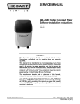
WS-500 Water Softening System
Installation Instructions
WS-500
- NOTICE This Manual is prepared for the use of trained Hobart Service
Technicians and should not be used by those not properly
qualified.
This manual is not intended to be all encompassing. If you have
not attended a Hobart Service School for this product, you should
read, in its entirety, the repair procedure you wish to perform to
determine if you have the necessary tools, instruments and skills
required to perform the procedure. Procedures for which you do
not have the necessary tools, instruments and skills should be
performed by a trained Hobart Service Technician.
The reproduction, transfer, sale or other use of this Manual,
without the express written consent of Hobart, is prohibited.
This manual has been provided to you by ITW Food Equipment
Group LLC ("ITW FEG") without charge and remains the property
of ITW FEG, and by accepting this manual you agree that you will
return it to ITW FEG promptly upon its request for such return at
any time in the future.
A product of Hobart Service
701 S. Ridge Ave Troy, OH 45374
F25405 Rev. A (0913)
WS-500 Water Softening System Installation Instructions
TABLE OF CONTENTS
GENERAL INFORMATION WS-500 . . . . . . . . . . . . . . . . . . . . . . . . . . . . . . . . . . . . . . . . . . . . . . . . . . . . . . . . . . . . . . . . . . . . . . . . . 3
GENERAL WS-500 . . . . . . . . . . . . . . . . . . . . . . . . . . . . . . . . . . . . . . . . . . . . . . . . . . . . . . . . . . . . . . . . . . . . . . . . . . . . . . . . . . . . . 3
BY PASS OPTIONS . . . . . . . . . . . . . . . . . . . . . . . . . . . . . . . . . . . . . . . . . . . . . . . . . . . . . . . . . . . . . . . . . . . . . . . . . . . . . . . . . . . . . . . . 4
BY- PASS VALVE KIT WS-500 . . . . . . . . . . . . . . . . . . . . . . . . . . . . . . . . . . . . . . . . . . . . . . . . . . . . . . . . . . . . . . . . . . . . . . . . . 4
BY- PASS VALVING WS-500 . . . . . . . . . . . . . . . . . . . . . . . . . . . . . . . . . . . . . . . . . . . . . . . . . . . . . . . . . . . . . . . . . . . . . . . . . . . 8
INSTALLATION . . . . . . . . . . . . . . . . . . . . . . . . . . . . . . . . . . . . . . . . . . . . . . . . . . . . . . . . . . . . . . . . . . . . . . . . . . . . . . . . . . . . . . . . . . . 10
INSTALLATION WS-500 . . . . . . . . . . . . . . . . . . . . . . . . . . . . . . . . . . . . . . . . . . . . . . . . . . . . . . . . . . . . . . . . . . . . . . . . . . . . . . 10
BRINE DRUM SETTINGS FOR WS-500 . . . . . . . . . . . . . . . . . . . . . . . . . . . . . . . . . . . . . . . . . . . . . . . . . . . . . . . . . . . . . . . 12
DISC REPLACEMENT . . . . . . . . . . . . . . . . . . . . . . . . . . . . . . . . . . . . . . . . . . . . . . . . . . . . . . . . . . . . . . . . . . . . . . . . . . . . . . . . . . . . 14
DISC REPLACEMENT WS-500 . . . . . . . . . . . . . . . . . . . . . . . . . . . . . . . . . . . . . . . . . . . . . . . . . . . . . . . . . . . . . . . . . . . . . . . . 14
DISC SELECTION . . . . . . . . . . . . . . . . . . . . . . . . . . . . . . . . . . . . . . . . . . . . . . . . . . . . . . . . . . . . . . . . . . . . . . . . . . . . . . . . . . . . . . . . 16
DISC SELECTION WS-500 . . . . . . . . . . . . . . . . . . . . . . . . . . . . . . . . . . . . . . . . . . . . . . . . . . . . . . . . . . . . . . . . . . . . . . . . . . . . 16
© HOBART SERVICE 2013
F25405 Rev. A (0913)
Page 2 of 16
WS-500 Water Softening System Installation Instructions - GENERAL INFORMATION WS-500
GENERAL INFORMATION WS-500
GENERAL WS-500
Disconnect the
electrical power to the machine and
follow lockout / tagout procedures.
1.
Determine location to install equipment. Make
sure the unit will be on a flat surface.
2.
If sand, silt, or turbidity is present, install a
separate prefilter.
NOTE: Sediment filtration is recommended before
the water softener, particularly in areas with known
sediment issues or on a private water supplies.
NOTE: If the peak flow rate required is unknown, a
prefilter with a minimum of 1.25" connections should
be used. Filters with 5 micron nominal ratings should
be considered the standard in food service
applications.
3.
If the optional by-pass valve kit is being installed,
follow steps listed under BY- PASS VALVE KIT
WS-500 . If bypass valve kit is not being installed
proceed to BY- PASS VALVING WS-500.
Page 3 of 16
F25405 Rev. A (0913)
WS-500 Water Softening System Installation Instructions - BY PASS OPTIONS
BY PASS OPTIONS
BY- PASS VALVE KIT WS-500
Disconnect the
electrical power to the machine and
follow lockout / tagout procedures.
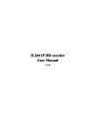
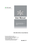
1.
To install by-pass valve determine which port on
the by-pass valve (Port A or Port B) to plumb the
raw water connection to.
Fig. 3
4.
Remove the by-pass valve handle by pulling it
away from the by-pass valve body.
Fig. 1
2.
Determine which port on the by-pass valve (Port
C or Port D) to connect the softener.
Fig. 4
5.
The five position valve has two installation
configuration options. Photo below shows the
crossover and parallel configurations as the
valve is shipped.
NOTE: When installing the five position valve - be
certain to select the proper mode and install
configuration (parallel or crossover).
Fig. 2
3.
Verify the by-pass valve is in the by-pass
position. Turn by-pass handle to reveal yellow
by-pass segment.
F25405 Rev. A (0913)
Page 4 of 16
WS-500 Water Softening System Installation Instructions - BY PASS OPTIONS
Fig. 7
Fig. 5
6.
Locate patch decal provided with by-pass valve
kit.
7.
Remove patch decal from paper lining and apply
to body of the by-pass valve based on the specific
installation using BY- PASS VALVE DECAL
TABLE.
NOTE: For use in A-D or B-D configuration, it will be
necessary to cut patch.
NOTE: When installing a plastic component in line, it
is recommended that grounding straps be put in place
before the lines are actually cut to ensure the ground
is never broken.
9.
Prepare plumbing by roughing in.
10. Connect the inlet/outlet adapters to the plumbing.
Solder or glue adapters to pipe as applicable.
NOTE: Do not solder adapters while in the by-pass
valve.
NOTE: Care should be taken during the installation
process to assure that solder flux does not come in
contact with the media tanks, the control module, and
related components.
Patch Decal
8.
Align the handle with the shaft until handle slides
onto shaft. Push down on handle until it snaps
into place.
NOTE: The handle is keyed allowing it to go on the
shaft only one way. Failing to perform above
procedure can result in breaking the shaft inside the
handle. Do not force handle onto shaft.
11. After all plumbing is completed and before
connecting any equipment, flush both inlet and
outlet lines by opening the raw water inlet valve
and allowing water to rinse out and debris in the
line.
12. Close the raw water line when complete.
13. Locate from the by-pass kit the two elbows, four
O-rings, two E-Clips and silicone packet.
Page 5 of 16
F25405 Rev. A (0913)
WS-500 Water Softening System Installation Instructions - BY PASS OPTIONS
Fig. 11
Fig. 8
14. Apply a liberal amount of silicone to the four
Orings and install on the two end spaces on both
Port C and Port D of the By - Pass Valve.
17. Apply a liberal amount of silicone to the four
Orings and install them on the two outermost
groves on both elbows
NOTE: Elbows are marked left (L) and right (R). When
applying to by-pass valve be certain to install in correct
location based on left/right orientation.
Fig. 9
15. Insert mesh screens into left and right elbows.
Fig. 12
NOTE: Make sure to align the center slot (the slot with
the small triangle underneath it) with the outside of the
by pass valve.
18. Connect elbows from the by-pass valve to
softener using E-clips. Press E-clips until they
securely snap in place.
19. Connect the by-pass valve to the inlet/outlet
adapters. Press E-clips until they securely snap
in place.
20. Plumb as necessary to accommodate the bypass
valve and to complete the installation.
Fig. 10
16. Locate from the by pass kit the four O-rings, two
E-Clips and silicone packet
F25405 Rev. A (0913)
Page 6 of 16
WS-500 Water Softening System Installation Instructions - BY PASS OPTIONS
21. Locate enclosed kit containing four O-rings, two
pipes with O-rings, and the silicone packet. Apply
a liberal amount of silicone to the four Orings and
the O-rings in the two pipes. Install the four Orings to the inlet/outlet adapters.
NOTE: Be certain the E-clips are fully inserted into
the valve. Check to make sure that all three tabs on
the E-clips are fully inserted.
Fig. 14
Fig. 13
Page 7 of 16
F25405 Rev. A (0913)
WS-500 Water Softening System Installation Instructions - BY PASS OPTIONS
Fig. 15
BY- PASS VALVE DECAL TABLE
MODE
RAW INLET
SOFTENER INLET
INSTALL
CONFIGURATION
FIG
A-C
A
C
PARALLEL
2
B-C
B
C
CROSSOVER
3
A-D
A
D
CROSSOVER
4
B-D
B
D
PARALLEL
5
BY- PASS VALVING WS-500
NOTE: If optional by-pass valve kit is not installed - it
is recommended that by-pass valving be installed. To
install by-pass valving - follow steps listed below.
1.
Install by-pass valving. Be certain to note the inlet
and outlet arrows on the valve head.
2.
Connect the inlet/outlet adapters leading to the
softener using the proper size plumbing.
3.
Plumb as necessary to accommodate the bypass
valving and to complete the installation.
NOTE: Do not solder brass adapters while inserted
in the module base. Damage to plastic and ruber parts
may result due to the heat. In addition, the materials
used in the soldering process may attack certain types
of plastics.
NOTE: Care should be taken during the installation
process to assure that solder flux do not come in
contact with the media tanks, the control module, and
related components.
NOTE: Actual installation of by-pass valving may vary
from installation to installation. Be sure to follow state
and local codes.
NOTE: When installing a plastic component in line, it
is recommended that grounding straps be put in place
before the lines are actually cut to ensure the ground
is never broken.
F25405 Rev. A (0913)
Page 8 of 16
WS-500 Water Softening System Installation Instructions - BY PASS OPTIONS
Fig. 16
4.
After all plumbing is completed, but before
connecting equipment, flush both the inlet and
outlet lines by opening the by-pass valve and
allowing water to rinse out any debris in the lines.
5.
Connect the main tank with softener valve to the
inlet/outlet adapter. The inlet/outlet adapter is
inserted into the control valve and locked in place
by the plastic E-clips.
Page 9 of 16
F25405 Rev. A (0913)
WS-500 Water Softening System Installation Instructions - INSTALLATION
INSTALLATION
INSTALLATION WS-500
Disconnect the
electrical power to the machine and
follow lockout / tagout procedures.
1.
Connect the remote tank to the main tank using
connector pipes, connector links and connector
pins.
Fig. 18
Fig. 17
5.
NOTE: Always use both links and pins.
2.
To install salt alarm system - remove paper lining
from back of salt alarm sensor.
Run a drain line to the discharge point.
NOTE: Follow state and local codes.
3.
Before connecting unit, check for obstructions or
kinks. Apply Teflon tape to pipe threads on side
of softener valve, and install the two fittings
supplied. Connect drain line to valve.
NOTE: An air gap must be provided for all drain lines.
Check state and local plumbing codes for proper setup
of drain line air gaps.
NOTE: On drain lines that must travel more than 8
feet up and 30 feet over, it is best to take the 5/8" drain
line that fits the valve and attach it in a larger diameter
line or pipe.
4.
Position the brine drum.
NOTE: Brine drum should be conveniently positioned
to allow salt to be added.
Fig. 19
F25405 Rev. A (0913)
Page 10 of 16
WS-500 Water Softening System Installation Instructions - INSTALLATION
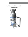
6.
Remove plastic lining from Velcro® backing
located on back of salt alarm controller.
Fig. 22
9.
Fig. 20
7.
Remove four screws securing back cover to salt
alarm controller.
Re-install back cover to salt alarm controller.
10. Using the adhesive backing on both devices place alarm controller and salt alarm sensor in a
position that will allow salt alarm controller to be
seen and heard when it is activated.
11. Insert phone cable into salt alarm sensor and salt
alarm controller.
NOTE: Salt alarm controller can be mounted up to
100 feet from salt alarm connector box using standard
phone cable from local retailers (7 foot cable is provide
with kit).
Fig. 21
8.
Install three (3) AA batteries into salt alarm
controller.
NOTE: When installing batteries - be certain to
inspect connector to ensure it is secure.
Fig. 23
12. Check for proper operation by pressing the
recessed red button on bottom of salt alarm
controller. If controller is operating properly - the
indicator light will flash and an audible tone will
be heard.
Page 11 of 16
F25405 Rev. A (0913)
WS-500 Water Softening System Installation Instructions - INSTALLATION
Fig. 24
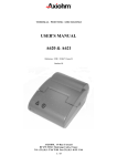
BRINE DRUM SETTINGS FOR
WS-500
NOTE: In Hobart Softeners, the brine drum mixes and
stores a solution of salt for regeneration of the softener
media. During the brine rinse cycle, this solution is
drawn from the brine drum and through the media to
regenerate it.
NOTE: The brine drum contains an adjustment to
draw the correct amount of salt (brine) solution for
each cycle. This adjustment is made in two places, the
adjuster tube and the float cup.
NOTE: The adjuster tube measures the amount of
solution that is drawn from the brine drum into the
softener during the brine rinse cycle. The float cup
height determines how much softened water flows
back into the brine drum to prepare for the next
regeneration.
NOTE: The adjuster tube is set by cutting and
removing tabs on both sides of the tube. Cut across
each tab horizontally, following the channel in the
plastic. Break off each tab individually until the proper
setting is reached. The remaining number or letter
imprinted on the tab determines the correct setting.
Fig. 25
NOTE: The float cup height determines how much
softened water flows back into the brine drum to
prepare for the next regeneration.
NOTE: The float cup is set by adjusting its height
above the bottom of the Brine Valve Assembly. By
removing the brine valve assembly and resting it on a
flat surface, the height of the float cup can be
measured with a ruler. The height is measured from
the base of the brine valve assembly to the top of the
float cup.
NOTE: Standard settings are defined by markings on
the rod of the brine valve assembly. Where the
predefined settings are not adequate, the actual float
cup height must be measured and the setting must be
measured and set according to the measured float cup
height.
F25405 Rev. A (0913)
Page 12 of 16
WS-500 Water Softening System Installation Instructions - INSTALLATION
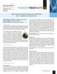
Brine Valve Settings for WS-500: 24 x 40 Brine
Valve Adjustment
Adjuster Tube
K
Float Cup
12"
NOTE: Do not drop the brine valve into the drum.
Dropping may lower the float cup, resulting in an
improper setting.
NOTE: After the adjustments have been made to the
adjuster tube and the float cup, the brine valve
assembly must be installed in the brine drum. Locate
the brine valve in the brine well so the 3/8" bent tube
is along the back of the brine well away from the brine
drum wall. The 3/8" bent tube snaps into a notch and
extends from the brine drum about 1 inch.
Fig. 26
NOTE: Determining the correct brine valve setting for
a particular application is a three step process:
1.
Determine the compensated hardness. This
requires a hardness test and an iron test on raw
water at the application site. Compensated
hardness is calculated by multiplying the ferrous
iron (in ppm) by 3 and adding it to the grains of
hardness.
2.
To test the water supply, use the water analysis
test kit available through Pro Products Inc. The
recommended kit is #2404 Deluxe Field Analysis
Kit. To order the test kit contact Pro Products at
800-285-9176 or visit www.ProProducts.com
3.
Set the adjuster tube and float cup. Use the brine
drum specifications for the WS-500 to determine
the correct settings for both the adjuster tube and
the float cup height.
Brine Valve Settings for WS-500: 24 x 40 Brine
Valve Adjustment
Salt Setting
25 lbs.
Page 13 of 16
F25405 Rev. A (0913)
WS-500 Water Softening System Installation Instructions - DISC REPLACEMENT
DISC REPLACEMENT
DISC REPLACEMENT WS-500
NOTE: The WS-500 comes with a #4 meter disc
installed at the factory. If this is not the correct disc for
a given application, locate the meter disc kit and install
the correct disc
1.
To change disc, remove screws and cap cover
from level one
Fig. 29
4.
Remove meter drive pawl.
Fig. 27
2.
Remove balance piston.
Fig. 30
5.
Remove meter disc.
Fig. 28
3.
Remove balance piston o-ring and balance
piston spring.
Fig. 31
F25405 Rev. A (0913)
Page 14 of 16
WS-500 Water Softening System Installation Instructions - DISC REPLACEMENT
6.
Install correct meter disc and reassemble in
reverse order.
NOTE: Make certain all components are correctly
installed.
NOTE: Be certain to start cap screws by hand rotating
backwards until screw drops into thread then tighten.
An alternating, crossing pattern should be used while
tightening cap screws to ensure correct cap fit. Add a
clean grade of salt at this time. Higher grades of
Pelletized Salt for impurities and solubility should be
used.
NOTE: Do not use rock salt or solar salt.
NOTE: On iron-bearing water, a salt that contains
resin cleaning additives is recommended.
7.
Open the inlet valve slowly and allow the tanks to
fill slowly with water. Water will run at the drain
until unit is full and pressurized.
8.
With the unit in service and under pressure, allow
the brine drum to fill with water until the brine
valve shuts off.
9.
After the unit is fully pressurized, purge air form
the lines by opening soft water outlet.
NOTE: When brine drum overflow could cause
damage, a ½" I.D. overflow line must be installed on
the barbed overflow fitting on drum and connected to
a drain. Make sure drain is not higher than barbed
fitting.
10. Check for plumbing leaks.
11. Check unit for proper operation.
Page 15 of 16
F25405 Rev. A (0913)
WS-500 Water Softening System Installation Instructions - DISC SELECTION
DISC SELECTION
DISC SELECTION WS-500
Using the full louver nozzle, the amount of hardness removed (in compensated gpg) will be based on the amount
of brine and the meter disc selected.
Specifications WS-500
Overdrive Operation
Alternating Operation
Salt usage / generation
25 lbs.
25 lbs.
Capacity
70,00 grains
70,00 grains
Efficiency
2,800 gr./lb.
2,800 gr./lb.
Dosing
10.0 lbs./cu. ft.
10.0 lbs./cu. ft.
Float cup setting
12"
12"
OVERDRIVE OPERATION WS-500 Disc Selection
Disc Number
1
2
3
4
5
6
7
8
Compensated Hardness *
6
12
16
20
24
30
35
40
Peak Flow During
Regeneration
28.0
28.0
28.0
20.7
15.7
12.4
10.0
8.3
* Compensated hardness in gpg = Hardness + (3 x Fe in ppm)
ALTERNATING OPERATION WS-500 Disc Selection
Disc Number
1
2
3
4
5
6
7
8
Compensated Hardness *
7
14
21
28
34
40
45
51
Gallons Between
Regeneration
8,922
4,461
2,974
2,231
1,784
1,487
1,275
1,115
20
20
20
20
15.7
12.4
10.0
8.3
Regeneration Gallons
Per Minute @ 15 psig
* Compensated hardness in gpg = Hardness + (3 x Fe in ppm)
F25405 Rev. A (0913)
Page 16 of 16