1
SERVICE MANUAL
SALAMANDER ELECTRIC
BROILER
VULCAN -
36ESB
- NOTICE This Manual is prepared for the use of trained Vulcan Service
Technicians and should not be used by those not properly
qualified.
This manual is not intended to be all encompassing. If you have
not attended a Vulcan Service School for this product, you should
read, in its entirety, the repair procedure you wish to perform to
determine if you have the necessary tools, instruments and skills
required to perform the procedure. Procedures for which you do
not have the necessary tools, instruments and skills should be
performed by a trained Vulcan Service Technician.
The reproduction, transfer, sale or other use of this Manual,
without the express written consent of Vulcan, is prohibited.
This manual has been provided to you by ITW Food Equipment
Group LLC ("ITW FEG") without charge and remains the property
of ITW FEG, and by accepting this manual you agree that you will
return it to ITW FEG promptly upon its request for such return at
any time in the future.
A product of Vulcan-Hart
3600 North Point Blvd Baltimore, MD 21222
F45545 (0315)
SALAMANDER ELECTRIC BROILER
TABLE OF CONTENTS
GENERAL . . . . . . . . . . . . . . . . . . . . . . . . . . . . . . . . . . . . . . . . . . . . . . . . . . . . . . . . . . . . . . . . . . . . . . . . . . . . . . . . . . . . . . . . . . . . . . . . . .
INTRODUCTION . . . . . . . . . . . . . . . . . . . . . . . . . . . . . . . . . . . . . . . . . . . . . . . . . . . . . . . . . . . . . . . . . . . . . . . . . . . . . . . . . . . . . . .
INSTALLATION, OPERATION AND CLEANING . . . . . . . . . . . . . . . . . . . . . . . . . . . . . . . . . . . . . . . . . . . . . . . . . . . . . . . . .
GRID POSITION AND HEAT CONTROL SETTING . . . . . . . . . . . . . . . . . . . . . . . . . . . . . . . . . . . . . . . . . . . . . . . . . . . . . .
MODELS . . . . . . . . . . . . . . . . . . . . . . . . . . . . . . . . . . . . . . . . . . . . . . . . . . . . . . . . . . . . . . . . . . . . . . . . . . . . . . . . . . . . . . . . . . . . . . .
SPECIFICATIONS . . . . . . . . . . . . . . . . . . . . . . . . . . . . . . . . . . . . . . . . . . . . . . . . . . . . . . . . . . . . . . . . . . . . . . . . . . . . . . . . . . . . . .
TOOLS . . . . . . . . . . . . . . . . . . . . . . . . . . . . . . . . . . . . . . . . . . . . . . . . . . . . . . . . . . . . . . . . . . . . . . . . . . . . . . . . . . . . . . . . . . . . . . . . .
3
3
3
3
3
3
4
REMOVAL AND REPLACEMENT OF PARTS . . . . . . . . . . . . . . . . . . . . . . . . . . . . . . . . . . . . . . . . . . . . . . . . . . . . . . . . . . . . . . .
FRONT PANEL . . . . . . . . . . . . . . . . . . . . . . . . . . . . . . . . . . . . . . . . . . . . . . . . . . . . . . . . . . . . . . . . . . . . . . . . . . . . . . . . . . . . . . . . .
LEFT SIDE PANEL . . . . . . . . . . . . . . . . . . . . . . . . . . . . . . . . . . . . . . . . . . . . . . . . . . . . . . . . . . . . . . . . . . . . . . . . . . . . . . . . . . . . .
RIGHT SIDE PANEL . . . . . . . . . . . . . . . . . . . . . . . . . . . . . . . . . . . . . . . . . . . . . . . . . . . . . . . . . . . . . . . . . . . . . . . . . . . . . . . . . . . .
INFINITE SWITCH / 3 HEAT SWITCH . . . . . . . . . . . . . . . . . . . . . . . . . . . . . . . . . . . . . . . . . . . . . . . . . . . . . . . . . . . . . . . . . . .
RACK SPRINGS . . . . . . . . . . . . . . . . . . . . . . . . . . . . . . . . . . . . . . . . . . . . . . . . . . . . . . . . . . . . . . . . . . . . . . . . . . . . . . . . . . . . . . .
HEATING ELEMENTS . . . . . . . . . . . . . . . . . . . . . . . . . . . . . . . . . . . . . . . . . . . . . . . . . . . . . . . . . . . . . . . . . . . . . . . . . . . . . . . . . .
5
5
5
6
6
7
7
SERVICE PROCEDURES AND ADJUSTMENTS . . . . . . . . . . . . . . . . . . . . . . . . . . . . . . . . . . . . . . . . . . . . . . . . . . . . . . . . . . . . 9
INFINITE SWITCH TEST (208V/240V) . . . . . . . . . . . . . . . . . . . . . . . . . . . . . . . . . . . . . . . . . . . . . . . . . . . . . . . . . . . . . . . . . . 9
3 HEAT SWITCH TEST (480V) . . . . . . . . . . . . . . . . . . . . . . . . . . . . . . . . . . . . . . . . . . . . . . . . . . . . . . . . . . . . . . . . . . . . . . . . . 9
RACK SPRING TENSION ADJUSTMENT . . . . . . . . . . . . . . . . . . . . . . . . . . . . . . . . . . . . . . . . . . . . . . . . . . . . . . . . . . . . . . . 9
HEATING ELEMENTS TEST . . . . . . . . . . . . . . . . . . . . . . . . . . . . . . . . . . . . . . . . . . . . . . . . . . . . . . . . . . . . . . . . . . . . . . . . . . 10
ELECTRICAL OPERATION . . . . . . . . . . . . . . . . . . . . . . . . . . . . . . . . . . . . . . . . . . . . . . . . . . . . . . . . . . . . . . . . . . . . . . . . . . . . . . . .
COMPONENT FUNCTION . . . . . . . . . . . . . . . . . . . . . . . . . . . . . . . . . . . . . . . . . . . . . . . . . . . . . . . . . . . . . . . . . . . . . . . . . . . .
SEQUENCE OF OPERATION . . . . . . . . . . . . . . . . . . . . . . . . . . . . . . . . . . . . . . . . . . . . . . . . . . . . . . . . . . . . . . . . . . . . . . . . .
208/240V - WIRING DIAGRAM . . . . . . . . . . . . . . . . . . . . . . . . . . . . . . . . . . . . . . . . . . . . . . . . . . . . . . . . . . . . . . . . . . . . . . . .
480V - WIRING DIAGRAM . . . . . . . . . . . . . . . . . . . . . . . . . . . . . . . . . . . . . . . . . . . . . . . . . . . . . . . . . . . . . . . . . . . . . . . . . . . . .
11
11
11
12
13
TROUBLESHOOTING . . . . . . . . . . . . . . . . . . . . . . . . . . . . . . . . . . . . . . . . . . . . . . . . . . . . . . . . . . . . . . . . . . . . . . . . . . . . . . . . . . . . . 14
TROUBLESHOOTING . . . . . . . . . . . . . . . . . . . . . . . . . . . . . . . . . . . . . . . . . . . . . . . . . . . . . . . . . . . . . . . . . . . . . . . . . . . . . . . . . 14
© VULCAN 2015
F45545 (0315)
Page 2 of 14
SALAMANDER ELECTRIC BROILER - GENERAL
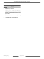
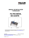
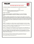
GENERAL
NOTE: Using accessory options, Salamander
broilers can be mounted to the wall, over a range or
placed onto an appropriate table top by using 4" legs.
INTRODUCTION
This manual is for the Vulcan and Wolf Electric
Salamander Broilers. Procedures in this manual will
apply to all models unless specified. Pictures and
illustrations will be of model 36ESB unless otherwise
noted.
GRID POSITION AND HEAT
CONTROL SETTING
For detailed information refer to OPERATING THE
BROILER and GRID ADJUSTMENT in the Installation
& Operation Manual.
All of the information, illustrations and specifications
contained in this manual are based on the latest
product information available at the time of printing.
MODELS
INSTALLATION, OPERATION AND
CLEANING
Vulcan
•
36ESB-208
For detailed installation, operation and cleaning
instructions, refer to Installation & Operation Manual
sent with each unit. The manual is also available
online at www.vulcanequipment.com.
•
36ESB-240
•
36ESB-480
SPECIFICATIONS
3 PHASE MACHINE INFORMATION
NOMINAL AMPS PER LINE WIRE
Model
Total KW
208V
240V
480V
X
Y
Z
X
Y
Z
X
Y
Z
OHMS per
Element
36ESB-208
4.5
11.0
18.9
11.0
—
—
—
—
—
—
19.2
36ESB-240
4.5
—
—
—
9.4
16.4
9.4
—
—
—
25.6
36ESB-480
4.5
—
—
—
—
—
—
4.9
8.4
4.9
102.4
NOTES:
1.
Values in the table are nominal. Tolerance is +5/-10%.
2.
Voltage values are @ 60Hz.
3.
Resistance values (ohms) are @ 77° F.
4.
2.25KW per element assembly (left or right).
1 PHASE MACHINE INFORMATION
Model
Total KW
NOMINAL AMPS PER LINE WIRE
208V
240V
OHMS per Element
36ESB-208
4.5
21.6
—
19.2
36ESB-240
4.5
—
18.8
25.6
NOTES:
1.
Values in the table are nominal. Tolerance is +5/-10%.
2.
Voltage values are @ 60Hz.
3.
Resistance values (ohms) are @ 77° F.
4.
2.25KW per element assembly (left or right).
Page 3 of 14
F45545 (0315)
SALAMANDER ELECTRIC BROILER - GENERAL
TOOLS
Standard
•
Standard set of hand tools
•
VOM with ability to measure micro amp current.
VOM with minimum of NFPA-70E CAT III 600V,
UL/CSA/TUV listed. Sensitivity of at least 20,000
ohms per volt. Meter leads must also be rated at
CAT III 600V.
•
Clamp on type amp meter for measuring heating
element current draw.
•
Temperature tester (thermocouple type)
F45545 (0315)
Page 4 of 14
SALAMANDER ELECTRIC BROILER - REMOVAL AND REPLACEMENT OF PARTS
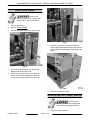
REMOVAL AND REPLACEMENT OF PARTS
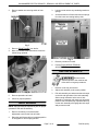
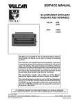
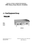
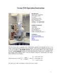
FRONT PANEL
Disconnect the
electrical power to the machine and
follow lockout / tagout procedures.
1.
Remove screws that secure front panel to broiler.
2.
Remove INFINITE SWITCH / 3 HEAT SWITCH
from front panel.
3.
Reverse procedure to install.
Fig. 2
4.
Remove screws securing left side panel. Slide
panel toward the front of broiler until panel clears
front mounting area then remove the panel.
Fig. 1
LEFT SIDE PANEL
Disconnect the
electrical power to the machine and
follow lockout / tagout procedures.
1.
Remove crumb tray.
2.
Remove FRONT PANEL.
3.
Position the rack assembly to access panel
screws in the broiler opening area.
Fig. 3
5.
Page 5 of 14
Reverse procedure to install.
F45545 (0315)
SALAMANDER ELECTRIC BROILER - REMOVAL AND REPLACEMENT OF PARTS
RIGHT SIDE PANEL
Disconnect the
electrical power to the machine and
follow lockout / tagout procedures.
1.
Remove crumb tray.
2.
Remove FRONT PANEL.
3.
Remove screws securing plate stop to broiler.
Fig. 5
6.
Remove screws securing right side panel to
broiler. Slide panel toward the front of broiler until
panel clears front mounting area then remove the
panel.
Fig. 4
4.
Pull knob off the handle on rack positioning
bracket then remove plate stop.
5.
Position the rack assembly to access panel
screws in the broiler opening area. Remove
screws from this area and the front of panel.
Fig. 6
7.
Reverse procedure to install.
INFINITE SWITCH / 3 HEAT SWITCH
Disconnect the
electrical power to the machine and
follow lockout / tagout procedures.
1.
F45545 (0315)
Page 6 of 14
Remove knob from switch.
SALAMANDER ELECTRIC BROILER - REMOVAL AND REPLACEMENT OF PARTS
2.
Remove washer nut securing switch to front
panel.
3.
Loosen nuts to remove any remaining tension on
springs.
4.
Access the bottom of broiler and remove springs
from the lower arm casting and eye bolt.
Fig. 7
3.
Remove FRONT PANEL from broiler.
4.
Note wire locations then disconnect wires from
switch being replaced.
Fig. 9
5.
Reverse procedure to install.
6.
Perform RACK SPRING TENSION
ADJUSTMENT.
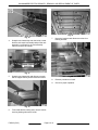
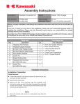
HEATING ELEMENTS
Disconnect the
electrical power to the machine and
follow lockout / tagout procedures.
1.
Remove crumb tray from broiler.
2.
Adjust rack assembly to the center position.
3.
Pull rack assembly out and access the rack stops
on the left and right sides of the rack assembly.
Allow enough clearance at the rear of rack
assembly to rotate the rack stops to a horizontal
position. If the rack assembly is pulled all the way
out the rack assembly will engage the rack stops
and prevent removal.
Page 7 of 14
F45545 (0315)
Fig. 8
5.
Reverse procedure to install.
6.
Check for proper operation.
RACK SPRINGS
NOTE: Springs should be replaced in pairs for proper
operation of the rack lift assembly.
1.
Remove crumb tray to access tension
adjustment nuts from the front of broiler.
2.
Raise the rack lift assembly to its highest position
on stop plate to relieve spring tension.
SALAMANDER ELECTRIC BROILER - REMOVAL AND REPLACEMENT OF PARTS
Fig. 13
Fig. 10
4.
7.
Grasp the rack assembly near the broiler, rotate
both the rack stops horizontally and pull the rack
assembly out enough for the rack assembly
frame to clear the rack stops.
Note wire locations and disconnect wires from
heating element.
Fig. 11
5.
Grasp the rack assembly and drip tray on each
side to support the tray and remove from broiler.
Fig. 14
8.
Reverse procedure to install.
9.
Check for proper operation.
Fig. 12
6.
From inside broiler cooking area, remove screws
securing heating element to broiler.
F45545 (0315)
Page 8 of 14
SALAMANDER ELECTRIC BROILER - SERVICE PROCEDURES AND ADJUSTMENTS
SERVICE PROCEDURES AND ADJUSTMENTS
Certain procedures in this section require electrical test or measurements while
power is applied to the machine. Exercise extreme caution at all times and follow Arc Flash
procedures. If test points are not easily accessible, disconnect power and follow Lockout/Tagout
procedures, attach test equipment and reapply power to test.
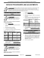
INFINITE SWITCH TEST (208V/
240V)
1.
Remove FRONT PANEL.
2.
Reconnect power to machine.
3.
Check input voltage at L3 and L2 on the switch
terminals.
Disconnect the
electrical power to the machine and
follow lockout / tagout procedures.
4.
Check for the correct output voltage at the output
terminals for all knob settings of the switch.
NOTE: Refer to AI3829 in WIRING DIAGRAMS for
switch terminal locations.
1.
Remove FRONT PANEL.
2.
Connect a voltmeter to the output terminals H1
and H2.
3.
Reconnect power to machine.
4.
Turn knob to the desired setting.
5.
Compare the percentage of ON time to OFF time.
L3 Input -
L2 Input -
Knob Settings
Output at
Terminal(s)
Output at
Terminal(s)
High
1&3
2
Med
1
2
Low
1
3
5.
RACK SPRING TENSION
ADJUSTMENT
NOTE: ±7.5% tolerance allowable.
Knob
Setting
% on Time
Seconds
on
Seconds
off
Hi
100
ALL
0
Med.
48
15
15
Low
37
8
14
Med. Low
28
7
24
Very Low
7
3
33
6.
If the voltages are not correct, replace the switch
as outlined under INFINITE SWITCH / 3 HEAT
SWITCH.
1.
Access the springs on the bottom of broiler.
2.
Tighten nut to adjust rack spring tension. Adjust
both springs equally so there is approximately
3/4" of thread above the nut. If additional rack
spring tension is required, tighten each nut an
additional 2-3 turns.
3.
Check for proper operation.
If the percentage is not correct, replace the
switch as outlined under INFINITE SWITCH / 3
HEAT SWITCH.
3 HEAT SWITCH TEST (480V)
Disconnect the
electrical power to the machine and
follow lockout / tagout procedures.
NOTE: Refer to AI3830 in WIRING DIAGRAMS for
switch terminal locations.
Page 9 of 14
F45545 (0315)
SALAMANDER ELECTRIC BROILER - SERVICE PROCEDURES AND ADJUSTMENTS
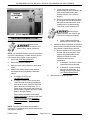
1)
If both measured values are
approximately the same as listed in the
machine information table, then
heating elements are functioning
properly.
2)
If one or both of the measured values
do not agree with the values listed in
the machine information table, then
heating element is malfunctioning.
Turn broiler control switches OFF.
Disconnect the
electrical power to the machine and
follow lockout / tagout procedures.
Fig. 15
HEATING ELEMENTS TEST
a.
C.
Disconnect the
electrical power to the machine and
follow lockout / tagout procedures.
Install a replacement heating
element then proceed to step 2.
If unable to check current draw, a resistance
check (ohms) at heating element terminals
may indicate a malfunctioning element.
1)
1.
Access the HEATING ELEMENTS.
Remove lead wires from the heating
element and check resistance. See
machine information tables under
SPECIFICATIONS for proper
resistance values at room
temperature.
2.
Reconnect power to machine.
a.
3.
Set broiler heat control switches to the highest
setting.
If resistance is incorrect, install a
replacement heating element.
b.
If resistance is correct, heating
element has tested okay. If
heating element is still suspect,
see TROUBLESHOOTING.
NOTE: On 208V/240V broilers, the two heat controls
are Infinite load switches; On 480V broilers, the two
heat controls are 4 Position 3 Heat switches.
4.
Measure the voltage at the heating element
terminals and verify it against the data plate
voltage.
5.
A.
If voltage is incorrect, see
TROUBLESHOOTING.
B.
If voltage is correct, check current draw
(amps) through the heating element lead
wires at the X and Z phases on the outlet
side of the broiler terminal block. The X
phase value is the current draw for the left
element and the Z phase value is the current
draw for the right element.
See machine information tables under
SPECIFICATIONS for proper current draw
values and the appropriate 208/240V WIRING DIAGRAM or 480V - WIRING
DIAGRAM for heating element phase
connections.
NOTE: Checking current draw is the preferred
method over a resistance check when a clamp on type
amp meter is available.
F45545 (0315)
Page 10 of 14
Check broiler for proper operation.
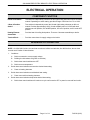
SALAMANDER ELECTRIC BROILER - ELECTRICAL OPERATION
ELECTRICAL OPERATION
COMPONENT FUNCTION
Infinite Load Switch . . .
Two switches independently control the left and right heating elements on 208V and 240V
models. Depending on switch setting, provides a range of ON time from 7% to 100%.
3 Heat, 4 Position
Switch . . . . . . . . . . . . . . .
Two switches independently control the left and right heating elements on 480 volt
models. Provides approximately 100% of total available power of 4.5 KW with both
switches set to HI position, 50% at MED position, 25% at LO position, and 0% at the OFF
position.
Heating Element
Assemblies . . . . . . . . . .
Provides heat for broiling food product. There are 2 element assemblies per broiler.
Terminal Block . . . . . . .
Provides connections for supply voltage to the broiler.
SEQUENCE OF OPERATION
NOTE: On 208V/240V broilers, the two heat controls are Infinite load switches; On 480V broilers, the two heat
controls are 4 Position 3 Heat switches.
1.
2.
Conditions
A.
Broiler connected to correct supply voltage.
B.
Building circuit breakers ON (power to machine).
C.
Broiler heat control switches are OFF.
D.
Broiler at room temperature.
Broiler heat control switches are turned to desired heat setting.
A.
3.
Broiler heat control switches reach desired heat setting.
A.
4.
Power to heating elements.
Power removed from heating elements.
Broiler heat control switches drop below desired heat setting.
A.
Broiler heat control switches will continue to cycle until turned to OFF or power is removed from broiler.
Page 11 of 14
F45545 (0315)
SALAMANDER ELECTRIC BROILER - ELECTRICAL OPERATION
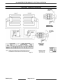
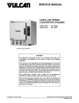
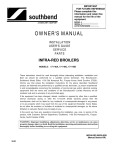
208/240V - WIRING DIAGRAM
Fig. 16
F45545 (0315)
Page 12 of 14
SALAMANDER ELECTRIC BROILER - ELECTRICAL OPERATION
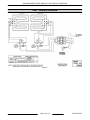
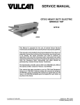
480V - WIRING DIAGRAM
Fig. 17
Page 13 of 14
F45545 (0315)
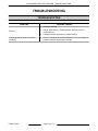
SALAMANDER ELECTRIC BROILER - TROUBLESHOOTING
TROUBLESHOOTING
TROUBLESHOOTING
SYMPTOM
No heat.
Cooking problems (product not done/
overdone).
F45545 (0315)
POSSIBLE CAUSES
1.
No power to broiler.
2.
Infinite (208V/240V) or 3 heat switches (480V) are OFF or
malfunctioning.
3.
Heating elements inoperative or malfunctioning.
1.
Refer to Installation & Operation Manual for recommended grid
position and heat control switch settings .
Page 14 of 14