1
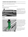
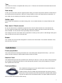
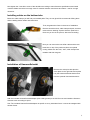
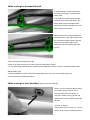
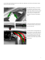
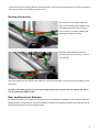
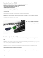
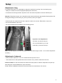
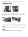
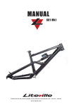
MANUAL 301 Mk8
Please look for the newest updates of this manual at www.liteville.com > service > manual
and at liteville.com
Limits for the Liteville 301 Frame
Please be aware, not all parts available on the market can be used on the Liteville 301 frame and some parts
simply should not be used! The following parts have limits:
Fork
Only forks with a maximum built height of 565 mm are permitted for use.
Crank/Bottom Bracket
Not all available crank/bottom bracket
units can be used. The bottom bracket
shell width is 73mm.
Look for clearance
Make sure the left crank does not collide
with the left chain stay. Since the Liteville
301 frame is only suitable for Shimano EType front derailleurs you need a bottom
bracket that can be used with one.
Seatpost
The Liteville 301 frame needs a seatpost with a diameter of 34.9 mm.
To prevent frame damage, the seatpost
needs to be inserted down to the mark on
the seat tube. Frames with Works Finish
do not have a laser etching. Nevertheless, you need to adhere to the minimum
inserting depth (120 / 140mm, see picture
on left). Note that the minimum insertion
depth is dependent on length of the
seatpost length above the seat tube
(below or above 200mm).
Simply stated: if the seat post is pulled
out more than 200mm (upper edge of
seat tube to seat rails) only the lower
laser etching is valid!
2
Tires
The Liteville 301 frame is compatible with tires up to 2.5“. Frames size S and XS have limited clearance due
to shorter chain stays.
Seat clamp
In case you do not want to use the original Syntace clamp you need a clamp with a diameter of 38mm due to
the oversize build of the seat tube. Watch for enough clearance of the rear triangle during compression. To
test, deflate shock completely and carefully compress the rear entirely.
Shifter cable
For a trouble-free installation use cable housing with a 4 mm outside diameter, for example Shimano SISSP41.
Rear shock / Shock mounts
Do not use shocks with an installation length other than 190 mm. Shock stroke can not exceed 50 mm.
Tip: The Liteville 301 frame has a special low-ratio suspension design and does not work well with every
shock available. Our shocks have been specifically tuned for our frames.
Hint: A slight brush of the rear wheel at full compression is nothing to worry about. It will damage nothing and
may only leave a brush mark on the seat tube.
Brakes
The Liteville 301 frame has been designed for exclusive use of disc brakes. The maximum diameter of the
rear disc rotor is 210 mm.
Installation
Frame preparation
The contact surfaces for bearings and brakes etc. have already been prepped at the factory – you do not
need to surface anything to install headset, bottom bracket or brakes.
Headset / fork
The headset bearings have been pressed into the frame by the factory. In case you need to change bearings,
do not forget to use grease and make sure the bearings are pressed in evenly and completely. It is best to
use a special tool for the task.
Fork installation
First, install both seals (grey lip on the outside, black o-ring on the inside) on
the cover of the SuperSpin headset.
Install the larger of the two slotted rings (the base plate, see picture) onto the
steerer tube. Insert the steerer tube into the head tube, add the smaller slotted
ring onto the steerer tube and install the black cover plate. Make sure the fork
does not collide with the frame when turning.
3
Now slide the lower (depending on fork, either the tapered or the 1 1/8” one) of the two slotted bearing cones
onto the steerer tube. If using a 1 1/8” fork you now need to install the lower 1 1/8” reducer in the lower bearing (do not forget to grease).
Insert fork into the frame, slide upper 1 1/8” cone onto steerer tube and install the cover plate.
SuperSpin tapered, lower
1.5, upper 1 1/8
SuperSpin 1 1/8 with reducer
for 11/8 steerer tubes
Tip 1: Before installing the cover plate, grease bearing heavily. It will keep moisture away and aids easy
spinning.
Tip 2: Pull the headset tight with the adjustment bolt, then loosen the bolt again. Only now adjust bearing
play. With that procedure you can make sure that the bearings have been seated correctly and will spin
easily.
Make sure the fork does not hit the down tube when spinning the bar.
Bar / Stem
Install bar and stem according to manufacturer’s instructions onto the steerer tube.
Hint: test ride first with uncut steerer tube. You would not be the first person to be ticked off because you cut
the steerer tube too short!
Shift levers
Install levers according to manufacturer’s specifications.
Bottom bracket / crank & front derailleur
Liberally grease contact surfaces for the bottom bracket. Fix the E-Type derailleur with the bolt (supplied by
Shimano).
Important: Do not use a spacer between BB and derailleur.
Now install both BB bearing cups according to installation instructions. Use enough grease! From experience we know that especially outboard bearings tend to creak if not enough grease has been applied to the
contact surfaces.
4
Now tighten the 5 mm Allen screw of the derailleur according to manufacturers specifications and install
crankset. Make sure there is enough room for rotation between crank arms and frame – test for enough
clearance.
Installing cables on the bottom tube
Below the cable clamps you will find pre-installed pads. They are not glued! We recommend affixing them
while installing shifter cables and brake lines.
To do, degrease the frame in the area of installation.
Remove aluminium bolt, cable clamp and pad, and then
remove brown backing of pads. Stick the pads to the
frame as you see in the picture, above the threading.
Now you can mount the rear shifter cable and the rear
brake line on top of the pads to achieve an optimal
routing. Make sure the front, “half”, cable clamps face
inwards with their tongues.
Installation of HammerSchmidt
Remove the main-pivot bolt plus the
cover plate on the right side and replace
it by the HammerSchmidt titanium bolt
from the optional HammerSchmidt kit.
Add the included HammerSchmidt adapter (with a little grease) to the ISCG mount and install the HammerSchmidt crank according to specs.
Hint: The included HammerSchmidt adapter is specific to every individual frame. It cannot be swapped with
another frame.
5
Cable routing for HammerSchmidt
To install cabling for HammerSchmidt,
you need to exchange 3 clamps on the
bottom tube.
First, replace the single clamp through
a double clamp from further down. The
shifter cable for the HammerSchmidt
crank will be routed in parallel to the rear
shifter cable on the outside.
Replace the two first clamps installed to
the bottom tube by the triple clamps from
the HammerSchmidt kit. Behind the last
triple clamp the shifter cable will go
directly into the HammerSchmidt crank
housing.
Cable routing with installed bottle cage
• Either route cable in the area of bottle cage with small plastic clamps.
•O
r use shrink tube (preferably thick walled stuff like Hellermann Tyton) to route in parallel to shifter cable
Without bottle cage
• Install an additional Liteville “HammerSchmidt cable clamp” onto the second bottle cage inser
•U
se shrink tubing as described above
Cable routing for front derailleur (without HammerSchmidt)
Before you can install the cable housing,
you need to unbolt the front shock
mount and fold down the shock. To
mount the cable housing, you will find
special mounts on the bottom side of the
top tube.
Proceed as follows:
Sharply bend a zip tie about 10 – 15 mm
behind the tip so get something close to
6
a hook. Now insert the hooked zip tie into the cable mount. Make sure you insert only far enough so the tip
snaps over the little cross ridge.
By pulling and pushing, you can direct
the zip tie all the way through until the
head is at the top tube. Now you can install the cable housing (and the optional
cable housing for an adjustable seat
post. Note: only pull the zip tie tight by
hand!
Cut the zip tie right at the head and turn
the heads all the way to the top tube so
they do not stick out.
The shifter cable is running between top
tube and shock. Let the shifter cable run
through left rear shock mount and seat
tube. The shifter housing for the E-type
derailleur should neither run in a large
arch nor in a very “direct” way to ensure
good function.
7
Cable routing for the rear derailleur
The shifter cable for the rear derailleur is
being routed directly through the seat
tube into the chain stay. To protect the
cable even better from corrosion, we use
an additional, flexible tube.
Hint: Do not remove the transparent plastic tube. In case you did remove it, reinstall it by pushing it thoroughly into its seat (blue in the picture) and do NOT use lubrication.
The exit for the shifter cable is at the
lower end of the right chain stay.
Changing a shifter cable housing
• Leave the transparent tube in place
•C
ut the new cable housing in a skewed fashion
• Spray a little silicone spray into the guide
tube
• Insert shifter cable from the front until it
is at the chain stay yoke
• Use the rest of the cable housing as a
handle by rolling it up. Let the housing
find its way by turning and pushing at the
same time. It will work even easier if the
rear triangle will be moved up and down
by about 1 – 2cm (remove shock mount).
8
•P
ush further until the housing hits the Horst link and let it find its way though the hole by turning and pushing
•N
ow cut the ends of the housing as usual. Done!
Routing of brake line
The brake lines and shifter cables are
being routed continuously. Please to not
over-tighten the bolts of the clamps to
avoid crimping. If crimped, shifting and
braking lines will lose function.
Be aware that the brake line will be
shortened during compression. Leave it
long enough!
Use the included clips for mounting the brake line on the left chain stay. If you use zip ties, squeaking noises
may occur.
Be aware: The routing pictured is for brake callipers where you can turn the line towards the rear. It
will vary with other brake models.
Rear derailleurs from Shimano:
All derailleurs starting from model year 2009 will work (only Shadow!). Installation of old derailleurs (with the
large diameter housing bend) is not recommended on Liteville 301 frames from Mk8 on because they do not
harmonize well with the new, low-profile routing.
9
Rear derailleurs from SRAM:
SRAM X.7, X.9 and X.0 will fit - as well as all older SRAM rear derailleurs.
Reasons for preference of newer Shimano and SRAM derailleurs:
•D
irect cable routing without unnecessary arcs
•B
etter protection against branches
•R
educed friction by avoiding large radii
•N
o crashing of derailleur against chain stay
•R
educed noise
Install and adjust the derailleur according to the manufacturer’s specifications.
Attention: For perfect protection, install the optional Syntace RockGuard II. There are different models for
SRAM, Shimano Shadow and Saint models.
Tip: There is a sticker included for the
front derailleur. Install it as pictured to
reduce chain slap at the front derailleur.
Saddle, seat post and seat tube
Check the seat tube for edges and burrs. Remove them with fine sanding paper before inserting the seat
post.
Attention: If fully inserted, the seat post may reach the “dent” for the E-type front derailleur. If you try to force
it any deeper, you may damage seat post and/or frame.
Attention: Observe the “minimum insert” mark at the seat tube as described in the chapter about limits.
Install saddle according to manufacturers specifications.
Tip: Cut the seat post to the “minimum insert” dimension after being sure that it works well. That way you can
lower the seat post to the max.
10
Setup
Adjustment of sag
For optimal performance, it is advisable to adjust the Liteville 301 precisely. Do it the following way:
• • Ride your Liteville 301 with full equipment (backpack, helmet etc.)
•L
ook down onto the sag indicator “Dynamic Level” and check the position of the two indicator pins..
Attention: Especially at night, one is tempted to reach down and feel the sag instead of looking down. We
strongly discourage you from doing so; you may severely crush your fingers!
• If the two pins do not point at each other, adjust air volume in the shock. Either add or remove air.
•O
ur recommendation is pin-to-pin.
• You can see adjustment possibilities in the following picture.
Dynamic Level adjustments:
Soft: Max. pin above frame pin
Our recommendation: pin-to-pin
Hard: Max. pin below frame pin
Note: A small backpack may raise the weight on the rear axle enough to make an air volume adjustment
necessary.
Adjustment of rebound:
•R
ide at medium speed off a curb. The chassis should only bounce once.
• If the rebound is too fast (chassis bounces more than once), close the rebound circuit a bit.
Please be aware: the rear end should not rebound too slowly either or else the suspension will “pack up”
after riding over several obstacles in quick succession.
Please observe installation instructions and manual from the manufacturer of the shock.
11
Build-in interfaces
Adjustable seatpost with remote
The Liteville 301 Mk8 is ready for installation of an adjustable seatpost with remote actuation. Optimum function is only guaranteed for posts where the cable is mounted at the seat clamp area and not at the head. Use
only cable housing with an diameter of 4mm (for example Shimano SIS-SP41).
Syntace SCS Chain Guide
Integrated connections for the patented Syntace SCS chain guide are standard at the Liteville 301 Mk8.
The future Syntace SCS chain guide offers low weight and an unknown precision coupled with reliability for
single, double and triple cranks.
Maintenance and care
Bearings
All bearings used are greased for life and do not need to be disassembled to be repacked with grease. In
case of a defective bearing you can order a new bearing from your dealer or from Liteville.
Headset
In case you need to change the headset you can order a new one through your dealer or from
directly Liteville.
12
Bolts
All frame bolts used are high-tensile strength titanium bolts. They have been manufactured especially for our
Liteville frames. In case of loss or damage you can order them through your dealer or from Liteville.
On all frame bolts a thread lock has been applied, so make sure you heat them with a hot air gun if you want
to disassemble them. Use a thread lock (like Syntace Bond 48) when reinstalling!
From time to time make sure all bolts are still tightened– torque values can be found laser-etched onto the
frame on black anodized frames. You will also find torque values in the rear of this manual.
Hint: Sometimes one needs to do the opposite of what one expects…for example, if it creaks up front, grease in the rear. The suspected creaking from the bottom bracket might not be caused there at all. Leave the
BB alone and try this first:
•R
emove cassette
•A
pply copper paste thoroughly to rotor surface
•A
fter re-installing cassette tighten with full torque
Surface
Never use a high-pressure washer to clean your frame! The high water pressure will force water into the
bearings and premature corrosion and wear will follow. Dirt, blown away by high water pressure, will scratch
the surface and mar it permanently.
To clean your frame, first use water from a hose and then a soft sponge with warm water, preferably with a
few drops of dishwashing detergent. Dry frame with a soft cloth. To achieve a nice sheen, use silicone spray
and wipe with a soft cloth.
Important: make sure the silicone spray does not reach your brakes or rotors. Almost complete loss of
braking power will be the result if silicon contaminates brakes. In case brakes are contaminated, clean rotors
with brake cleaner and install new brake pads!
In addition to the available surfaces race black anodized and your custom color in powder coat, we offer in
every production run a limited edition of Works Finish frames. The new Liteville Works Finish is a genuine raw
aluminium surface, no imitation. You can see the irregular marks of the manual work.
Changes of surface color and stains are standard with this finish. Over time it develops the charm of natural
patina on the Works Finish frame. The surface can be re-worked anytime with Scotch-Brite or can be coated.
You will find two Scotch-Brite pads included with every Works Finish frame. Please try their effectiveness in
an area not immediately visible to make sure you will like it.
Logos on Works Finish:
You will find two logos cut from 3M material with the frame. If you
stick them onto the frame analoguous to the anodized frame or in
a different fashion – it is yours to decide!
13
Maximum torque:
15 Nm
10 Nm
1 Nm
10 Nm
110-20 Nm
without
thread lock
Tight bolts only
very smooth
15 Nm
6 Nm
6 Nm
blue: medium duty thread lock
6 Nm
10 Nm
6 Nm
10 Nm
Travel identification:
You can see the lever travel also on the basis of the
„Dynamic Level“ Sag-Indicators position:
120 mm Lever
140 mm Lever
160 mm Lever
14
green: heavy duty thread lock
Notes:
15
Syntace GmbH Am Mühlbach 5C D - 87487 Wiggensbach
Tel. +49 (0)8370 929988 Fax +49 (0)8370 929888
[email protected]
Sales for Germany, Austria and Switzerland:
Syntace GmbH Dammweg 1 D - 83342 Tacherting
Tel. +49 (0)8634 66666 Fax +49 (0)8634 6365
Current: 20.09.2010
16
[email protected]