1
OC230 --1.qxp
8/28/00 1:54 PM
Page 1
2000
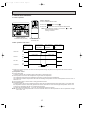
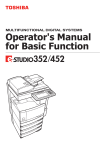
SPLIT-TYPE, AIR CONDITIONERS
No.OC230
TECHNICAL & SERVICE MANUAL
Series PK
Wall Mounted
Indoor unit
[Model names]
[Service Ref.]
PK-1.6GKL
PK-2GKL
PK-1.6GKL
PK-2GKL
This manual does not cover
the following outdoor units.
When servicing them, please
refer to the service manual
No.OC127 Revised Edition-A
and this manual in a set.
[Service Ref.]
PU-1.6VLJA2
PU-2VJA2
CONTENTS
Indoor unit
ON/OFF
Remote controller
1. PART NAMES AND FUNCTIONS ·······················2
2. SPECIFICATIONS ················································4
3. DATA·····································································6
4. OUTLINES AND DIMENSIONS ·························10
5. WIRING DIAGRAM ············································11
6. REFRIGERANT SYSTEM DIAGRAM······················12
7. OPERATION FLOW-CHART ··································13
8. MICROPROCESSOR CONTROL ···························16
9. TROUBLESHOOTING ···········································29
10. SYSTEM CONTROL ··········································35
11. DISASSEMBLY PROCEDURE···························40
12. PARTS LIST ·······················································44
13. OPTIONAL PARTS·············································46
OC230 --1.qxp
1
8/28/00 1:55 PM
Page 2
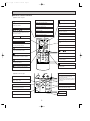
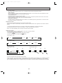
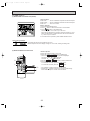
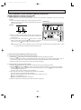
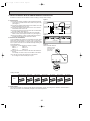
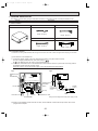
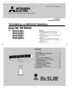
PART NAMES AND FUNCTIONS
● Indoor Unit
Filter
Air intake grille
Air intake
Auto vane
Guide vane
Air outlet
2
OC230 --1.qxp
8/28/00 1:55 PM
Page 3
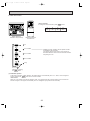
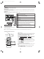
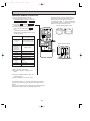
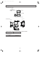
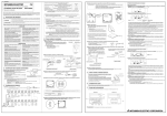
●Wireless remote controller
● When cover is open.
ADDRESS display
display
display
Displays the refrigerant address.
Lights up while transmission to the indoor unit
is mode using switches.
UNIT NO. display
SET TEMP. display indicates desired temperature set.
Displays the number of unit..
display
OPERATION MODE display
Operation mode display indicates which operation mode is in effect.
FUNCTION NO. display
Displays the mode.
DIsplays the current time.
SELECTION NO. display
“
Displays the selection number..
• FUNCTION display
TEST RUN
•
CHECK
”display
Flashes when the current time is displayed.
Lights up when function are set..
•
CLOCK display
TIMER display
display
ADDRESS
UNIT No.
FUNCTION No.
˚C
SELECTION No.
CHECK&TEST RUN display indicates that the
unit is being checked or test-run.
Displays when in timer operation or when setting timer.
AM
➡
”“
➡
“
PM
FUNCTION
” display
AM
TEST RUN
display
PM
CHECK
Displays the order of timer operation.
ON/OFF
Displays when batteries are dead.
“
START
display
MODE
The vertical direction of airflow is indicated.
FAN
STOP
VANE
HR.
display
FAN SPEED display indicates which fan
speed has been selected.
MIN.
”“
” display
Displays whether timer is on or off.
“
▼
”“
▼
TEMP.
” display
Displays when the current time and the timer
time can be changed.
RESET
TEMP. button
display
SET TEMPERATURE button sets any desired
room temperature.
The unit is turned ON and OFF alternately
each time the button is pressed.
TEMP.
● When cover is open.
ON/OFF
MODE SELECT button
Used to switch the operation mode between
cooling , drying , mode.
START
MODE
FAN SPEED SELECT button
FAN
STOP
VANE
HR.
TIMER CONTROL buttons
STOP (OFF timer): when this switch is set,
the air conditioner will be automatically
stopped at the preset time.
START (ON timer): when this switch is set, the
air conditioner will be automatically started at
the preset time.
HR. and MIN.buttons
Buttons used to set the “hour and minute” of
the current time and timer settings.
Used to change the fan speed.
MIN.
RESET
button
VANE CONTROL button
RESET button
Used to change the airflow direction.
3
OC230 --1.qxp
2
8/28/00 1:55 PM
Page 4
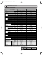
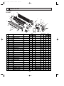
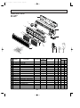
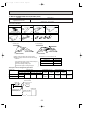
SPECIFICATIONS
1. STANDARD SPECIFICATION
Service Ref.
Item
Indoor, Outdoor D.B. / W.B.°C
Condition
Capacity w1
Btu/h
W
kW
REFRIGERANT PIPING
OUTDOOR UNIT
INDOOR UNIT
Total input w1
Service Ref.
Power supply(phase, cycle,voltage)
kW
Input
A (%)
Running current (Power factor)
A
Starting current
External finish
Heat exchanger
Fan
Fan(drive) o No.
kW
Fan motor output
m3/min (CFM)
Airflow (Low-High)
Pa (mmAq)
External static pressure
kW
Booster heater
Operation control & Thermostat
dB
Noise level (Low-High) w2
mm (in.)
Cond. drain conn. I.D.
W
mm (in.)
D
mm (in.)
Dimensions
H
mm (in.)
kg (lbs)
Weight
Service Ref.
Power supply (phase, cycle, voltage)
kW
Input
A (%)
Running current /Power factor
A
Starting current
External finish
Refrigerant control
Compressor
Model
kW
Motor output
Starter type
Protection devices
Heat exchanger
Fan
Fan(drive) o No.
kW
Fan motor output
m3/min(CFM)
Airflow
Defrost method
dB
Noise level w2
mm (in.)
W
mm (in.)
Dimensions
D
mm (in.)
H
kg (lbs)
Weight
W
Crankcase heater
kg (lbs)
Refrigerant Charge
mm (in.)
Liquid
Pipe size O.D.
mm (in.)
Gas
Indoor side
Connection method
Outdoor side
Between the indoor &
Height difference
outdoor units
Piping length
PK-1.6GKL
PK-2GKL
27/19.0°C, 35/24°C
27/19.0°C, 35/24°C
Cooling (JIS B8616,GB4706.32-96)
Cooling (JIS B8616,GB4706.32-96)
19,100
13,300
5,600
3,900
2.51/2.55
1.49/1.59
PK-2GKL
PK-1.6GKL
Single, 50Hz, 220/240V
Single, 50Hz, 220/240V
0.07
0.07
0.33(96/88)
0.33(96/88)
0.4
0.4
Munsell 0.70Y 8.59/0.97
Munsell 0.70Y 8.59/0.97
Plate fin coil
Plate fin coil
Line flow (direct) o 1
Line flow (direct) o 1
0.030
0.030
9-12 (318-424)
9-12 (318-424)
0 (direct blow)
0 (direct blow)
—
—
Wireless remote controller & Built-in
Wireless remote controller & Built-in
36 - 43
36 - 43
20 (13/16)
20 (13/16)
990 (39)
990 (39)
235 (9-1/4)
235 (9-1/4)
340 (13-3/8)
340 (13-3/8)
16 (35)
16 (35)
PU-1.6VLJA2
PU-2VJA2
Single, 50Hz, 220/240V
Single, 50Hz, 220/240V
1.42 / 1.52
2.44 / 2.48
6.7 / 6.9 (97/92)
11.3 / 10.8(98/96)
30 /33
48 / 52
Munsell 5Y 7/1
Munsell 5Y 7/1
Capillary tube
Capillary tube
Hermetic
Hermetic
RH247VFC
NHJ41VMD
1.2
2.0
Line start
Line start
Inner thermostat, HP/LP switch
Plate fin coil
Plate fin coil
Propeller (direct ) o 1
Propeller (direct) o 1
0.065
0.065
45 (1588)
45 (1588)
—
—
49
49
870 (34-1/4)
870 (34-1/4)
295 (11-5/8)
295 (11-5/8)
650 (25-5/8)
650 (25-5/8)
45 (99)
60 (132)
32 / 38
—
R-22 1.78 (3.9)
R-22 1.3 (2.9)
9.52 (3/8)
9.52 (3/8)
15.88 (5/8)
15.88 (5/8)
Flared
Flared
Flared
Flared
w3 Max. 15m
w3 Max. 20m
w3 Max. 20m
w3 Max. 30m
w1 Refrigerant piping length (one way) : 5m (16ft)
w2 Noise level is measured in an unacoustic room based on JIS Z8731 conditions.
w3 Up to 20m it is unnecessary to charge additional refrigerant. Guaranteed operating range
Indoor
Upper limit D.B. 35˚C, W.B. 22.5˚C
Cooling
Lower limit D.B. 21˚C, W.B. 15.5˚C
Outdoor
D.B. 52˚C (46˚C)
D.B. 21˚C
( ) : PU-1.6VLJA2
4
OC230 --1.qxp
8/28/00 1:55 PM
Page 5
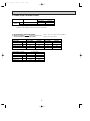
2. POWER SUPPLY & MODEL NAMES
Power supply
50Hz
Service Ref.(Indoor unit)
1ph. 220, 230, 240V
Service Ref.(Outdoor unit)
PK-1.6GKL
PK-2GKL
PU-1.6VLJA2
PU-2VJA2
—
—
3ph. 380/220, 400/230, 415/240V
Notes : 1. Power supply key V(L) … 1ph, 220, 230 240V, 50Hz
2.Primary power supplies for all indoor units are single-phase.
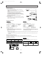
3. ELECTRICAL SPECIFICATION
(1) Rating conditions
JIS B8616,GB4706.32-96
Series PK Indoor Unit (Single Phase)
V : 220V 50Hz
Power supply (1 Phase)
Service Ref.
Current
Input
Starting courrent
PK-1.6GKL
PK-2GKL
PK-1.6GKL
PK-2GKL
0.33
0.33
0.33
0.33
KW
0.07
0.07
0.07
0.07
A
0.4
0.4
0.4
0.4
PU-1.6
PU-2
PU-1.6
PU-2
V : 240V 50Hz
Power supply (1 Phase)
Service Ref.
Input
Starting courrent
Outdoor unit
V : 230V 50Hz
A
Outdoor unit
Current
Indoor : D.B. 27°C (80°F), W.B. 19°C(66°F)
Outdoor : D.B. 35°C (95°F)
PK-1.6GKL
PK-2GKL
A
0.33
0.33
KW
0.07
0.07
A
0.4
0.4
PU-1.6
PU-2
5
OC230 --1.qxp
3
8/28/00 1:55 PM
Page 6
DATA
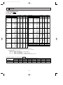
1. PERFORMANCE DATA
Cooling capacity 50Hz
PK-1.6GKL, PK-2GKL
Service Ref.
Temperature
Outdoor D.B.
21˚C
(69.8˚F)
25˚C
(77˚F)
30˚C
(86˚F)
32.2˚C
(90˚F)
35˚C
(95˚F)
40˚C
(104˚F)
Indoor W.B.
PK-1.6GKL
T.C.
C.F.
(T.I.)
PK-2GKL
T.C.
C.F.
(T.I.)
Service Ref.
Temperature
Outdoor D.B.
16˚C (60.8˚F)
18˚C (64.4˚F)
40.6˚C
19˚C (66.2˚F)
(105˚F)
19.4˚C (67˚F)
20˚C
(68˚F)
22˚C (71.6˚F)
16˚C (60.8˚F)
18˚C (64.4˚F)
45˚C
19˚C (66.2˚F)
(113˚F)
19.4˚C (67˚F)
20˚C
(68˚F)
22˚C (71.6˚F)
16˚C (60.8˚F)
18˚C (64.4˚F)
46˚C
19˚C (66.2˚F)
(115˚F)
19.4˚C (67˚F)
20˚C
(68˚F)
22˚C (71.6˚F)
16˚C (60.8˚F)
18˚C (64.4˚F)
50˚F
19˚C (66.2˚F)
(122˚F)
19.4˚C (67˚F)
20˚C
(68˚F)
22˚C (71.6˚F)
16˚C (60.8˚F)
18˚C (64.4˚F)
52˚C
19˚C (66.2˚F)
(125.5˚F)
19.4˚C (67˚F)
20˚C
(68˚F)
22˚C (71.6˚F)
Evaporator airflow (CMM)
Bypass factors
S.H.F. at rating conditions
16˚C
18˚C
19˚C
19.4˚C
20˚C
22˚C
16˚C
18˚C
19˚C
19.4˚C
20˚C
22˚C
16˚C
18˚C
19˚C
19.4˚C
20˚C
22˚C
(60.8˚F)
(64.4˚F)
(66.2˚F)
(67˚F)
(68˚F)
(71.6˚F)
(60.8˚F)
(64.4˚F)
(66.2˚F)
(67˚F)
(68˚F)
(71.6˚F)
(60.8˚F)
(64.4˚F)
(66.2˚F)
(67˚F)
(68˚F)
(71.6˚F)
3.9
4.2
4.3
4.4
4.4
4.7
3.8
4.1
4.2
4.3
4.3
4.6
3.7
3.9
4.1
4.1
4.2
4.5
0.81
0.82
0.83
0.83
0.84
0.86
0.84
0.85
0.86
0.86
0.87
0.89
0.90
0.92
0.93
0.93
0.94
0.96
5.6
6.0
6.2
6.2
6.4
6.7
5.5
5.9
6.0
6.1
6.2
6.6
5.3
5.6
5.8
5.9
6.0
6.4
0.81
0.82
0.83
0.83
0.84
0.86
0.84
0.85
0.86
0.86
0.87
0.89
0.90
0.92
0.93
0.93
0.94
0.96
16˚C
18˚C
19˚C
19.4˚C
20˚C
22˚C
16˚C
18˚C
19˚C
19.4˚C
20˚C
22˚C
16˚C
18˚C
19˚C
19.4˚C
20˚C
22˚C
(60.8˚F)
(64.4˚F)
(66.2˚F)
(67˚F)
(68˚F)
(71.6˚F)
(60.8˚F)
(64.4˚F)
(66.2˚F)
(67˚F)
(68˚F)
(71.6˚F)
3.6
3.9
4.0
4.0
4.1
4.4
3.5
3.8
3.9
4.0
4.0
4.3
0.93
0.95
0.96
0.97
0.97
0.99
0.96
0.99
1.00
1.00
1.01
1.04
5.2
5.5
5.7
5.8
5.9
6.3
5.1
5.4
5.6
5.7
5.8
6.2
0.93
0.95
0.96
0.97
0.97
0.99
0.96
0.99
1.00
1.00
1.01
1.04
(60.8˚F)
(64.4˚F)
(66.2˚F)
(67˚F)
(68˚F)
(71.6˚F)
3.4
3.6
3.7
3.8
3.9
4.1
1.03
1.06
1.07
1.08
1.08
1.11
4.9
5.2
5.4
5.4
5.5
5.9
1.03
1.06
1.07
1.08
1.08
1.11
Indoor W.B.
PK-1.6GKL
T.C.
C.F.
(T.I.)
PK-2GKL
T.C.
C.F.
(T.I.)
3.4
3.6
3.7
3.8
3.8
4.1
3.2
3.4
3.6
3.6
3.7
3.9
3.2
3.4
3.5
3.6
3.6
3.9
4.8
5.2
5.3
5.4
5.5
5.9
4.6
4.9
5.1
5.2
5.3
5.7
4.6
4.9
5.1
5.1
5.2
5.6
4.4
4.7
4.9
4.9
5.0
5.4
4.3
4.6
4.7
4.8
4.9
5.3
1.04
1.06
1.08
1.08
1.09
1.12
1.10
1.12
1.14
1.15
1.16
1.20
1.11
1.14
1.15
1.16
1.17
1.21
12
0.10
0.80
1.04
1.06
1.08
1.08
1.09
1.12
1.10
1.12
1.14
1.15
1.16
1.20
1.11
1.14
1.15
1.16
1.17
1.21
1.16
1.19
1.21
1.22
1.23
1.28
1.19
1.22
1.24
1.25
1.26
1.31
12
0.12
0.69
Notes: 1. T.C.
: Total capacity (kW) … (kcal/h)=(kW)x860, (Btu/h)=4x(kW)x860
C.F.(T.I.) : Correction factors of Total input(Indoor unit input + Outdoor unit input)
2. (°F)=32+9/5(°C)
3. Guaranteed operating range(cooling)
Lower limit … Indoor : D.B. 21°C(70°F) , W.B. 15.5°C(60°F)
Outdoor : D.B. 21°C(70°F)
Upper limit … Indoor : D.B. 35°C(95°F) , W.B. 22.5°C(72.5°F)
Outdoor : D.B. 46°C(115°F) W Outdoor : D.B. 52°C(125.5°F)…VJ,YJ
COOLING CAPACITY correction factors 50Hz
Service Ref.
PK-1.6GKL
PK-2GKL
5m (16ft)
1.0
1.0
10m (33ft)
0.992
0.985
Refrigerant piping length (one way)
15m (49ft)
20m (66ft)
25m (82ft)
30m (98ft)
0.987
0.982
—
—
0.975
0.964
0.954
0.944
6
35m (115ft)
—
—
40m (131ft)
—
—
OC230 --1.qxp
8/28/00 1:55 PM
Page 7
2. ELECTRICAL DATA
2-1 Rating conditions (JISB 8616,GB4706.32-96)
Indoor : D.B. 27°C, W.B. 19°C
Outdoor : D.B. 35°C, W.B. 24°C
Indoor unit … 220V / 230V / 240V 50Hz 1phase
Outdoor unit…220V / 230V / 240V 50Hz 1phase
Service Ref.
Indoor unit
PK-1.6GKL
Outdoor unit PU-1.6VLJA2
PK-2GKL
PK-1.6GKL
PK-2GKL
PK-1.6GKL
PK-2GKL
PU-2VJA2
PU-1.6VLJA2
PU-2VJA2
PU-1.6VLJA2
PU-2VJA2
3,900
5,600
3,900
5,600
3,900
5,600
Total Input (kW)
1.49
2.51
1.54
2.53
1.59
2.55
Input (kW)
0.07
0.07
0.07
0.07
0.07
0.07
Current (A)
0.33
0.33
0.33
0.33
0.33
0.33
Starting current (A)
0.40
0.40
0.40
0.40
0.40
0.40
Input (kW)
1.42
2.44
1.47
2.45
1.52
2.48
Current (A)
6.7
11.3
6.7
11.0
6.9
10.8
Starting current (A)
30
48
32
50
33
52
Outdoor
Indoor
Capacity (W)
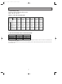
3. OUTLET AIR SPEED AND COVERAGE RANGE
PK-1.6GKL
PK-2GKL
Air flow m /min
12
12
Air speed m/sec
5.3
5.3
10(32.8)
10(32.8)
3
Coverage range m (ft)
The air coverage range is the value up to the position where the air speed is 0.25m/sec. when air is blown out horizontally from
the unit at the Hi notch position.
The coverage range should be used only as a general guideline since it varies according to the size of the room and the furniture inside the room.
7
OC230 --1.qxp
8/28/00 1:55 PM
Page 8
Total
4. STANDARD OPERATION DATA
Service Ref.
PK-1.6GKL
PK-2GKL
Mode
Cooling
Cooling
Capacity
W
3,900
5,600
Input
kW
1.49
2.51
PK-1.6GKL
PK-2GKL
1, 50
1, 50
Indoor unit Service Ref.
Electrical circuit
Phase, Hz
Volts
V
220
220
Amperes
A
0.33
0.33
PU-1.6VLJA2
PU-2VJA2
1, 50
1, 50
V
220
220
A
MPa
(kg/cm2)
MPa
(kg/cm2)
6.7
11.3
2.0
(20.6)
0.52
(5.3)
2.0
(20.4)
0.44
(4.5)
Discharge temperature
˚C
70
72
Condensing temperature
˚C
52
52
Suction temperature
˚C
7
3
Ref. pipe length
m
5
5
D.B.
˚C
27
27
W.B.
˚C
19
19
Discharge air
temperature
D.B.
˚C
14.2
11.6
Intake air
temperature
D.B.
˚C
35
35
W.B.
˚C
24
24
SHF
0.80
0.69
BF
0.10
0.12
Outdoor unit Service Ref.
Phase, Hz
Volts
Amperes
Outdoor
Indoor side
side
Refrigerant circuit
Discharge pressure
Suction pressure
Intake air
temperature
The unit of pressure has been changed to Mpa on the international system of unit (SI unit system).
The converted score against the traditional unit system can be gotten according to the formula below.
F)
1(Mpa ) = 10.2(kg/F
8
OC230 --1.qxp
8/28/00 1:55 PM
Page 9
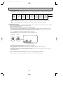
5. NOISE CRITERION CURVES
PK-1.6GKL
PK-2GKL
NOTCH SPL(dB)
Hi
43
Lo
36
LINE
OCTAVE BAND SOUND PRESSURE LEVEL, dB re 0.002 MICRO BAR
90
80
70
NC-70
60
NC-60
50
NC-50
40
NC-40
30
NC-30
20
APPROXIMATE
THRESHOLD OF
REARING FOR
CONTINUOUS
NOISE
NC-20
10
63
125
250
500
1000
2000
4000
8000
BAND CENTER FREQUENCIES, Hz
UNIT
WALL
Ambient temperature 27:
Test conditions are based on JIS Z8731
1m
1m
MICROPHONE
9
OC230 --1.qxp
8/28/00 1:55 PM
Page 10
OUTLINES AND DIMENSIONS
4
Unit : mm
1.INDOOR UNIT
PK-1.6GKL
PK-2GKL
Front view
Left side
715 Air intake
Right side
225
80
280 Air intake
53
Drain pipe.
Wiring hole.
ON STAND COOL HEAT
OFF BY
245
70 21
340
245
for left piping
Refrigerant pipe.
70 21
Knock out hole
MITSUBISHI ELECTRIC
mr.SLIm
Auto vane
60
990
Less than 15
233
198 Air intake
340 Air intake
60
for right piping
Refrigerant pipe.
Drain pipe.
Wiring hole.
235
Lower side
Knock out hole
235
705 Air outlet
160
12-Louvers(manual)
40
60
80
79
Knock out hole for under piping
Refrigerant piping.Drain pipe.
Wiring hole
50
70 35
190
400
Service panel
(Power supply access)
395
Front view(to open the grille)
Filter grip
280
Terminal block to
outdoor unit
ÅrÇoÇoÅqÅ@
ëOñ Å@ÇeÇqÇnÇmÇs
ÅrÇoÇoÅqÅ@
31
ëOñ Å@ÇeÇqÇnÇmÇs
Terminal block for
power supply
581
(Left side piping
installation)
35
54
86
449
153
700 (Flexible hose total length800)
Drain pipe (VP-20)
(Right side piping
installation)
Liquid pipe
Gas pipe
Model Liquid pipe Gas pipe
1.6 . 2
3/8F
5/8F
Allowing clearances
Front view
495
320
345
260
205
150
95
75
32
20
0
35
135
190
245
300
360
495
405
Unit center
14-[14hole
for bolts
49-[5hole
for tapping screw
30 or more
Installation plate
balance point hole
Details of installation plate
Right side
130
2.
R5
R5
Sleeve w1
[90
170
190
0
230
210
420
Model
1.6 . 2
Knock out hole for
right-rear piping
R52.5
272
310
322 w2
MITSUBISHI ELECTRIC
m r.SLIm
50 or more
150 or more
Less than 130
(Necessary clearance for
Unit installation)
425
5
2.
Knock out hole for
left-rear piping
HEAT
230
R52.5
Left-rear
piping hole
STAND COOL
BY
5
ON
OFF
190
180 or more
0
35
55
80
Right-rear
piping hole
Through hole
[90~[100
w1 Sleeves are available on the market.
w2 This size shows the lower end of through hole.
10
OC230 --1.qxp
8/28/00 1:56 PM
5
Page 11
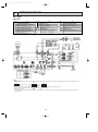
WIRING DIAGRAM
PK-1.6GKL
PK-2GKL
SYMBOL
P.B
I.B
CN2L
CN51
FC
SW1
SW2
SW3
SW5
SW6
SW7
SW8
SW9
NAME
INDOOR POWER BOARD
INDOOR CONTROLLER BOARD
CONNECTOR (LOSSNAY)
CONNECTOR (CENTRALLY CONTROL)
FAN PHASE CONTROL
SWITCH (FUNCTION SELECTOR)
SWITCH (ADDRESS SELECTOR)
SWITCH (EMERGENCY OPERATION)
SWITCH (MODEL SELECTOR)
SWITCH (TWIN / TRIPLE SELECTOR)
SWITCH (MODEL SELECTOR)
SWITCH (OPTION)
SWITCH (MODEL SELECTOR)
SYMBOL
I.B X4
F1, F2
ZNR
LED1
LED2
C
MF
MV
TB2~TB6
RT1
RT2
NAME
SYMBOL
R.B
RELAY (FAN MOTOR)
FUSE (6.3V / 250V)
CN1
VARISTOR
CN2
LED (DC 12V POWER)
SW17
LED (DC 5V POWER)
SW18
W.B
CAPACITOR (FAN MOTOR)
FAN MOTOR
RU
VANE MOTOR
BZ
TERMINAL BLOCK
LED1
ROOM TEMPERATURE THERMISTOR
SW2
(0: / 15k" , 25: / 5.4k" / DETECT)
PIPE TEMPERATURE THERMISTOR / LIQUID
(0: / 15k" , 25: / 5.4k" / DETECT)
NAME
REMOTE CONTROLLER BOARD (OPTION)
CONNECTOR (PROGRAM TIMER)
CONNECTOR (REMOTE SWITCH)
SWITCH (ADDRESS SELECTOR)
SWITCH (FUNCTION SELECTOR)
WIRELESS REMOTE CONTROLLER BOARD
RECEIVING UNIT
BUZZER
LED (RUN INDICATOR)
SWITCH (COOLING ON / OFF)
NOTES :
1. Since the indoor fan motor (MF) is connected with 230, 240V power. If 220V power is used, change the dip switch (SW8) on the indoor controller board as
shown in fig : w2.
SW8
SW8
fig w2
ON
ON
Indoor fan motor (MF)for 220V.
OFF 1 2 3 4 5 6
OFF 1 2 3 4 5 6
2. Since the outdoor side electric wiring may change be sure to check the outdoor unit electric wiring for servicing.
3. Symbols used in wiring diagram above are,
: Connector, : Terminal block.
4. Emergency operation
If remote controller or microcomputer fails but there is no other trouble , emergency operation is possible by setting dip switch (SW3<I.B>) on the indoor
controller board.
11
OC230 --1.qxp
6
8/28/00 1:56 PM
Page 12
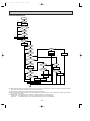
REFRIGERANT SYSTEM DIAGRAM
Unit : mm
PK-1.6GKL / PU-1.6VLJA2
PK-2GKL / PU-2VJA2
INDOOR UNIT
PK-1.6GKL
PK-2GKL
Low pressure
switch
Refrigerant pipe [15.88(5/8")
(with insulator) option
Charge
pIug
Flexible tube
Check plug
Ball
valve
Indoor heat
exchanger
OUTDOOR UNIT
PU-1.6/2J series
High pressure
switch
Outdoor heat
exchanger
Flared
connection
Flared
connection
Strainer
Distributor
Accumulator
Pipe temperature
thermistor
RT2
Compressor
Capillary tube
Ball valve
(with service port)
Refrigerant pipe [9.52(3/8")
(with insulator) option
Capillary tube
for injection
(Only PU-2VJA2)
PU-1.6 (O.D.3.2 I.D.1.8 OR900)
PU-2 (O.D.4.0 I.D.2.0 OR430)
flow of refrigerant
12
OC230 --1.qxp
7
8/28/00 1:56 PM
Page 13
OPERATION FLOW-CHART
MAIN OPERATION
START
Power circuit
breaker
1
NO
YES
YES
Check SW
ON twice
NO
Operation SW
ON
w1
YES
NO
“OFF” timer
YES
NO
NO
“ON” timer
Set time
complete
YES
YES
Set time
complete
NO
YES
w2
NO
NO
Trouble
Remote controller
operation display
YES
STOP
Trouble STOP
PROTECTION DEVICE
SELF HOLD RELEASE
PROTECTION DEVICE
SELF HOLD
w3
Remote controller
indicator lamp OFF
Remote controller
trouble display
Operating mode
(COOL)
NO
Operating mode
(DRY)
NO
YES
COOL operation
YES
DRY operation
w6
Indoor side
FAN operation
w4
Fan STOP
Outdoor side
w5
Compressor OFF
Fan STOP
w1 In addition, the centralized control and remote control can be operated.
w2 The modes which indicate the sources of trouble are listed below.
● EO-Signal transmitting/receiving error
● P1-Room temperature thermistor malfunction
● P2-Pipe temperature thermistor malfunction
● P4-Drain sensor malfunction
● P5-Drain overflow
● P6-Coil frost
● P7-System error
● P8-Outdoor unit trouble
w3 The CHECK switch will indicate if an error has occurred in the past.
w4 Fan runs on low speed for 1 minute in order to remove overheat air.
w5 The 3-minute time-delay functions after compressor stops.
w6 In FAN mode, fan speed and vane operation depend on the remote controller setting. (Compressor is OFF.)
13
OC230 --1.qxp
8/28/00 1:56 PM
Page 14
COOLING OPERATION
COOL operation
NO
Initial
COOLING
YES
Vane initial
setting
w8
Vane
50 deg downward angle
60 deg downward angle
NO
NO
YES
Fan speed
LOW
YES
Downward
discharge
1 hour
YES
NO
Vane setting notch
Vane horizontal
airflow
w9
Compressor
thermostat
ON
NO
YES
Allowance
cancel
NO
YES
3-minute
time delay
YES
6-minute
time delay
NO
3-minute
compressor
operation
NO
Allowance
period
NO
NO
w10
YES
6 minute
time delay
Coil frost protection
Allowance set
YES
YES
Coil frost
protection
NO
w11
NO
Cooling area
YES
NO
10-minute
compressor
operation
YES
Pipe
temperature is
10°C or higher
YES
Defrosting protection
detection temperature
-1°C or lower
NO
NO
YES
6-minute
time delay
YES
Indoor pipe
temperature is
1°C or lower
NO
Compressor ON
1 min continue
FAN speed
LOW
FAN speed
LOW 5 min
elapse
NO
NO
16-minute
compressor
operation
NO
YES
YES
Allowance cancel
Coil frost
prevention
NO
3-minute
time delay
YES
Outdoor unit
trouble
YES
Coil frost
prevention
Coil frost
prevention release
Compressor OFF
1
w8 When operation stops or changes to cooling or dry mode, the auto vane turns to a horizontal angle. If operation changes
during auto vane SWING, the auto vane will continue to swing.
w9 When operating TEST RUN, the thermostat will be continuously ON.
w10After 3 minute compressor operation, if the pipe temperature thermistor reads -15°C or below for 3 minutes, the compressor will stop for 6 minutes.
w11Heating area : Pipe temperature is more than 5 degrees above the room temperature.
Cooling area : Pipe temperature is more than 5 degrees below the room temperature.
FAN area
: Pipe temperature is within 5 degrees either way of the room temperature.
14
OC230 --1.qxp
8/28/00 1:56 PM
Page 15
DRY OPERATION
DRY
operation
NO
Initial dry
operation
w8
YES
Vane
setting notch
Vane initial setting
YES
w12
Room temperature is
18°C or lower
NO
NO
During
compressor ON
YES
3-minute
compressor
operation
NO
NO
YES
NO
YES
3-minute
time delay
w9
Compressor &
thermostat ON
YES
Compressor &
thermostat
ON
w9
NO
YES
NO
Compressor ON
time completes
10-minute
compressor
OFF
NO
YES
YES
w13
10-minute compressor
OFF timer start
Compressor ON
time set
Compressor OFF
Compressor ON
w14
Fan STOP
w14
Fan speed LOW
1
w8~9 Refer to page 20~21.
w12
When room temperature is 18°C or below, the compressor cannot operate.
When room temperature rises over 18°C, the compressor starts after a 3-minute time delay.
w13
Compressor ON time is decided by room temperature. Refer to page 20~21.
w14
In dry operation, compressor ON makes the fan speed LOW. Also, when the compressor OFF and the pipe temperature
is 26°C or less, the fan stops, or when the compressor OFF and the pipe temperature is below 6°C, the fan speed
changes to LOW mode.
It is not possible to set the fan speed with the remote controller.
15
OC230 --1.qxp
8
8/28/00 1:56 PM
Page 16
MICROPROCESSOR CONTROL
1. OUTLINE OF MICROPROCESSOR CONTROL
Remote controller board
INPUT to remote controller
● OFF-ON switching.
● COOL/DRY-FAN selector switching.
● Thermostat setting.
● TIMER mode selector-switching and Timer
setting.
● HIGH-LOW fan speed switching.
● AUTO Vane selector (AIR DISCHARGE)
switching.
● TEST RUN switching.
● CHECK mode switching.
(Self diagnostic trouble shooting)
● Processes and transmits
orders.
OUTPUT to remote controller
Remote controller
● LCD indicator
FILTER
CHECK MODE
TEST RUN
Non-polar, two-wire
cable maximum
length 500 meters
(WIRED only)
12VDC
Indoor unit
WIRED REMOTE
CONTROLLER (OPTION)
Signal
ADDRESS
UNIT No.
FUNCTION No.
˚C
SELECTION No.
AM
PM
FUNCTION
AM
TEST RUN
PM
CHECK
TEMP.
ON/OFF
INPUT from indoor unit
● Room temperature thermistor (RT1)
● Pipe temperature thermistor (RT2)
OUTPUT to indoor unit
Indoor controller board
● Receives orders from remote controller and
temperature data from indoor unit.
● Processes orders and data.
● Controls indoor and outdoor operation.
● Self diagnostic function.
w System control operation.
w Emergency operation.
w Set by dip switch on indoor controller board.
● Transmits the power to remote controller.
WIRELESS
REMOTE
CONTROLLER
● Auto vane’s angle setting.
● Emergency stop.
Non-polar two-wire cable
Independent Control of
Outdoor Unit
Outdoor unit
12VDC
● Compressor protection
device working
● Crankcase heater control
ON-OFF.
1
2
16
OUTPUT to outdoor unit
1 2
● Compressor and
outdoor fan : ONOFF.
OC230 --1.qxp
8/28/00 1:56 PM
Page 17
2. INDOOR UNIT CONTROL
2-1 COOL operation
<How to operate>
1 Press POWER ON/OFF button.
ADDRESS
UNIT No.
FUNCTION No.
˚C
SELECTION No.
AM
PM
FUNCTION
2 Press the MODE button to display
AM
TEST RUN
PM
CHECK
FILTER
TEMP.
CHECK MODE
3 Press the
TEMP. button to set the desired temperature.
ON/OFF
TEST RUN
NOTE: Set temperature changes 1°C when the
button is pressed one time.
Cooling 19 to 30°C
WIRED REMOTE
CONTROLLER (OPTION)
or
WIRELESS REMOTE
CONTROLLER
<COOL operation time chart>
Operation starts by
POWER button
ON.
Room temperature
becomes equal to
set temperature.
Room temperature
rises above set
temperature.
Operation stops by
POWER button
OFF.
ON
Thermostat
OFF
ON
Indoor fan
OFF
Auto vane
OFF
LOW or HIGH
LOW or HIGH
ON
ON
Compressor
OFF
Minimum 3 minutes
w1
w1 Even if the room temperature rise above the set temperature during this period, the compressor will not start until this
period has ended.
(1) Compressor control
1 3-minute time delay
To prevent overload, the compressor will not start within 3 minutes after stop.
2 The compressor runs when room temperature is higher than set temperature.
The compressor stops when room temperature is equal to or lower than the set temperature.
The compressor maintains the previous state when the discharge temperature minus the set temperature is 0°C or more, or
lower than 1°C.
3 The compressor stops in check mode or during protective functions.
4 Coil frost prevention
To prevent indoor coil frost, the compressor will stop when the pipe temperature thermistor (RT2) reads 1°C or below after
the compressor has been continuously operated for at least 16 minutes or more. When the pipe temperature rises to 10°C
or above, the compressor will start in a 3-minute(w2) time delay.
w2 When the pipe temperature is -1°C or less, the compressor starts in 6 minutes.
NOTE : By turning OFF the dip switch SW1-3 on indoor controller board, the start temperature of coil frost prevention changes
from 1°C to -3°C.
17
OC230 --1.qxp
8/28/00 1:56 PM
Page 18
5 Coil frost protection
When indoor coil temperature becomes -15°C or below,coil frost protection will proceed as follows.
<Start condition>
After the compressor has been continuously operated for 3 minutes or more,and the indoor coil temperature has been
-15°C or below for 3 minutes,the coil frost protection will start.
<Coil frost protection>
Compressor stops for 6 minutes,and then restarts.
lf the start condition is satisfied again during the first 10 minutes of compressor operation,both the indoor and outdoor
units stop, displaying a check code of “P6” on the remote controller.
<Termination conditions>
Coil frost protection is released when the start condition is not satisfied again during the allowance, or when the COOL
mode stops or changes to another mode.
(2) Indoor fan control
Indoor fan speed LOW/HIGH depends on the remote controller setting.
However, if an outdoor unit abnormality is detected, the indoor fan speed will be LOW, regardless of the remote controller
setting.
( i ) Fan speed LOW/HIGH depends on the remote controller setting regardless of the thermostat ON/OFF.
(ii) Fan speed will remain on LOW if an abnormality in outdoor unit is detected. (5 minutes)
NOTE : Fan stops immediately if the unit stops or the check mode is started.
(3) Auto vane control
Auto vane position is set to 10 degrees airflow at the start-up of COOL operation.
(a) Vane position set mode & swing mode.
( i ) Every time VANE button is pressed, setting will be changed .
( ii ) Airflow direction can be changed with VANE button.
1 Fan speed : LOW
10°
50°
60°
SWING
50°
60°
SWING
2 Fan speed : HIGH
10°
30°
<VANE POSITION>
1 Fan speed : LOW
10
2 Fan speed : HIGH
50
10
60
30
50
60
AUTO RETURN
As for the unit opreted with only wired remote controller,
When 50 degrees or 60 degrees airflow is selected with the LOW fan speed in COOL operation, “1Hr” will appear right side
of the air direction display. One hour later, the airflow direction returns to 10 degrees automatically and “1Hr” will disappear. If the airflow direction is set to 10 degrees during “1Hr” indication, the time counting for AUTO RETURN is cancelled.
18
OC230 --1.qxp
8/28/00 1:56 PM
Page 19
(4) Detecting abnormalities in the outdoor unit
After the compressor has been continuously operated for 3 minutes, if the difference between the pipe temperature and
room temperature is out of RANGE C for 1 minute, the indoor fan speed will turn to LOW. Five minutes later, if the difference is still out of RANGE C,the outdoor unit is functioning abnormally. Thus, the compressor stops and check code “P8”
appears on remote controller.
RANGE A : Pipe temperature is more than 5 degrees above room temperature.
RANGE B : Pipe temperature is within 5 degrees either way of room temperature.
RANGE C : Pipe temperature is more than 5 degrees below room temperature.
Pipe temperature
minus room temperature
(degree)
+5
0
-5
RANGE A
RANGE B
RANGE C
19
OC230 --1.qxp
8/28/00 1:56 PM
Page 20
2-2 DRY operation
ADDRESS
UNIT No.
FUNCTION No.
˚C
SELECTION No.
AM
FUNCTION
AM
TEST RUN
<How to operate>
1 Press POWER ON/OFF button.
PM
PM
CHECK
FILTER
2 Press the MODE button to display “
TEMP.
CHECK MODE
”
ON/OFF
TEST RUN
3 Press the
TEMP. button to set the desired temperature.
NOTE: The set temperature changes 1°C when the
or
button is pressed one time.
Dry 19 to 30°C
WIRED REMOTE
CONTROLLER (OPTION)
WIRELESS REMOTE
CONTROLLER
<DRY operation time chart>
Operation starts by
POWER button
ON.
Room temperature
becomes equal to
set temperature.
Room temperature
rises above set
temperature.
Operation stops by
POWER button
OFF.
ON
Thermostat
OFF
DRY MODE
DRY MODE
ON
Indoor fan
OFF
ON
Auto vane
OFF
ON
Compressor
OFF
Minimum 3 minutes w1
w1 Even if the room temperature rises above the set temperature during this period, the compressor will not start until this
period has ended.
(1) Compressor control
13-minute time delay
To prevent overload, the compressor will not start within 3 minutes after stop.
2The compressor stops in check mode or during protective functions.
20
OC230 --1.qxp
8/28/00 1:56 PM
Page 21
4The compressor will not start when the room temperature is below 18°C.
The compressor starts intermittent operation when the power is turned ON with room temperature above 18°C. The compressor ON/OFF time depends on the thermostat ON/OFF and the following room temperatures.After 3-minute compressor operation,
● If the room temperature thermistor reads above 28°C with thermostat ON, the compressor will operate for 6 more minutes and then stop for 3 minutes.
● If the room temperature thermistor reads above 26°C~28°C with thermostat ON, the compressor will operate for 4
more minutes and then stop for 3 minutes.
● If the room temperature thermistor reads 24°C~26°C with thermostat ON, the compressor will operate for 2 more minutes and then stop for 3 minutes.
● If the room temperature thermistor reads below 24°C with thermostat ON, the compressor will stop for 3 minutes.
● If the thermostat is OFF regardless of room temperature, the compressor will stop for 10 minutes.
5Coil frost protection
Coil frost protection in DRY operation is the same as in COOL operation.
6Coil frost prevention
Coil frost prevention does not operate in DRY operation.
(2) Indoor fan control
The indoor fan runs on LOW speed during compressor operation. The fan speed cannot be changed with the remote controller. Also, the fan runs on LOW speed when the pipe temperature is 6°C or more, or the compressor is OFF and the pipe
temperature is below 6°C.
(a)During compressor OFF
● When the pipe temperature is 6°C or above, the indoor fan will stop.
● When the pipe temperature is below 6°C, the indoor fan will run on LOW speed.
(b)During compressor ON
● The indoor fan runs on LOW speed.
<Dry mode>
The fan notch is controlled by the pipe temperature every 30 seconds.
Fan control in DRY operation.
Pipe temp.
Fan
6°C or more
STOP
Below 6°C
LOW
All
LOW
Compressor OFF
Compressor ON
(3) Auto vane
Same as in COOL operation
(4) Detecting abnormalities in the outdoor unit
An abnormality in the outdoor unit can not be detected in DRY operation.
21
OC230 --1.qxp
8/28/00 1:56 PM
Page 22
2-3 Auto vane control
ADDRESS
UNIT No.
FUNCTION No.
˚C
SELECTION No.
AM
PM
FUNCTION
AM
TEST RUN
PM
<How to operate>
To change the air flow direction, press VANE button.
CHECK
TEMP.
FILTER
CHECK MODE
ON/OFF
TEST RUN
WIRED REMOTE
CONTROLLER (OPTION)
1
2
3
4
10°
30°
50°
60°
WIRELESS REMOTE
CONTROLLER
1 10°
2 30° downward
Available in COOL operation with fan speed on HIGH .
Unavailable in DRY operation.
If fan speed changes from HIGH to LOW during 30°
downward airflow in COOL mode, the direction automatically changes to 10°.
3 50° downward
4 60° downward
5 swing
Changes by pressing
the VANE button.
(1) COOL/DRY operation
At the start-up of COOL or DRY operation, the airflow direction in automatically set to 10°. After, it can be changed to
another direction with VANE button on the remote controller.
<Auto return>
When 50° or 60° airflow is set with fan speed in LOW, “1Hr” appears right side of the air direction. One hour later the
direction changes to 10 degrees, automatically and “1Hr” disappears. (Only wired remote controller)
22
OC230 --1.qxp
8/28/00 1:56 PM
Page 23
2-4 TIMER operation
(1) WIRED REMOTE CONTROLLER (OPTION)
<Timer function>
AUTO STOP ·········The air conditioner stops after the set time lapses.
AUTO START ········The air conditioner starts after the set time lapses.
AUTO OFF ············Timer is not active.
<How to operate>
1. Press POWER ON/OFF button.
2. Press “ ” button to select AUTO STOP or AUTO START.
3. Press “
” button to set desired time.
Time setting is in 1 hour units for up to 24 hours.
Each time HOURS button is pressed, set time increases by 1 hour.
When HOURS button is pressed and held, the set time increases
by 1 hour every 0.5 seconds.
4. To cancel the timer operation, press POWER ON/OFF button.
FILTER
CHECK MODE
TEST RUN
<Timer setting example>
This setting will stop the air conditioner in 8 hours.
With the lapse of time, time display changes in 1 hour units, showing remaining time.
OFF
(2) WIRELESS REMOTE CONTROLLER
<How to operate>
1 Press the ON/OFF button to turn it ON.
2 Press the STOP or START button (TIMER SET).
Time can be set while the following symbol is displayed.
OFF timer : A ▼ , B
is displayed.
ON timer : A
,B
is displayed.
3 Use the HR. and MIN. buttons to set the desired time.
4 Cancelling the timer.
To cancel the OFF timer, press the STOP button.
To cancel the ON timer, press the START button.
B
·
▼
ADDRESS
UNIT No.
FUNCTION No.
A
˚C
SELECTION No.
AM
PM
FUNCTION
AM
TEST RUN
PM
CHECK
1
TEMP.
ON/OFF
START
MODE
FAN
STOP
VANE
HR.
MIN.
24
3
· It is possible to combine both OFF and ON timers.
· Pressing the ON/OFF button of the remote controller during
timer mode to stop the unit will cancel the timers.
RESET
23
OC230 --1.qxp
8/28/00 1:56 PM
Page 24
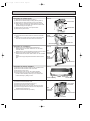
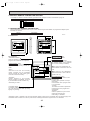
2-5 Test run
(1) WIRED REMOTE CONTROLLER (OPTION)
<Before test run>
● After installing, wiring, and piping the indoor and outdoor units, check for refrigerant leakage, looseness in power supply or
control wiring, and mistaken polarity.
● Use a 500-volt megger to check the resistance between the power supply terminal block and ground to make sure that it is
at least 1.0MΩ.
Attention:
Do not use the air conditioner if resistance is less than 1.0MΩ.
Remote controller
1
Turn on main switch.12 hours before proceeding to step 2 to allow
for crankcase heater operation.
2
Push the TEST RUN button twice and indication of TEST RUN will
be shown on the liquid crystal display.
3
Press the
blown out.
4
Push
properly.
5
Check the operation of outdoor unit fans.This unit controls the rotation speed and performance capacity of fans. ln some cases,it may
rotate at low speed as the condition of outside air requires and the
speed will be kept unless the performance has become deficient.
Therefore,when the condition of outside air demands,there may be
such cases as the fan stops or rotates reversely.
Please note that these symptoms are not malfunction.
6
After the check is finished leave the test run mode, push the power
ON/OFF button.
It can also be stopped by pushing the timer MODE button.
TEST RUN
TEST RUN button
TEST RUN Display
Indoor coil temperature code Display
button, COOL/DRY to confirm that cool air is
button LOW/HIGH to check that the fan speed changes
*The above figure shows the state of TEST
RUN at cooling operation.
●When a TEST RUN is started,the timer shall be set to 2 hours. The unit will automatically turn off after 2 hours.
(2) WIRELESS REMOTE CONTROLLER
82
ADDRESS
UNIT No.
FUNCTION No.
˚C
SELECTION No.
BA
AM
PM
FUNCTION
AM
TEST RUN
PM
CHECK
7
5
4
TEMP.
ON/OFF
START
MODE
6
FAN
STOP
VANE
HR.
MIN.
RESET
3
<Before test run>
Measure an impedance between the power supply terminal block
on the outdoor unit and the ground with a 500 V Megger and
".
check that it is equal or greater than 1.0M"
1 Turn on the main power to the unit..
2 Set the Nrm/Set selector switch (on the back of the controller)to <Set>.
AThe FUNCTION , TEST RUN and
CHECK
begin to blink.
3 Press the MIN. button.
B TEST RUN and current operation mode are displayed.
4 Press the MODE button to activate COOL
mode, then check
whether cool air in blown out from the unit.
5 Press the FAN
button and check whether strong air is blown
out from the unit.
5 Press the VANE
button and check whether the auto vane
operates properly.
7 Press the ON/OFF button to stop the test run.
8 After trial run is complete, set the Nrm/Set selector switch to <Nrm.>
Note :
Point the remote controller toward the inside unit’s receiver
while steps 3 though 7 .
It is not possible to run the unit in FAN or DRY mode.
·
·
24
OC230 --1.qxp
8/28/00 1:56 PM
Page 25
(1) Pipe temperature code
During the test run, the pipe temperature code from 1 to 15 is displayed on the remote controller instead of room temperature. The code should fall with the lapse of time in normal COOL operation.
Code
1
2
3
4
5
6
7
8
Pipe temperature
-40~2(1)°C
3(2)~10°C
~15°C
~20°C
~25°C
~30°C
~35°C
~40°C
Code
9
10
11
12
13
14
15
Pipe temperature
~45°C
~50°C
~55°C
~60°C
~70°C
~90°C
Thermistor abnormality
(2) Trouble during test run
● If the unit malfunctions during the test run, refer to section 10 in this manual entitled “TROUBLESHOOTING.”
● When the optional program timer is connected to the conditioner, refer to its operating instructions.
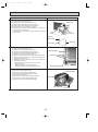
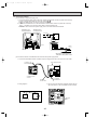
2-6 Emergency operation
When the remote controller or microprocessor malfunctions but all other parts are normal, emergency operation is started
by setting the dip switch SW3 on the indoor controller board.
<Before emergency operation>
1. Make sure the compressor and the indoor fan are operating normally.
2. Locate the defect with the self-diagnostic function. When the self-diagnostic function indicates “protective function is
working”, release the protective function before starting the emergency operation.
CAUTION: When the self-diagnostic function indicates a check code of “P5” (drain pump malfunction), DO NOT start
the emergency operation because the drain may overflow.
<How to operate>
1. For emergency cooling, set the dip switch SW3-1 to ON and SW3-2 to OFF.
Emergency
cooling
1
1 ON
2
Normal
operation
1
2
SW3
1 • 2 OFF
Microcessor board
2. Turn ON the outdoor unit breaker and then ON the indoor unit breaker.
Emergency operation will now start.
3. During emergency operation, the indoor fan operates on high speed, the auto vanes do not operate.
4. To stop emergency operation, turn OFF the indoor unit breaker.
5. Movements of the vanes do not work in emergency operation, therefore you have to slowly set them manually to the
appropriate position.
NOTE: The remote controller POWER ON/OFF button can not start/stop emergency operations.
CAUTION: Do not use emergency cooling for more than 10 hours, as the indoor coil may freeze.
25
OC230 --1.qxp
8/28/00 2:25 PM
Page 26
2-7 Interlock with ventilation system (LOSSNAY)
Mr. SLIM/LOSSNAY interlock operation is available by using the optional parts listed below.
(1) System organization
Relay box (PZ-12RB-E)
Relay box
Mr. SLIM
LOSSNAY
LOSSNAY
Power supply
Mr. SLIM
Power
supply
Remote
controller
Remote display
adapter
(PAC-SA88HA-E)
LOSSNAY control switch (PZ-05SLB2-E)
Remote
controller
LOSSNAY control switch
(PZ-05SLB2-E)
(2) LOSSNAY models connectable to Mr. SLIM are: LGH-15RS-E, LGH-50RS-E
LGH-25RS-E, LGH-80RS-E
LGH-35RS-E, LGH-100RS-E
(3) Required parts are:
● Relay box (PZ-12RB-E)…Contact capacity 10A
● Remote display adapter (PAC-SA88HA-E)…An optional part for Mr. SLIM
● LOSSNAY control switch (PZ-05SLB2-E)…For LOSSNAY individual operation
(4) Operation
1LOSSNAY turns ON/OFF according to Mr. SLIM ON/OFF
2While Mr. SLIM is OFF, LOSSNAY individual operation is available by using the LOSSNAY control switch.
When Mr. SLIM turns OFF with the LOSSNAY control switch at ON, LOSSNAY will continue to operate.
(5) Wiring.
1When the LOSSNAY control switch is used
2When the LOSSNAY control switch is not used:
Mr. SLIM
Indoor controller
board
Remote
controller
Power supply
for Mr. SLIM
220 240V AC
Relay box
(PZ-12RB-E)
LOSSNAY
Terminal block
Terminal block
A
Connector
CN51
B
L
N
HIGH
N
GRN
YLW
ORN
RED
BRN
ORN
LOW
RED
10m
Insulation
is needed
Relay box
(PZ-12RB-E)
A
B
Connecting wire
0.13mm 2 or over
Connecting wire
solid wire,
1.6 or 2.0
(field supplied)
8
ORN
L
N
WHT
RED
WHT
N
WHT
Mr.SLIM
CN51
12V DC
YLW
RED
HIGH
HIGH
Circuit
breaker
2
5
RED
DAMPER
7
6
N
L
4
N
Power supply
220 240V AC
ORN
DAMPER
WHT
3
1
Circuit breaker
(field supplied)
L
Power
supply
N
50Hz
220 240V
LOSSNAY
Terminal
block
N
L
ORN
LOW
LOW
PL
HIGH
N HIGH
N
DAMPER
DAMPER
DAMPER
LOSSNAY control switch
(PZ-05SLB 2-E)
RED
WHT
RED
ORN
WHT
NOTE: For further information, refer to the
LOSSNAY technical & service manual.
Junction box
(field supplied)
26
OC230 --1.qxp
8/28/00 1:56 PM
Page 27
2-8 Dip switch functions
Each figure shows the initial factory setting.
1. On remote controller board
(1) SW17(Address selector)
1 2 3 4 5 6 7 8
ON
OFF
SW17-1~6) For address setting
SW17-7) When two remote controllers are used,this switch sets the controller function.
OFF:The remote controller is set as a main controller.
ON :The remote controller is set as a sub controller.
SW17-8) Switch for system back-up.
OFF:Without back-up
ON :With back-up
(2) SW18(Function selector)
1 2 3 4 5 6 7 8
ON
OFF
SW18-1) Switch for timer
OFF:Single day ON:timer every day
SW18-2) Switch for filter sign
OFF:filter sign absent
ON :filter sign present
SW18-3) Switch for filter sign time setting.
OFF:100Hr ON:2500Hr
SW18-4) Not for use.
SW18-5) OFF:For models with heat pump.
ON :For models with cooling only.
SW18-6~8) Not for use.
2. On indoor controller board
(1) SW1 (Mode selector)
1 2 3 4 5 6 7 8 9 10
ON
OFF
SW1-1) Switch that changes between FAN mode and AUTO mode
OFF:AUTO mode for models with heat pump
ON :Fan mode for models with heat pump
SW1-2) Not for use.
SW1-3) Switch to change the temperature to start coil frost prevention
OFF:1°C
ON :-3°C
SW1-4) Not for use.
SW1-5) Not for use.
SW1-6) Not for use.
SW1-7) Switch for detecting abnormalities in the outdoor unit abnormality detection
OFF:When an abnormality occurs,it is detected.
ON :Even if an abnormality occurs,it can not be detected.
SW1-8) Switch for auto restart function
OFF:This function does not work
ON :This function works.
SW1-9, 10) Not for use.
27
OC230 --1.qxp
8/28/00 1:56 PM
Page 28
(2) SW2 (Address selector)
1 2 3 4 5 6
Used in setting the unit-address for group control.
For further information,refer to page 36.
ON
OFF
(3) SW3 (Emergency operation switch)
Normal operation
For emergency cooling
1 2
ON
OFF
1 2
ON
OFF
(4) SW5 (Model selector)
1 2 3 4
ON
OFF
SW5-1) Not for use.
SW5-2) OFF:For models with heat pump
ON: For models with cooling only
SW5-3) Not for use.
SW5-4) Not for use.
(5) SW6 (Address selector)
Single control
1 2 3 4
SW6-1
OFF
ON
SW6-2
OFF
OFF
Twin control
ON(Twin NO.1)
ON(Twin NO.2)
SW6-3
OFF
OFF
SW6-4
OFF
OFF
(6) SW7 (Model selector)
Switch to set the output of phase-controlled indoor fan motor.
Address setting is available at any time.
The initial factory setting by is based on each capacity.
Service Ref.
SW7
PK-1.6GKL
ON
OFF
PK-2GKL
ON
OFF
1 2 3
1 2 3
(7) SW8
1 2 3 4 5 6
ON
OFF
SW8-1~2) Not for use.
SW8-3~4) Not for use.
SW8-5) Not for use.
SW8-6) OFF:For 240, 230V power supply
ON: For 220V power supply
(8) SW9
1 2 3 4 5
ON
OFF
SW9-1~5) Keep this switch.
28
OC230 --1.qxp
9
8/28/00 1:56 PM
Page 29
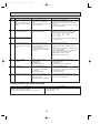
TROUBLESHOOTING
1. TROUBLES IN TEST RUN
Symptom
Cause
Check points
The display “CENTRALLY
CONTROLLED” on remote
controller dose not disappear.
1) Wrong address setting of remote controller/indoor controller board.
2) Timer adapter is connected to the
remote controller.
3) Signal transmission error between
indoor unit and remote controller.
1) Check the address setting of remote controller
and indoor controller.
2) Make sure the timer adapter is used correctly.
3) 1 Turn another remote controller’s DIP SW177 ON to make it sub controller.
2 Connect the sub controller to the unit, and
turn circuit breaker ON.
● If the display “centrally controlled” disappears, replace the original remote controller.
● If the display remains the same, replace the
indoor controller board.
When remote controller
POWER button is turned
ON, the check code
“EO”appears.
1) Signal transmission error between
indoor unit and remote controller
1) 1 Connect a sub remote controller.
2 Turn circuit breaker ON.
If the display “centrally controlled” remains,
replace the indoor controller board.
3 If the display disappears, turn the remote
controller POWER button ON and check as
follows.
Remote controller
Sub remote controller
1 Operating Display
EO Display
2 Operating Display
Operating Display
3 No Display
EO Display
4 No Display
Operating Display
Malfunction
Malfunction of
indoor Unit
Malfunction of
Remote controller
Malfunction of
indoor Unit and
Remote Controller
Malfunction of
Remote controller
When remote controller
POWER button is turned
ON, operating display
appears, but disappears
soon.
1) Short circuit of indoor/outdoor connecting wire
2) Short circuit of transmission wire.
3) Wrong operation of remote controller
due to noise wave emitted by other
appliances.
1), 2) Check the wire
3) Turn the circuit breaker OFF, and then turn
ON.
If the remote controller remains abnormal,
despite the above measures, replace the indoor
controller board.
Despite turning POWER
button ON, the remote
controller display does not
appear.
1) Damaged remote controller.
2) Short circuit of transmission wire.
3) Bad contact of indoor CN40.
4) CN40 is attached to a sub unit.
5) Damaged power board.
6) Bad contact of CN2D.
7) Blown fuse.
8) Circuit breaker OFF.
1) Measure the voltage between terminals of
remote controller. If no voltage, remove the
terminals and measure the voltage between
wires. If the voltage is between 6VDC and
12V, replace the remote controller.
2) ~ 8) Check each point.
If it is not defective, replace the indoor
controller board.
29
OC230 --1.qxp
8/28/00 1:56 PM
Page 30
2. SELF DIAGNOSTIC FUNCTION WITH REMOTE CONTROLLER
(WIRED REMOTE CONTROLLER (OPTION))
2-1 When malfunction occurs during operation
When a malfunction occurs, the indoor and outdoor units stop and the malfunction is displayed on the LCD of the remote
controller.
(1) ON the set temperature display part, “CHECK” appears, and the unit CHECK mode
address and the check code are displayed alternately at one-second
intervals. (Check mode)
Example
Check
code
Unit
address
(2) When one remote controller controls several units in the group control, the LCD shows the unit address and check code of the first malfunctioning unit.
(3) To cancel the check mode, press the ON/OFF button. In remote
ON/OFF control, press the remote ON/OFF switch. In centralized
control, turn OFF the ON/OFF button of centralized controller.
Check button
NOTE: The latest check code is memorized, even if the check mode is cancelled by the way mentioned above. It takes
60 seconds maximum to display the memorized check code.
2-2 How to use the self diagnostic function for service
A. For normal control with one unit and one remote controller
(1) Pressing the
CHECK button on the remote controller twice starts the self diagnostic function.
(2) During the self diagnostic function, “CHECK MODE” appears at two positions on the remote controller display. Then, at
least 10 seconds later, the unit address and the check code is alternately displayed at one-second intervals.
(3) Check and repair the unit according to the check code. (Refer to page 32.)
B. For group control using one remote controller
(1) Pressing the
CHECK button on the remote controller twice starts the self diagnostic function.
▲
(2) Press the
TEMP. button or ▼ TEMP. button on the remote controller to advance or go back to the unit address.
Each time ▲ TEMP. button is pressed, the unit address advances by one. Each time ▼ TEMP. button is pressed,
the unit address goes back by one.
The check code and the unit address, appear alternately.
(3) The check code “U8” means no malfunction has occurred since installation.
The check code “EO” means the following conditions:
● The unit address displayed on the remote controller does not apply to any unit.
● power is not supplied to the unit.
● Signal transmitting/receiving circuit is abnormal.
(4) Check and repair the unit according to the check code. (Refer to page 32.)
30
OC230 --1.qxp
8/28/00 1:56 PM
Page 31
(WIRELESS REMOTE CONTROLLER)
(1) Turn on the main power of the unit.
(2) Set the adjusting switch on the back of
the wireless remote controller to “Set” then
FUNCTION , TEST RUN and CHECK
will start lighting.
★(3) Press the HR. button then CHECK will
start blinking.
★(4) Send the signal from the remote controller to the unit with pressing HR. button.
If the buzzer sound is heard are the
ON/OFF lamp (Unit display) blinks, refer to
the following table.
Remove the battery cover on the back side of
the wireless remote controller, display will start
flashing when the “Set” switch is turned on.
For operations marked “ ★ ”, point the transmitter
to the wireless receiver, and make sure that you
will hear a short beep from the receiver.
Turn the adjusting switch to “Set”
ADDRESS
UNIT No.
FUNCTION No.
˚C
SELECTION No.
AM
PM
FUNCTION
AM
TEST RUN
The number of ON/OFF
lamp (Unit display) blinking
Buzzer sound
PM
CHECK
TEMP.
ON/OFF
1 second (0.5 second interval)
Beep
This corresponds to the
number of buzzer sound
START
MODE
The number of
ON/OFF lamp
(Unit display)
blinking and
buzzer sound
Irregular point
FAN
STOP
VANE
HR.
Display will start blinking
MIN.
ADDRESS
RESET
UNIT No.
FUNCTION No.
˚C
SELECTION No.
1(P1)
Irregular intake sensor
2(P2)
Irregular piping sensor
AM
PM
FUNCTION
AM
TEST RUN
PM
CHECK
3(P3)
Signal transmission error
4(P4)
Irregular drain sensor
5(P5)
Irregular drain pump
6(P6)
Freezing protection is
working
7(P7)
System error
8(P8)
Irregular outdoor unit
TEMP.
ON/OFF
(Refer to the page 32 in detail.)
When there is any error, receiving sound
beeps.
★(5)
Push the POWER ON/OFF button and
cancel the test run.
(6) After completing a test run, be sure to
For operations marked “ ★ ”, point the transmitter to the wireless
receiver, and make sure that you will hear a short beep from the
receiver.
When the other than main unit is operated by the wireless remote
controller, the receiver beeps an ineffectual beep 3-times.
31
OC230 --1.qxp
8/28/00 1:56 PM
Page 32
Check
Diagnosis of malfunction
Cause
Check points
code
EO
Signal transmitting/receiving During individual unit control
1) Check the transmission wire.
error
1) Bad contact of transmission
2) Check with another remote controller. If “EO” is
(Indoor controller does not
wire
still indicated, replace the indoor controller
respond to remote controller 2) Signal transmitting/receiving cirboard.
signal.)
cuit is abnormal.
If other check code appears. replace the original remote controller.
P1
Abnormality of room temper- 1) Bad contact of thermistor
ature thermistor (RT1)
2) Damaged thermistor
1) Check the thermistor.
2) Measure the resistance of the thermistor.
Normal resistance should be as follows.
0: ···15kΩ
30:·····4.3kΩ
10:······9.6kΩ 40: ·····3.0kΩ
20:······6.3kΩ
If the resistance is normal, replace the indoor
controller board.
P2
Abnormality of pipe temperature thermistor (RT2)
P3
Signal transmission error
(Remote controller does not
respond to indoor controller
signal.)
1) Check the transmission wire.
1) Bad contact of transmission
2) Check with another remote controller.
wire
If “P3” is still indicated, replace the indoor
2) Signal transmitting/receiving cirboard.
cuit is abnormal.
If other check code appears, replace the origi3) Wrong operation due to noise
nal remote controller.
wave emitted by other appli3) Short-circuit between 1 and 2 of CN40 and
ances
attach CN40 to the following units.
● Second unit in twin control
● Sub units in group control
P6
Freezing protection
is working.
1) Short cycle of air cycle
2) Dirty air filter
3) Damaged fan
4) Abnormal refrigerant
P7
System error
1) Wrong address-setting
1)
2) Signal transmitting/receiving cir- 2)
cuit of remote controller is
abnormal.
3) Wrong SW6-setting
3)
P8
Abnormality in outdoor unit
1) Wrong wiring of indoor/outdoor
connecting wire
2) Reversed phase
3) Protection device is working
1)
2)
3)
4)
Clear obstructions from the air cycle.
Clean the air filter
Check the fan.
Check the refrigerant temperature.
Check the address-setting.
Check with another remote controller. If check
code other than “P7” appears, replace the original remote controller.
Check SW6 setting.
1) Check the indoor/outdoor connecting wire.
2) Change the connection of electric wiring.
3) Check the protection device.
3. WHEN OUTDOOR UNIT DOES NOT WORK
Cause
1) Indoor/outdoor connecting wires are poorly connected.
2) Power supply is poorly connected.
3) Fuse (5A) in the outdoor controller board is blown.
Check points
1) Check the connecting wires.
2) Check the power supply.
3) Check the fuse.
32
OC230 --2.qxp
8/28/00 1:58 PM
Page 33
4. OTHER TROUBLES AND CAUSES
Vanes do not work.
Unit stops after 5 to
20 seconds operation
Air discharge display
is OFF and VANE
button does not operate.
In this case, remote
controller is normal.
Power ON/OFF button
is not available.
Vane motor does not work.
Connector is poorly connected.
Vane motor is poorly assembled.
Indoor controller board is damaged.
Vane motor is damaged.
Vane motor relay is damaged.
Protection function is working.
Refer to check code on remote controller display.
See page 32.
Indoor controller board
deems the auto vanes
are not attached to the
unit.
Horizontal angle can
not be detected.
Indoor controller is
damaged.
Dip switch setting is
wrong.
Indoor controller is
damaged.
Vane motor is damaged.
Auto vane is wired after
power is turned to ON.
Beep sound is heard,
but display is turned
OFF.
Vane motor is damaged.
Indoor/outdoor connecting wire is connected
incorrectly.
Indoor/outdoor connecting wire shorts.
Compressor protector
is damaged.
Outdoor controller
board is defective.
Beep sound is not heard,
and display remains OFF.
Remote controller is
damaged.
Transmission wire is
poorly connected
“CENTRALLY CONTROLLED” is displayed.
Transmission wire is
damaged.
Connector is poorly
connected.
Indoor terminal block is
poorly connected.
Remote controller terminal block is poorly
connected.
5. MR. SLIM/LOSSNAY INTERLOCK OPERATION
<Symptoms that are not malfunctions>
If any of the following symptoms occur, they are not malfunctions.
Symptom
Cause
LOSSNAY control switch does not work.
LOSSNAY control switch can not work during interlock operation.
LOSSNAY control switch is effective only while Mr. SLIM is not
operating.
LOSSNAY air speed can not be controlled in interlock operation.
LOSSNAY fan speed is fixed to HIGH during interlock operation.
LOSSNAY fan speed LOW/HIGH can be switched only during
LOSSNAY individual operation with the LOSSNAY control
switch.
For LOSSNAY, troubleshooting refer to the LOSSNAY technical & service manual.
33
OC230 --2.qxp
8/28/00 1:58 PM
Page 34
6. How to check the parts PK-1.6GKL , PK-2GKL
Parts name
Check points
Room temperature
thermistor
(RT1)
Pipe temperatuer
thermistor
(RT2)
Disconnect the connector, then measure the resistance using a tester.
(Surrounding temperature 10°C~30°C)
Normal
4.3k'~9.6k'
Abnormal
Open or short
Measure the resistance between the terminals using a tester.
Fan motor (MF)
Relay connector
3
Red
C
Black
1
Normal
PK-GKL
1.6, 2
141.2'
131.5'
Motor terminal
or
Relay connector
1
2 White
(Refer to the thermistor)
3
Red-Black
White-Black
5
Abnormal
Open or short
Protector
Vane motor (MV)
Orange
Red
M
Brown-Yellow
Brown-Blue
Red-Orange
Red-Pink
Connector
Blue
Brown
Pink
Yellow
4
5
2
Measure the resistance between the terminals using a tester.
(Surrounding temperature 20°C~30°C)
3 6 1
Normal
Abnormal
186~214'
Open or short
<Thermistor Characteristic graph>
Thermistor for
lower temperature
< Thermistor for lower temperature >
50
Room temperature thermistor(RT1)
Pipe temperature thermistor(RT2)
40
Rt=15exp { 3480(
0:
10:
20:
25:
30:
40:
1
273+t
Resistance (k")
Thermistor R0=15k' ± 3%
Fixed number of B=3480k' ± 2%
1 )}
273
30
20
15k'
9.6k'
6.3k'
5.2k'
4.3k'
3.0k'
10
0
34
-20
-10
0
10 20 30
Temperature (:)
40
50
OC230 --2.qxp
8/28/00 1:58 PM
10
Page 35
SYSTEM CONTROL
1. VARIETY OF SYSTEM CONTROL FUNCTIONS
Many units, installed at different locations, can be started
and controlled with a single remote controller. The remote
controller can be mounted in a different location using a
non-polar two-wire cable, which can be extended up to
500m. A maximum of 50 units can be controlled with a
single remote controller. All units operate in the same
mode.
1 Group control with
a single remote
controller
(See page 36.)
Unit
Unit
Unit
Remote
controller
3 Both remote
ON/OFF and individual controls
(See page 37.)
w Timer adapter
(PAC-SA89TA-E)
is needed.
Optional
adapter
Relay box
Unit
Remote
ON/OFF
switch
4 Individual control
by grouping
remote controllers
(See page 38.)
Remote
controller
Unit
Unit
By grouping the remote controllers in one place, several
units installed at different locations can be controlled individually, and operation conditions of all units are visible
without a special control board. The control method is the
same as that of the single unit with a single remote controller.
Unit
Remote
controller
5 Multiple remote
control display
(See page 39.)
w Multiple remote
controller adapter
(PAC-SA88HA-E)
is needed.
6 Auto restart
function
(See page 39.)
Unit
Remote controll
display board
Unit
All units can be turned on or off simultaneously using a
remote ON-OFF switch. Also, each unit can be controlled
individually by each remote controller. Dunning remote
ON-OFF control, a message of “CENTRALLY CONTROLLED” is displayed on the LCD of the remote controller.
This is available for both one unit control and several units
control.
Unit
Several units can be controlled with a remote control display board. Operation conditions of all the units are visible with the remote control display board.
Individual control by each remote controller is also possible.
Remote
controller
A unit can be started or stopped with the circuit breaker
on or off.
Remote controller is also available.
With this function, when the power is restored after power
failure, the unit will restart automatically. (However, when
the remote controller POWER ON/OFF button is OFF, the
unit will not start.)
Circuit breaker
Remote
controller
35
OC230 --2.qxp
8/28/00 1:58 PM
Page 36
2. GROUP CONTROL WITH A SINGLE REMOTE CONTROLLER
A maximum of 50 units can be started in order according to the dip switch settings
2-1 How to wire
Figure 1
To remote
controller
To next
unit
L N PE 1 2 3
Master unit
electrical box
To next unit
L N PE 1 2 3
(1) Connect the remote controller to the double terminal block
on the indoor controller board of the master unit (No.0 unit).
(See Figure 1.)
(2) Connect the double terminal block of the master unit to the
double terminal block of No.1 unit.
(3) Connect the double terminal block of No.1 unit to the double terminal block of No.2 unit.
(4) Continue the process until all the units are connected with
two-wire cables. (See Figure 2.)
(5) Remove the connector CN40 from the indoor controller
board of each unit except the master unit. (See Figure 3.)
(6) Set the unit-address of each unit with SW2 on the indoor
controller board following the instructions below.
Next unit
electrical box
The last unit
dose not have
this wire.
Figure 2
2-2 How to set unit-address
Master
unit
The unit-address also serves as a successive-start timer which
starts each unit at intervals of 1 second. If two or more units
have the same unit-address in a group control, operation stops
due to system error. Be sure to set SW2 correctly following the
instructions below.
(1) Each lever of SW2 shows the number as follows.
SW2-1 : 1
SW2-4 : 8
SW2-2 : 2
SW2-5 : 16
SW2-3 : 4
SW2-6 : 32
(2) Total number of levers turned to ON shows the address of
the unit.
For example, to set No.3 unit, turn ON SW2-1 and SW2-2.
(3) In this way, set from the master unit to the last unit.
Do not forget to set the master (No. 0) unit.
No.1 unit
No.2 unit
Last unit
2-wire cable
Figure 3
Indoor controller board
▼
Should be removed
from all units other
than unitNo.0:
(Master Unit).
CN40
CN40
SW2
SW2
ON
1
2
3
4
5
6
Setting examples
Master (No. 0) unit
No. 1 unit
No. 2 unit
No. 4 unit
No. 8 unit
No. 16 unit
No. 32 unit
ALL OFF
1 ON
2 ON
3 ON
4 ON
5 ON
6 ON
SW2
1
Unit address & start
delay in seconds.
2
3
4
5
6
1
0
2
3
4
5
6
1
1
2
3
4
5
6
1
2
2
3
4
5
6
1
4
2
3
4
5
6
1
8
2
3
16
4
5
6
1
2
3
4
32
2-3 Unit control
The remote controller can control all units ON/OFF, temperature, air flow, and swing louver. However, the thermostat in
each unit turns ON or OFF individually to adjust to the room temperature.
36
5
6
OC230 --2.qxp
8/28/00 1:58 PM
Page 37
3. REMOTE ON-OFF AND INDIVIDUAL REMOTE CONTROLS
This method is available to control one unit or any number of units.
The following operations are available by connecting a relay, a timer adapter (PAC-SA89TA-E), and a remote ON/OFF switch
to the system. Timer adapter is an optional part. Other parts are available on the market.
(A) To start all units in order by remote ON-OFF switch
(B) To stop all units simultaneously by remote ON-OFF switch
(C) To switch between the remote ON-OFF control and the individual remote control
3-1 System
Figure 6 shows the case of three units. The same is the case with any number of units.
Figure 6
Timer adapter
PAC-SA89TA-E
power supply of
control circuit
Remote
ON/OFF
switch
Relay box
2-wire
remote
Timer adapter cables
controller
cable
Remote
controller
NOTE1 : Install the relay box where you can be serviced it easily.
NOTE2 : For control circuit wiring, use a wire of No. 14 AWG or a control cable according to the power supply of control
circuit.
NOTE3 : When the power supply of the control circuit is 220/240V AC,
● Do not connect the control circuit wire to the remote controller cable directly.
● Do not place the control circuit wire and the remote controller cable into the same conduit tube.
3-2 Basic wiring
Caution : Before starting all units simultaneously by the remote ON-OFF switch, be sure to connect a sequence-start timer
into the remote ON-OFF circuit. Otherwise, a rush of starting current may damage the power supply.
Remote
ON/OFF
switch
Power
supply
No.1 unit
relay box
No.2 unit
relay box
SW1
Next unit
SW2
Glow switch or pilot lamp can be
combined to easily identify the
on-off mode of SW1 and SW2.
To
No.1
unit
T
T
X2
X2
T
To
No.2
unit
X2
T
X2
Remote controller
Timer adapter cables
37
OC230 --2.qxp
8/28/00 1:58 PM
Page 38
3-3 Switch function of remote ON-OFF switch
SW1
(Switches between
remote ON and OFF.)
ON
(Start)
OFF
(Stop)
SW2
(Switches between remote ON-OFF and individual control)
ON
OFF
(Remote ON-OFF control)
(Individual control)
All units start together.
w1
Each unit can be controlled by each
Individual control is not available.
remote controller.
All units stop together.
w2
Remote ON-OFF switch is not available.
Individual control is not available.
w1 After all units start together, if SW2 is turned OFF, each unit can be individually stopped by each remote controller.
w2 After all units stop together, if SW2 is turned OFF, each unit can be individually started by each remote controller.
4. INDIVIDUAL CONTROL BY GROUPING THE REMOTE CONTROLLERS
● Grouping the remote controllers allows individual control and centralized monitoring of units installed in different places without a
special control board.
● Remote control cables are extendible up to 500m. When the cable
length exceeds 12m, use the double-insulated two-care cable such
as Belden 9407. Also, the cable thickness must be No. 22 AWG or
above.
● When gathering the power ON/OFF switches of air conditioners
near the remote controllers, you should also install the power
ON/OFF switch near each unit to prevent electric trouble during
servicing.
38
Remote
controller cable (2-core)
Remote controller
OC230 --2.qxp
8/28/00 1:58 PM
Page 39
Indoor controller board
5. MULTIPLE REMOTE CONTROL DISPLAY
You can control several units with a multiple remote control display, by
wiring an optional multiple remote controller adapter (PAC-SA88HA-E) with
relays and lamps on the market.
Indoor controller board
5-1 How to wire
(1) Connect the multiple display adapter to the connector CN51 on the
indoor controller board.
(2) Wire three of the five wires from the multiple display adapter as shown
in the figure below.
<Wiring >
CN51
X2
YELLOW
X1
ORANGE
RED
Electrical insulation is needed.
BROWN
1
connector(5P)
GL
X2
GREEN
5
CN51
Optional multiple display
adapter
X1
RL
Power
supply
Wiring at the actual place
CN51
The maximum distance between
indoor board and relay is 10m.
[Notes on Signs]
X1:Relay (for operation lamp)
X2:Relay (for check lamp)
RL:Operation Lamp
GL:Check Lamp
[Field supplied parts]
Relays:12V DC with rated coil power
consumption below 0.9W.
Lamps:Matching to power supply voltage.
<System>
Power
supply
3wires
3wires
3wires
No.1 unit
2wires
Remote
controller
cable
Muitiple remote control
ON-OFF display
(Field supply)
Remote
controller
No.2 unit
No.3 unit
Relay box
(Field supply)
Remote
controller
Remote
controller
(Operation check)
<Wiring diagram>
Power
supply
RL-1
X1-1
GL-1
X2-1
RL-2
X1-2
GL-2
X2-2
RL-3
X1-3
GL-3
X2-3
X1-1
X2-1
X1-2
1
Multiple remote
controller adapter
5
No.1 unit
1
No.2 unit
X2-2
X1-3
X2-3
Multiple Remote Control Display
5
1
5
No.3 unit
connect to
the connector CN51
Relay box
6. AUTO RESTART FUNCTION
By setting the dip switch SW1-8 to ON, the air conditioner can be started/stopped by power supply ON/OFF.
If the air conditioner is OFF before the power failure, it will not start operation by power restore.
•This function is mainly to emergency performance when the power supply stops temporarily. Therefore, since the protection function (for example, clank case heater and prevention from restarting in 3 minutes, etc.) of the device is not operated, this function should not be used mostly.
7. TIMER OPERATION OR THE OPERATION BY AN EXTERNAL SIGNAL
<Wiring>
A
A
B
B
Brown
Red
A : an optional timer adapter
B : a single-throw switch
Orange
Remote controller
Brown
Red
Orange
Remote controller
For remote control, connect the optional timer adapter (PAC-SA89TA-E)
39
OC230 --2.qxp
11
8/28/00 1:58 PM
Page 40
DISASSEMBLY PROCEDURE
PK-1.6GKL
PK-2GKL
OPERATION PROCEDURE
PHOTOS & ILLUSTRATION
1. REMOVE THE LOWER SIDE OF THE INDOOR UNIT FROM
THE INSTALLATION PLATE.
(1) Remove the left / right corner box of the indoor unit.
(2) Hold and pull down the lower and both ends of the indoor
unit, and remove the ▼ section from the square hole.
(Refer to the figure 2.1)
Or remove the front panel and push the ▼ section down
by using hexagonal wrench ,etc. from the front side.
(Refer to the figure 2.2).
(3) Unhook the top of the indoor unit from the back plate
catch.
(Figure 1)
Hook
(Figure 2.1)
(Figure 2.2)
Hook
Square hole
Square hole
Up Down
(Figure 3)
2. REMOVING THE FRONT PANEL.
(1) Open the front grille.
(2) Remove the terminal block cover with a screw.
(3) Remove the screw 3 caps then remove the set 3 screws.
(4) After removing the lower side of the front panel a little,
remove it as pulling toward upper.
Terminal block cover
Front grille
(Photo 1)
Front
panel
Set screws
(Photo 2)
3. REMOVING THE INDOOR CONTROLLER BOARD.
(1) Remove the terminal block cover.
(2) Remove the front panel. (see the photo 1)
(3) Remove the electrical box(2 screws).
(4) Remove the electrical box cover(1 screw).
(5) Disconnect the connector on the controller board and
remove the controller board by pulling up the hook of the
controller case.
w To smooth works, hang the side hooks of the electrical
box on the hook of the motor cover.
(see the photo 3)
Set screw
Electrical box
Motor cover
Electrical box
hook
w
Set screw
(Photo 3)
Control board
Hook
Controller case
Electrical box
40
OC230 --2.qxp
8/28/00 2:29 PM
Page 41
OPERATION PROCEDURE
PHOTOS & ILLUSTRATION
4. REMOVING THE POWER BOARD
(1) Remove the front panel.(see the photo 1)
(2) Remove the electrical box(2 screws).(see the photo 2)
(3) Disconnect the whole connector in the control board.
(4) After lifting the controller case with pressing it’s convex
section, remove the controller case and the control board
simultaneously.(see the photo 3)
(5) Disconnect the connector in the power board.
(6) Remove the power board.
(Photo 4)
5. REMOVING THE VANE MOTOR
(1) Disconnect the connector CN6V on the indoor controller
board.
(2) Remove the 2 screws of the vane motor, disconnect the
lead wire and remove the vane motor from the shaft.
(Photo 5)
Power board
Electrical box
Nozzle
assembly
Set screws
Lead wire
Vane motor
6. REMOVING THE THERMISTOR
(1) Removing the room temperature thermistor RT1.
1Disconnect the connector CN20<red> on the indoor
controller board.
2Remove the room temperature thermistor from the holder.
(2) Removing the pipe temperature thermistor RT2.
1Disconnect the connector CN21<white> on the controller
board.
2Remove the pipe temperature thermistor with set to the
pipe.
(Photo 6)
Pipe
temperature
thermistor
Room
temperature
thermistor
Electrical box
7. REMOVING THE NOZZLE ASSEMBLY
(1) Disconnect the connector CN6V on the controller board.
(2) Disconnect the lead wire of the vane motor.
(3) Remove the corner cover.
(4) Pull the drain hose out from the nozzle assembly.
(5) Unhook the hook of the lower nozzle assembly and
pull the nozzle assembly toward you, then remove the
nozzle assembly by sliding it down.
(Photo 7)
Hooks
Nozzle assembly
8. REMOVING THE ELECTRICAL BOX
(1) Remove the terminal block cover.
(2) Remove the front panel.(see the photo 1)
(3) Disconnect the vane motor connector.
(4) Disconnect the fan motor connector from the fan motor.
(5) Remove the pipe thermistor and the room temperature
thermistor.(see the photo 6)
(6) Remove the electrical box (2 screws).
Drain hose
Corner cover
(Photo 8)
Vane motor
connector
Pipe
temperature
thermistor
Electrical box
Fan motor connector
41
OC230 --2.qxp
8/28/00 1:59 PM
Page 42
OPERATION PROCEDURE
PHOTOS & ILLUSTRATION
9. REMOVING THE FAN MOTOR.
(1) Remove the terminal block cover.
(2) Remove the front panel.(see the photo 1)
(3) Remove the electrical box.(see the photo 8)
(4) Remove the nozzle assembly.(see the photo 7)
(5) Remove the fan motor leg fixing 3 screws.
(6) Unscrew the set screws using by alankey and remove it by
sliding the fan motor to right.
(7) Remove the 4 screws and remove the motor cover from the
fan motor leg.
(Photo 9)
Motor cover
Set
screw
Fan motor
screws
(Photo 10)
Motor cover
Fan motor
10. REMOVING THE LINE FLOW FAN
(1) Remove the terminal block cover.
(2) Remove the front panel.(see the photo 1)
(3) Remove the electrical box.(see the photo 8)
(4) Remove the nozzle assembly.(see the photo 7)
(5) Remove the fan motor.(see the photo 9)
(6) Remove the pipe fixture with 2 screws.(see the photo12)
(7) Remove the left / right screws of the heat exchanger and
pull the left-hand side up.
(8) Remove the 2 screws by sliding it toward you remove the
fixture(fixing bearing).
w The fan motor is removable first , when the fan
removing is hard.
w When resetting the fan to the fan motor.
Locate and fix the shaft after installing the fan.
(Photo11)
11. REMOVING THE HEAT EXCHANGER
(1) Remove the terminal block cover.
(2) Remove the front panel.(see the photo 1)
(3) Remove the electrical box.(see the photo 8)
(4) Remove the corner box.
(5) Remove the nozzle assembly.(see the photo 7)
(6) Remove the 2 screws and the pipe fixture.
(7) Remove the 2 screws and heat exchanger.
(Photo 12)
motor leg
Heat exchanger
Set screws
Fixture(fixing bearing)
Heat exchanger
Set screw
Pipe fixture
42
Set screws
OC230 --2.qxp
8/28/00 1:59 PM
Page 43
OPERATION PROCEDURE
PHOTOS & ILLUSTRATION
(Photo 13)
12. REMOVING the SIGNAL RECEIVING P.C. BOARD
(1) Remove the terminal block cover.
(2) Disconnect the connector <yellow> for the wireless remote
Set screws
controller.
(3) Remove the front panel.(see the photo 1)
(4) Remove the 2 screws and signal receiving p.c. board cover.
(5) Remove the signal receiving p.c. board.
Front
panel
Signal receiving p.c. board cover
(Photo 14)
Front
panel
Signal receiving p.c. board
43
OC230 --2.qxp
8/28/00 1:59 PM
12
Page 44
PARTS LIST
PK-1.6GKL
PK-2GKL
19
5
6
2
4
25
9
7
15
8
30
14
1
18 31
1
12
20
28
10
23
27
3
24
22
10
11
29
26
No.
Parts No.
Parts Name
1 T7W A01 762 FAN MOTOR
2 R01 07Y 114 LINE FLOW FAN
Specifications
PM4V30-K
16 21 17
13
Wiring RecomPrice
Remarks
Diagram mended
Unit Amount
1.6GKL 2GKL (Drawing No.) Symbol Q'ty
1
1
MF
PKH-
1
1
3 R01 07Y 105 RUBBER MOUNT
4 R01 07Y 106 BEARING SUPPORT
2
2
1
1
5 R01 005 103 SLEEVE BEARING
6 R01 07Y 102 BEARING MOUNT
1
1
1
1
7 R01 07Y 130 MOTOR SUPPORT
8 T7W E13 530 NOZZLE
1
1
1
1
9 T7W E06 202 PIPE TEMPERATUER THERMISTOR
10 R01 09Y 038 GUIDE VANE
11 T7W E13 223 VANE MOTOR
1
1
4
4
1
1
12 R01 07Y 527 DRAIN HOSE
13 T7W E12 310 INDOOR CONTROLLER BOARD
1
1
1
1
I.B
1
1
F1,F2
RT2
MV
14 T7W 520 239 FUSE
15 R01 07Y 524 DRAIN PLUG
250V 6.3A
1
1
16 T7W 521 716 TERMINAL BLOCK
17 R01 588 255 CAPACITOR
3P(L, N, ;)
1
1
TB2
2.0= ✕440V
1
1
C
18 T7W E05 202 ROOM TEMPERATURE THERMISTOR
19 T7W E67 480 HEAT EXCHANGER
1
1
RT1
1
1
20 T7W E02 313 POWER BOARD
21 T7W 512 716 TERMINAL BLOCK
1
1
P.B
1
1
TB4
1
1
10
10
24 R01 07Y 059 ARM
25 T7W A00 675 FAN GUARD
2
2
1
1
26 R01 50J 317 WIRERLESS ADAPTER CONTROLLER BOARD
27
—
CONTROLLER COVER
1
1
1
1
(BG02V194H05)
28
—
CONTROLLER CASE
1
1
(BG25B573H05)
29
—
TERMINAL COVER
1
1
(BG02V195H10)
30
—
ELECTRICAL PARTS COVER
1
1
(BG00V196G20)
31
—
SENSOR HOLDER
1
1
(RG25C546H06)
22 R01 07Y 135 MOTOR COVER
23 R01 07Y 038 GUIDE VANE
2P(1, 2)
44
W.B
OC230 --2.qxp
8/28/00 1:59 PM
Page 45
STRUCTURAL PARTS
PK-1.6GKL
PK-2GKL
7
4
1
8
6
3
10
5
2
11
17
16
9
12
18
No.
Parts No.
Parts Name
Specifications
1 R01 89Y 651 FRONT PANEL
2 R01 A16 500 AIR FILTER
PK1.6 / 2
GKL
1
Remarks
(Drawing No.)
13
3
5 R01 07Y 658 CORNER COVER
6 R01 07Y 635 BOX ASSEMBLY
1
7 R01 07Y 808 BACK PLATE
8 R01 07Y 623 UNDER COVER
1
9 R01 07Y 691 FRONT GRILLE
10 R01 07Y 092 VANE SLEEVE
1
11 R01 07Y 002 AUTO VANE
12 T7W E04 714 WIRELESS REMOTE CONTROLLER
13 T7W E01 049 WIRELESS REMOTE CONTROLLER DOOR
1
14 R01 07Y 050 BATTERY COVER
15 R01 07Y 075 WIRELESS REMOTE CONTROLLER HOLDER
16 R01 24K 658 RECEIVING UNIT
1
17 T7W E04 713 REMOTE CONTROLLER
18 T7W E03 049 REMOTE CONTROLLER COVER
1
1
1
1
1
1
1
1
1
1
45
15
Wiring RecomPrice
Diagram mended
Unit Amount
Symbol Q'ty
2
3 R01 07Y 096 SCREW CAP
4 R01 09Y 658 CORNER COVER
14
RU
OC230 --2.qxp
13
8/28/00 1:59 PM
Page 46
OPTIONAL PARTS
1. REFRIGERANT PIPES
Service Ref. : PK-1.6GKL, PK-2GKL
Part No.
Pipe length
Pipe size O.D .
Connection method
PAC-05FFS-E
5m
PAC-07FFS-E
7m
Liquid:[9.52
Indoor unit: Flared
PAC-10FFS-E
10m
Gas:[15.88
Outdoor unit: Flared
PAC-15FFS-E
15m
Note 1. How to connect refrigerant pipes.
Factory supplied optional refrigerant pipings contain refrigerant at the above atmospheric pressures. As long as the
connection takes no more than 5 minutes, no air will enter, and there will be no need for air purging.
Remove the blind caps and make the connections within 5 minutes. After the connections for the indoor and outdoor
units are made, open the stop valve on the outdoor unit to allow refrigerant gas to flow.
If piping length exceeds 20m, an additional charge of refrigerant is needed.
Note 2. The following main parts are contained in the optional refrigerant piping kit.
Heat insulating cover, vinyl tapes, nipples, sleeve and flange (for wall hole).
2. TIMER
When using a program timer, PAC-SC32PTA, a program timer adapter (PAC-825AD) are and a wired remote controller
(PAR-JA240KAT-E) also needed.
Part No.
PAC-SC32PTA (with set back function)
Model Name
Program timer
2-1 Program timer specifications
Parts name
Parts No.
Exterior dimensions (inch)
Installation
Type of clock
Clock accuracy
Display-Time
-Week
-Timer setting unit
Program cycle
Timer setting unit
No. of set points
Power rating
Program timer
PAC-SC32PTA
5-4/32x4-23/32x23/32 (130x120x18mm)
Wall mount
Quartz
±50 second / month at 25°C
Liquid crystal display
Liquid crystal display
Liquid crystal display
24 hours
30 minutes
48 / day
5V DC ±5% (Supplied by Remote Controller)
2-2 Feature of program timer
(1) Daily timer function
Daily timer can be set in 30 minutes units for up to 24 hours.
Each unit can be set for unit ON, unit OFF, or setback operation.
(2) Setback operation (PAC-SC32PTA)
Set back operation is useful for reducing running costs
e.g. At a hotel with a 24-hour system
8:00~23:00 Cooling operation with set temperature at 26°C
23:00~8:00 Setback operation with 2 degrees of setback
As shown in the chart on the night, the set temperature rises 2 degrees
automatically during the setback operation. When the setback operation
ends, normal operation will begin.
(3) Weekly timer function
Daily timer function can apply to each day of the week.
46
28˚C
26˚C
8:00
Normal
operation
23:00
Setback
operation
8:00
Normal
operation
OC230 --2.qxp
8/28/00 1:59 PM
Page 47
2-3 How to connect program timer
(1) Install the program timer next to the remote controller the same way as the remote controller is installed.
(2) Connect the program timer and the remote controller with a 5-wire cable as shown in the figure below
Connect to indoor unit
2-wire cable
SET
SET
FILTER
NOTE:While the program timer is connected to the remote controller, the
24hour ON/OFF timer on the remote controller will not operate.
BACK
S M T W T F S
MONITOR
0
3
6
12
12
15
18
21
15
CHECK MODE
24
TEST RUN
SET/MONITOR
TODAY
WEEKLY
SETTING
SET BACK
ON
CLOCK
OFF
ON
DAILY
SETTING
SET BACK
DAILY TIMER
OFF
PROERAN TIMER
PAC-SC32PTA
4
Use 5-wire cable
Connect to CN1
Connect to CN1
2-4 Names and functions
<PAC-SC32PTA>
WEEKLY TIMER SETTING DISPLAY
Used for selection of if or not the day operation pattern set by PATTERN SETTING is to
be applied in weekly day unit, setting.
CURRENT TIME DISPLAY
During MONITOR status,current
time is display.
During Daily timer setting, a
time desire for timer setting is
displayed.
SET BACK DISPLAY
DAILY TIMER SETTING DISPLAY
Indicates the setting set
back range.
24 hours is divided into 48 blocks and each
block express 30 minutes.
The block display consists of 3 pattern.
Set back can be done in the range of 1,2,4,6
and 8°C.
SET BACK SETTING SW
SET
SET/MONITOR DISPLAY
SET
MONITOR
During SET is display, clock adjustment,
change of weekly day, daily and weekly timer
setting can be performed.
During MONITOR is display, all switches
except SET/MONITOR SW are invalidated.
This is normal status.
SET/MONITOR
BACK
S M T W T F S
TODAY
WEEKLY
SETTING
0
3
6
12
15
12
15
18
21
24
SET BACK
ON
ON
DAILY
SETTING
Used for set back setting.
ON/SET BACK/OFF SW
SET BACK
Used to specify the time setting pattern.
CLOCK
OFF
DAILY TIMER
OFF
PROERAN TIMER
PAC-SC32PTA
WEEK DAY SETTING SW
DAILY TIMER SW
Used for week day setting.
Used for timer setting in 30 minutes unit.
MODE SELECTOR SW
CLOCK ADJUSTMENT SW
WEEKLY TIMER SW
Using this switch select “MONITOR” or “SET”
Mode.
Used for adjustment of the current time.
Used for setting timer in day of week unit.
Push
SW to advance the time. Each time the button is
pushed the time advance by 1 minute, pushing continuously
advances by 1 minute at 0.5 second interval, and when the
lower digit of minute becomes 0 indication advances in 10 minutes unit.
SW is used for reversing the time. Each time the button is
pushed the time reverses by 1 minute, pushing continuously
reverses the time by 1 minute at 0.5 second interval, and when
the lower digit of minute becomes 0 indication reverses in 10
minutes unit.
Pushing
SW moves the week day light
display in order of
S→M→T→W…
enabling to set the week day.
“MONITOR” :Indicates the current timer setting. All switch expect MODE
SELECTOR SW are invalidated
then.This is the normal status.
“SET”: Set to “SET” mode for clock adjustment, charge of week day, daily and
weekly timer setting.
3. TIMER ADAPTER
This adapter is needed for system control and for operation via external contacts. Adapter connection is described on page 37.
Part No.
PAC-SA89TA-E
ORN
1
BRN
2
RED
3
47
OC230 --2.qxp
8/28/00 1:59 PM
Page 48
4. MULTIPLE REMOTE CONTROLLER ADAPTER
This adapter is needed for remote indication (operation/check). Adapter connection is described on page 39.
Part No.
PAC-SA88HA-E
BRN
RED
ORN
YLW
GRN
1
2
3
4
5
5. CENTRALIZED REMOTE CONTROLLER
Allows individual or combined control of up to 16 units. When using the PAC-805RC, the program timer adapter (PAC825AD)is also needed.
Part No.
PAC-805RC
Unit:mm
5-1 Dimensions
113
56.5
12
11
23.5
POWER
ON/OFF
ENGAGED
POWER
ON/OFF
ENGAGED
GROUP
DUAL CENTRAL
CONTROLLER
OPERATION
BACK
AHEAD
ACTIVE
BYPASS
1 2 3 4 5 6 7 8 9 10
DUAL
CENTRAL
GROUP
SELECTION
ACTIVE BYPASS
PROGRAM
TIMER
DUAL CENTRAL
CONTROLLER
OPERATION
BACK
AHEAD
ACTIVE
BYPASS
113
ACTIVE BYPASS
PROGRAM
TIMER
GROUP
8
GROUP
SELECTION
117
1 2 3 4 5 6 7 8 9 10
DUAL
CENTRAL
MITSUBISHI ELECTRIC
10 9 8 7 6 5 4 3 2 1
117
5-2 Functions
POWER ON/OFF switch
Operation ON/OFF switch.
"ENGAGED" indicator
When this indicator is lit, transmission is in
progress and all switches are inoperative.
DUAL/CENTRAL switch
This change-over switch governing the
operation of the accessory remote controller.
"DUAL"
Instructions from both the accessory
remote controller and the centralized
remote controller are valid. (Priority given
to the last instruction received.)
▲BACK ▼AHEAD buttons
These buttons are used to designate
the attached unit(s). (They designate
the unit to be centrally controlled.)
POWER
ON/OFF
ENGAGED
GROUP
1 2 3 4 5 6 7 8 9 10
GROUP
SELECTION
ACTIVE BYPASS
PROGRAM
TIMER
DUAL CENTRAL
CONTROLLER
OPERATION
BACK
AHEAD
ACTIVE
BYPASS
DUAL
CENTRAL
MITSUBISHI ELECTRIC
"CENTRAL"
ON/OFF switching by the accessory
remote controller is invalidated. Control is
by the centralized remote controller only.
Initial setting is "DUAL".
LCD Matrix Display
This display indicates the operational status of all connected units either by steady
lighting or by flashing.
●When group “00” is designated; collective ON/OFF instruction is sent to all
units.
●When group “01”-“16“ is designated;
ON/OFF instruction is sent to the designated units only.
ACTIVE/BYPASS switch
This is a change-over switch for the
program timer.
(It selects timer operation on the program timer.)
Use “BYPASS” when a program timer
is not connected.
“ACTIVE”
The switch turns ON/OFF operational
instructions from the program timer
automatically.
“BYPASS”
ON/OFF Operation is by the centralized remote controller only.
Initial setting is “BYPASS”.
Independent “DUAL / CENTRAL” and “ACTIVE / BYPASS” setting of all the groups is possible. When the power supply to the
centralized remote controller is cut due to power failure, all settings will return to original “DUAL” and “BYPASS”.
48
OC230 --2.qxp
8/28/00 1:59 PM
Page 49
5-3 Connection method
(1) Connections in the power supply cord.
1. Connect the power supply cord to the power supply terminal-block and fix it in-place with a tie-wrap.
Connect a single phase 200V AC (220, 230, 240V) to L N .
As E is the GND terminal, be sure to ground the earth wire.
2. Connect the transmission line to the transmission terminal-block and fix it in-place with a tie-wrap.
Use a Ω1.6 (AWG 14) or above two-wire cable for the transmission line.
CAUTION : Never connect the power supply cord to the transmission terminal-block.
TERMINAL-BLOCK
FOR TRANSMISSION
TERMINAL-BLOCK
OF POWER SUPPLY
Transmission
L
T
N
240
(Y)
(O)
230
220
(R)
200
E
(W) (BR)
Tie-wrap
5A
TRANSFORMER
Fuse(5A)
L
POWER
SUPPLY
N
Tie-wrap
E
Wiring has to be changed when
a 200,230 or 240V power is used.
(2) Connection method of centralized remote controller and power supply board.
1. Connect the centralized remote controller and power supply board with a non-polar, two-wire cable.
Power supply board box
To adaptor's
terminal-block
POWER
ON/OFF
ENGAGED
GROUP
1 2 3 4 5 6 7 8 9 10
GROUP
SELECTION
ACTIVE BYPASS
PROGRAM
TIMER
DUAL CENTRAL
CONTROLLER
OPERATION
BACK
AHEAD
ACTIVE
BYPASS
DUAL
CENTRAL
10 9 8 7 6 5 4 3 2 1
Centralized remote
controller
To adaptor's
terminal-block
Non-polar,
two-wire cable
2. Wiring diagram
3. Be sure to set the maximum address number with the
dip switch SW17 on the centralized remote controller.
POWER
ON/OFF
ENGAGED
GROUP
1 2 3 4 5 6 7 8 9 10
Centralized
remote controller
GROUP
SELECTION
ACTIVE BYPASS
PROGRAM
TIMER
DUAL CENTRAL
CONTROLLER
OPERATION
BACK
AHEAD
ACTIVE
BYPASS
DUAL
CENTRAL
Power supply
board
10 9 8 7 6 5 4 3 2 1
49
Dip switch
SW17
OC230 --2.qxp
8/28/00 1:59 PM
Page 50
6. PROGRAM TIMER ADAPTER
This adapter is needed when a program timer(PAC-SC32PTA)or a centralized remote controller(PAC-805RC)is used.
Part No.
PAC-825AD
6-1 Parts included
1 ADAPTER ·························1P
2 3-core cable···························1P
3 3-core cable···························1P
Length : 2m (6' 7")
Length : 2m (6' 7")
4 4-core cable···························1P
5 5-core cable···························1P
Length : 2m (6' 7")
Length : 2m (6' 7")
6-2 Connection method
Connection and wiring methods differ with the type of the indoor unit used. Confirm the type before carrying out the work.
(1) Connections in the adapter box.
1. Connect the power supply cord to the terminal-block and fix it in-place with a tie-wrap.
Connect a single phase 200V AC (220, 230, 240V) to L N .
As E is the GND terminal, be sure to ground the earth wire.
2. Connect the transmission line to the transmission terminal-block and fix it in-place with a tie-wrap (when a
centralized remote controller is being used).
CAUTION : Never connect the power supply cord to the transmission terminal-block
Fig.1
CN22
Dip switch
(AG)
CN1 CN21 CN51 CN30 CN42 CN50 CN40
L
N
Tie-wrap
TERMINAL-BLOCK
(W)
FOR POWER
SUPPLY
Terminal block for
E
Tie-wrap
Transmission cord
SW1
TRANS
Fuse(5A)
tr ans m i s s i on to
program timer or
centralized remote
controller
T
(B)
(Y)
220
240
TRANS
SW1
200
CN22
TERMINAL-BLOCK
FOR
TRANSMISSION
Fig.2
5A
L
POWER
SUPPLY
N
;
POWER SUPPLY CORD
TRANSFORMER
Wiring has to be changed when 200V power supply is used.
(2) When the centralized remote controller is used, set the address number with the dip switch SW1 of the
program timer adapter.
50
OC230 --2.qxp
8/28/00 1:59 PM
Page 51
(3) Connections from adaptor
Fig.3
To program timer or
centralized remote
controller
Adaptor
200~240V AC
CN30 CN50
3-core cable 2
5-core cable 5
CN51
Remote controller
Indoor unit
Max. length of each calbe is 10m.
6-3 Dimensions
(Unit : mm)
40 27 18
65
120
ho 15
le
27
8 7 74
35
15
35
22
22
12
86
220
95
Fixing screw hole
4- 5.5
230
80
70
40
15
Fig. 4
2 2- 2.9
30
200
7. Wired remote controller and terminl bed for remote controller
Part No.
PAR-JA240KAT-E
8. Remote Sensor
Part No.
PAC-SE41TS-E
51
OC230 --2.qxp
8/28/00 1:59 PM
Page 52
10. MULTI DISTRIBUTION PIPE FOR TWIN (50:50)
SDD-50S-E
Part No.
Indoor unit
Applicable Service Ref.
: PK-1.6GKL, 2GKL
Outdoor unit : PU-3,4 type
10-1 Parts included
1 Installation manual
2 Gas pipe
This sheet 1 sheet
3 Liquid pipe
4 Pipe cover (Gas pipe)
1 pc
5 Pipe cover (Liquid pipe) 6 2-core cable (12m)
1 pc
1 pc
1 pc
1 pc
7 Joint pipe
A 1pc
B 1pc
C 1pc
D 1pc
• The gas pipe 2 and liquid pipe 3 are specified as shown below.
2 Gas pipe
3 Liquid pipe
Model indication
ID {9.52
(indoor unit side)
After cutting the pipe with the pipe cutter,
deburr the pipe and clean off dirt and foreign
materials.
Tag
ID {19.05
(outdoor unit side)
ID {15.88
(indoor unit side)
ID {9.52
(outdoor unit side)
Combination of indoor/outdoor unit
Distributor pipe model
SDD-50S-E
Outdoor unit
Indoor unit
PU-3
1.6 + 1.6
PU-4
2+2
The following items must be obtain locally in
addition to the packed parts.
a Heat insulating sealing tape.
b Extension pipe for refrigerant pipe.
10-2 Pipe size and refrigerant pipe limits.
Outdoor unit
Pipe size (mm)
Actual piping leng <m>
Height deffence <m>
(Note 1)
Indoor ~
Indoor ~
Indoor ~
Indoor ~
No. of bend
Outdoor unit side Indoor unit side Outdoor unit side Indoor unit side
Outdoor
Indoor
Outdoor
Indoor
|B-CI=
H=20m
h=1m
{15.88<5/8> {15.88<5/8> {9.52<3/8> {9.52<3/8> A+B=
A+C=
or less
or less less than 8
{19.05<3/4>
30m or less 8m or less
Gas side
PU-3 type
PU-4S type
Liquid side
Note1. The number of bends in the refrigerant pipe is respectively 8 or less in the range of <A+B> <A+C>
Indoor unit side
h
Indoor unit
Indoor unit
B
C
H
Outdoor unit
Distribution pipe
(Packed part)
Outdoor unit side
A
52
OC230 --2.qxp
8/28/00 1:59 PM
Page 53
10-3 Pipe connection
(1) Note the following during work:
• Be sure to recheck the combination <Table1> and pipe size
<Table2> of the outdoor/indoor units.
• Observe the refrigerant pipe length limits and no of bend limits
<Table2>.
• Insert the refrigerant pipe (obtain locally) into the flared end of the
distributior pipe (packed) until the former pipe stops.
Use oxidization-free solder for connection when possible.
• The installation of the distributor pipe (packed) is not regulated.
• Take care to prevent dirt, foreign materials, etc., from entering the
pipe when connecting the pipe.
• After checking remove the tag from the liquid pipe 3.
(2) Piping connection
• When welding the piping, use the exclusive joint 7 as the diameters of the pipe on the outdoor unit side and the joint section differ.
(Refer to the table on the right.)
Joint pipe A / B
Liquid side
•Outdoor unit PU-3type, PU-4type
ID {9.52
ID {15.88 / 19.05
Do not bend or expend any distributor pipe
(Liquid pipe)
Gas side
•Outdoor unit PU-3type / PU-4type
Joint pipe C
10-4 Heat insulating work
Gas pipe
Liquid pipe
• Install the gas pipe 2 while aligning it with the pipe cover
4. Seal the joint area of the pipe cover 4 with heat insulating sealing tape (obtain locally).
• Install the liquid pipe 3 while aligning it with the pipe cover
5. Seal the joint area of the pipe cover 5 with heat insulating sealing tape (obtain locally).
Note:
1. Cover the entire refrigerant pipe (obtain locally) with heat insulating material If connercial heat insulating meterial is used,
it must be 12mm or thicker.
2. As the pipe covers 4 and 5 will shrink slightly due to the high temperature, allow a lap when installing the heat insulating material.
10-5 Control wiring for indoor unit
• Connect the control cables of the indoor units Nos. 1 and 2 with the enclosed 2-core cable (12m) 6.
• Connect the 2-core cable 6 to the remote controller terminal in the electrical box of each indoor unit and tighten the screws.
(The polarity is not designated.)
Twin Setting
Specifications of each control cable
A
6
Enclosed with
Prepared by site optional distributor pipe. (12m)
Control cable
Control circuit voltage
0.8mm or more
Cable thickness
Polarity
Indoor unit No.1
Terminal
block for
control
1 2
SW6 Twin type
OFF
ON
4 32 1
No.2 unit
OFF
ON
4 32 1
Indoor unit No.2
CN40 connector
Terminal block
for remote
controller
1 2
1 2
A
Terminal
block for
control
No.1 unit
DC12V
0.3mm2 or more
Not designated
Terminal block
for remote
controller
1 2
C
Enclosed with
the optional
remote controller.
1 Set DIP switch SW6.
2 Remove the short-circuit connector CN40. (Leave it connected to the No.1 unit.)
Disconnect.
Note 1: SW6 default settings are all OFF.
Note 2: The short-circuit connector CN40 is connected by
factory.
c
6
Leave it connected.
Remote
controller
Outdoor unit
53
OC230 --2.qxp
8/28/00 1:59 PM
Page 54
OC230 --2.qxp
8/28/00 1:59 PM
Page 55
OC230 --2.qxp
8/28/00 1:59 PM
Page 56
HEAD OFFICE MITSUBISHI DENKI BLDG.MARUNOUCHI TOKYO100-8310 TELEX J24532 CABLE MELCO TOKYO
cCopyright 2000 MITSUBISHI ELECTRIC ENGINEERING CO.,LTD
Issued in Aug. 2000. NO.OC230 325
Printed in Japan
New publication, effective Aug. 2000
Specifications subject to change without notice