1
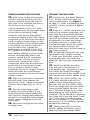
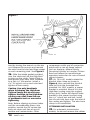
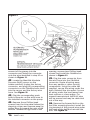
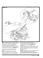
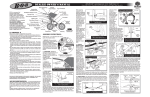
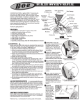
Owner’sManual
with Installation Instructions
Banks PowerPack®
TLC™ System
Including Stinger®-Plus tlc™
1998-2002 Dodge 5.9L Cummins
(24-valve) ISB Pickup Trucks
THIS MANUAL IS FOR USE WITH SYSTEMs 49320-49335 & 49351-49356
Gale Banks Engineering
546 Duggan Avenue • Azusa, ca 91702
(626) 969-9600 • Fax (626) 334-1743
Product Information & Sales: (800) 438-7693
bankspower.com
©2009 Gale Banks Engineering
12/14/09 PN 96397 v.8.0
General Installation Practices
Dear Customer,
If you have any questions
concerning the installation of
your Banks Power system, please
call our Technical Service Hotline
at (888) 839-2700 between 7:00
am and 5:00 pm (PT). If you have
any questions relating to shipping
or billing, please contact our
Customer Service Department at
(888) 839-5600.
Thank you.
1. For ease of installation of your
Banks Stinger-Plus, or PowerPack
system, familiarize yourself with the
procedure by reading the entire manual
before starting work. This instruction
manual contains 26 pages of text,
illustrations and parts listing.
2. Throughout this manual, the left side
of the vehicle refers to the driver’s side,
and the right side to the passenger’s
side.
3. Disconnect the ground cable from
the battery before beginning work. If
there are two batteries, disconnect
both.
4. Route and tie wires and hoses
a minimum of 6 inches away from
exhaust heat, moving parts and sharp
edges. Clearance of 8 inches or more
is recommended where possible.
5. When raising the vehicle, support
it on properly weight-rated safety
stands, ramps or a commercial hoist.
Follow the manufacturer’s safety
precautions. Take care to balance the
2
96397 v.8.0
vehicle to prevent it from slipping or
falling. When using ramps, be sure the
front wheels are centered squarely on
the topsides; put the transmission in
park; set the hand brake; and place
blocks behind the rear wheels.
Caution! Do not use floor jacks to
support the vehicle while working
under it. Do not raise the vehicle
onto concrete blocks, masonry
or any other item not intended
specifically for this use.
6. During installation, keep your work
area and components clean to avoid
possible dirt entry into the engine.
7. For proper performance from
your Banks PowerPack components
and to prevent engine damage, it
is essential that your engine’s fuel
system be capable of delivering fuel
at the factory’s specification. We have
often found vehicles with inadequate
low pressure side fuel delivery that
isn’t apparent until performance
modifications are made. It is very
important that the following fuel
system components are checked for
proper operation before completing
the installation.
Notification
The Banks Ram-Air Filter comes
pre-oiled and no oiling is necessary
for initial installation. Service the
filter as specified in the Filter
Maintenance Section of this
manual.
Tools Required:
These tools are necessary for all
levels of installation unless otherwise
specified.
• 1⁄ 4” and 3⁄ 8” drive ratchets with inch
and metric sockets including 5⁄ 16”,
7⁄ 16” deep 1⁄ 4” drive sockets and a 1⁄ 4”
drive extension
Highly recommended tools and
supplies (not applicable to all system
levels):
• Inch-pound and foot-pound torque
wrenches
• Inline fuel pressure test check valve
fittings
• Fuel pressure test gauge
• Inch and metric combination or
open-end wrenches
• Compressed air source and hose
• Standard and Phillips head
screwdrivers
• Rubber tipped air blow gun
• Air pressure regulator
• Standard and needle-nose pliers
• Multimeter or 12-volt test light
• Pocket or X-Acto knife
• Penetrating oil or light lubricant
spray
• Clean shop towels or rags
• Drill motor
• Tap handle
• 1⁄ 8” Allen wrench
• 3⁄ 16” and 7⁄ 16” drill bits
• 1⁄ 4” NPT tap
• Heat gun (suggested) or cigarette
lighter
• Pry bar or large groove-joint (water
pump) pliers
• Wire crimping/stripping tool
• Oxy-acetylene torch or reciprocating
saw
96397 v.8.0
3
Checking Lift Pump Performance
NOTE: Checking the lift pump
performance is required before
the installation of the your Banks
performance product. Complete the
following steps and check to see that
the fuel lift pump is operating within
specified parameters, otherwise
damage to the fuel injection pump
may occur.
FUEL FILTER AND LINES
If the fuel filter/water separator has
not been recently replaced, it is highly
recommended that this be done at
this time. Check vehicle owner’s
manual and factory service manual
for replacement intervals and service
procedure.
FUEL TRANSFER (LIFT) PUMP
The fuel transfer pump supplies fuel
from the fuel tank through the fuel
filter/water separator to the highpressure injection pump. It is a 12-volt
vane-type self-priming pump mounted
to the left side of the engine behind
Figure 1
4
96397 v.8.0
the fuel filter/water separator. Check
fuel lines to and from pump for leaks,
kinks, or other restrictions. A pump
with external housing leaks must
be replaced. Clean the area around
the pump and filter/separator before
performing the following test.
FUEL TRANSFER PUMP TEST
If a factory service manual is available,
refer to the Fuel Transfer Pump Test
in the Fuel System portion of the
manual. Otherwise perform the test as
indicated.
For ‘01-02 trucks, proceed to Step 3.
1. Remove the two hex plugs from the
top of the fuel filter/water separator
mount and replace them with two
inline check adapter fittings. Use the
fittings supplied in Banks part number
43910 test gauge kit or Parker part
number AVU1-2 Access Valve, Male
connector or equivalent. See Figure 1.
2. Install the included fuel pressure
test gauge with appropriate hose
Figure 2
fitting to the check valve installed in
the inlet port of the fuel filter mount
(This is the check valve farthest away
from the engine).
For ‘981⁄ 2-00 trucks, proceed to Step 5.
3. Remove protective cap from fuel
pressure test port fitting. See Figure
2. Clean area around cap and fitting
before removing the cap.
4. Install the included fuel pressure
test gauge onto the fuel pressure test
port fitting.
5. Prevent the engine from starting by
removing the fuel injection pump relay
in the Power Distribution Center.
6. Crank the engine and observe
the fuel pressure. Cranking pressure
should be 5-7 PSI.
7. Re-install the fuel injection pump
relay in the Power Distribution Center.
8. Start the engine and check the
pressure. It should be a minimum of
10 PSI at idle.
NOTE: If a fuel pressure of 5-7 psi
while cranking or 10 PSI with the
engine idling is not observed, this may
indicate the presence of a faulty Fuel
Lift Pump. Replace the faulty Fuel Lift
Pump or damage to the Fuel Injection
Pump may occur. 9. If a Diagnostic Trouble Code
was set when the pump relay was
removed, use a scan tool to remove
the trouble code.
10. ‘981⁄ 2-00 trucks only: Shut off the
engine and switch the fuel pressure
gauge from the inlet side check
valve to the outlet side check valve
(closest to engine). Start the engine
and observe the pressure, it should
be no more than 5 PSI lower than the
inlet pressure previously recorded. If
a greater pressure drop is observed,
replace the fuel filter. Once the
pressure test is complete, remove the
check valves and re-install the hex
plugs in the fuel filter mount.
96397 v.8.0
5
General Assembly
Figure 3
Description
1
2
3
4
5
6
7
8
9
10
11
12
13
14
15
16
17
6
High-Ram® Inlet Casting
Quick-Turbo® Turbine Housing Assembly
Monster® T.O.P. (Turbine Outlet Pipe)
Intermediate Pipe
Extension Pipe (Extended-cab Only)
Dynaflow® Muffler
Monster® Tailpipe
Tailpipe Tip
Banks Ram-Air® Filter
BigHead® Wastegate Actuator
OttoMind® TLC Engine Calibration Module
Wire Harness
Thermocouple
Leadwire, Thermocouple
DynaFact® Boost Gauge
DynaFact® Pyrometer Gauge
Wire Harness, Gauge
96397 v.8.0
18
19
20
21
22
23
24
25
26
27
28
Two-gauge Mounting Panel
Hanger Clamp
4” Exhaust Clamp (2) (extended-cabs, 3)
8” Stud (2)
83⁄ 8” Stud (2)
5⁄ 16-24 Nylock Nut (4)
5⁄ 16 AN Washer (4)
Stat-O-Seal (4)
Gasket, Inlet Casting
Gasket, Turbine Inlet
Urocal, “Banks Power” (3)
96397 v.8.0
7
System Installation Procedure
EXHAUST REMOVAL
1. Under vehicle, remove the entire
factory exhaust system. Starting
at the rear of the vehicle, remove
each component by either cutting
through the pipe near the clamps or
by removing the clamps and heating
the joints to a red-orange color to
allow the crimped pipes to separate.
Remove the pin-type hangers from
the rubber frame mounts by prying
with a pry-bar or by pressing the pin
out of the rubber with large water
pump pliers. A soapy water solution
or a penetrating lubricant will ease
the removal of pin-type hangers from
the rubber frame mounts. Remove the
two bolts that attach the turbine outlet
pipe to the turbine outlet elbow and
remove the turbine outlet pipe from
the vehicle. Keep these bolts for later
use. To remove the turbine outlet pipe,
it may be necessary to cut the pipe
just to the rear of the pin hanger that
slides into the hanger bracket on the
transmission mount.
TURBOCHARGER REMOVAL
2. Loosen the clamps that attach the
air inlet tube to the air filter housing
and to the turbocharger, and remove
the air inlet tube from the vehicle.
Remove the air filter housing from the
vehicle. This will allow easier access to
the turbocharger.
nuts or bolts and the turbocharger
from the exhaust manifold.
CAUTION: Anytime the
turbocharger is removed from
the engine, take care that no
foreign objects enter any of the
turbocharger connections on
the engine or the turbocharger.
Foreign objects entering air,
exhaust, or oil connections may
cause major damage to the engine
and/or turbocharger and is not
covered under any warranty. Cover
the open end of the intercooler
pipe with a rag, as this pipe is very
susceptible to foreign object entry.
6. Clean and inspect the exhaust
flange mounting surfaces on the
exhaust manifold. Make sure the
surface is clean and dry.
THERMOCOUPLE INSTALLATION
7. The thermocouple monitors the
temperature of the exhaust gases
entering the turbocharger at the
turbine housing. Installation requires
that the exhaust manifold be drilled
near the outlet of the manifold
adjacent to the turbine housing. For
this reason it is essential that the
turbocharger be removed from the
engine in order to clean out any metal
chips from drilling that could cause
turbine blade damage.
the turbocharger.
The Cummins ISB engine uses
a divided exhaust manifold and
turbocharger. The thermocouple
may be installed to sample exhaust
temperature in either exhaust
passage. We recommend the rear
passage (toward the firewall).
5. Note the orientation of the
8. Stuff a small shop towel or rag 4 to
3. Loosen the upper hose clamp on
the turbocharger oil drain-tube hose,
located between the two sections of
the oil drain tube.
4. Disconnect the oil supply hose at
compressor housing in the vehicle.
When the new assembly is installed
the orientation of the compressor
outlet should remain the same.
Remove the turbocharger mounting
8
96397 v.8.0
5 inches into the rear exhaust manifold
passage through the turbocharger
mounting flange. This is to prevent
chips from entering the manifold while
drilling and tapping.
9. Drill through the exhaust manifold
into the rear passage at the location
shown in Figure 4. Use a 7⁄ 16” drill,
keeping the drill perpendicular to the
manifold surface.
10. Tap the drilled hole with a 1⁄ 4”
NPT pipe tap. Check the thread
depth as you tap by periodically
removing the tap and screwing the
thermocouple into the tapped hole.
The thermocouple should thread in 3
Figure 4
96397 v.8.0
9
to 31⁄ 2 turns hand tight. Do not install
the probe in place at this time.
11. Remove as many loose chips as
back out. DO NOT use a thread locking
compound as a substitute for peening
the end of the tube. Thread locking
compounds will become ineffective
due to temperature.
possible from the exhaust manifold. A
shop vacuum, small brush or fingers
will help. Now remove the rag using a
welding rod or coat hanger bent into
a hook.
16. Using the supplied #55 bit, drill a
Caution! Make sure rags are
removed from exhaust manifold
prior to reinstalling turbocharger!
17. Reinstall the actuator on the
12. Install the thermocouple in the
manifold using anti-seize on the
threads.
Note: At this point in the installation
process, it is necessary to determine
which model turbocharger your vehicle
is equipped with. A turbocharger
identification tag is located on the front
of the compressor housing of the turbo
or on the actuator. If your turbocharger
is an HY35W, follow steps 13-17.
If your turbocharger is an HX35W,
proceed to step 18.
ACTUATOR INSTALLATION/
MODIFICATION
13. Remove the E-clip from the
wastegate arm, allowing the actuator
rod to be released. Save the E-clip
for reinstallation. Remove the two
nuts holding the actuator to the
compressor housing and remove the
actuator.
14. Tap the end of the boost
reference tube on the stock actuator
with the supplied 1⁄ 4-28 UNF tap.
Tap the tube just deep enough so
that the end of the jet is recessed
approximately 1⁄ 32” to 1⁄ 16” when
threaded into the end of the boost
reference tube and tightened until
snug.
15. Install the jet into the end of the
boost reference tube then peen the
edge of the tube so that the jet cannot
10
96397 v.8.0
hole in the side of the boost reference
tube close to the area where the tube
is attached to the actuator can.
compressor housing. Be careful not to
damage the O-ring that seals the boost
reference tube to the compressor
housing. Next, reinstall the actuator
rod end on to the wastegate arm. This
will be difficult since considerable
force is required to extend the rod far
enough. Reinstall the E-clip. Proceed
to step 23.
TURBOCHARGER DISASSEMBLY and
RE-ASSEMBLY
18. Remove the turbine discharge
elbow by removing the five bolts
around the backside of the turbo.
19. Clamp the turbine inlet flange
of the turbocharger in a smoothjaw bench vise. Loosen the four
bolts attaching the turbine housing
to the center bearing section of the
turbocharger. See Figure 5.
20. Remove the bolts, lock plates,
and clamp plates. Carefully remove
the center bearing and compressor
assembly from the cast iron turbine
housing. If the turbocharger has been
in service for some time, rust and
carbon may prevent the center bearing
and compressor assembly from easily
separating from the turbine housing.
If light hammer blows, penetrating oil
or heat will not free the compressor
assembly from the turbine housing,
the clamp bolt adjacent to the turbo oil
inlet connection may be backed out so
as to push against the bearing casting
and separate the two components.
Figure 5
Remove any loose rust or carbon from
the bearing housing that might prevent
proper engagement into the new
turbine housing.
21. Install the center bearing and
compressor assembly into the new
turbine housing. Apply a dab of antiseize compound to the bolts, and then
install bolts, clamp plates, and lock
plates finger-tight to allow for final
positioning.
22. Install the turbine outlet elbow
onto the new turbine housing using
the original bolts and the new gasket
supplied. Install the center bearing
and compressor assembly into the
new turbine housing. Apply a dab of
anti-seize compound to each of the
bolts, and then torque the bolts to
100 in-lbs. Make sure the turbine inlet
flange does not rotate in the vise while
torquing.
96397 v.8.0
11
TURBOCHARGER INSTALLATION
EXHAUST INSTALLATION
23. Note: Some turbos are mounted
27. Position the new Banks Monster
Use the supplied 3⁄ 8-24 x 13⁄ 4” bolts
and crimplock nuts for the upper holes
on the turbine mounting flange.
28. Place a 4” muffler clamp onto the
with four studs protruding from the
exhaust manifold while others have
two studs in the manifold and two in
the factory turbine housing.
Install the new turbine inlet gasket
provided and apply a dab of anti-seize
compound to the four turbo mounting
studs. Install the turbocharger on the
exhaust manifold. As the turbocharger
is reinstalled, slip the oil drain tube
into the drain hose. Tighten the
turbocharger mounting nuts to 24 ftlbs. Tighten the oil drain hose clamp.
Note: Before slipping any boost tubes
and the corresponding hoses, into
position, ensure that all connection
ends are clean and free of any oil
residue and contaminates. Clean
compressor outlet and all connection
points with a non-oil based solvent
such as Acetone, Mineral Spirits,
Denatured Alcohol or Lacquer Thinner.
Read and follow the manufactures
operation instruction for non-oil based
solvent cleaner.
24. Align the compressor outlet with
the intercooler hose adapter and
tighten the clamp. Tighten the turbine
housing clamp plate bolts to 100 inlbs.
25. Spin the turbocharger shaft
to make sure it turns freely. If not,
loosen the turbine clamp plate bolts
and check for misalignment between
the turbine housing and turbocharger
center section. Retighten bolts and
check again.
26. Reconnect and tighten the turbo
oil supply hose.
T.O.P. turbine outlet pipe onto the
turbine outlet elbow. See Figure 3
on page 6-7. Install the attaching bolts
to hold it in place, but do not tighten
them yet.
outlet of the turbine outlet pipe, and
then slide the intermediate pipe into
the hanger at the transmission mount,
and onto the turbine outlet pipe. Note:
on extended cab short bed models,
it maybe necessary to shorten the
intermediate pipe. Install the muffler
and tailpipe without clamps and
determine how much to trim based on
the hanger position.
29. On extended cab/quad-cab
long
bed models only, position another
4” clamp onto the outlet end of the
intermediate pipe, and install the
extension pipe onto the intermediate
pipe.
30. Install the muffler assembly
onto the end of the extension or
intermediate pipe. Temporarily support
the muffler and install the hanger
clamp at the front of the muffler. Snug
the nuts, but do not fully tighten them.
31. At the rear of the muffler, slip
a 4” clamp over the outlet of the
muffler. Install the tailpipe up over
the axle, and into the muffler outlet.
Place the hanger pins into the rubber
frame mounts behind the axle. Slip
the 5” Monster tailpipe tip on. Keep
the wrapping on until installation is
complete. The tip should be rotated so
the clamp nut is pointing down. Install
the 5” tip so that it hangs past the
end of the tailpipe by 1” for fleet-side
trucks and 21⁄ 2” for duallies or where
aesthetically pleasing.
32. Starting from the front of the
vehicle, tighten all exhaust system
attaching bolts and clamps. Make
12
96397 v.8.0
sure each slip joint is fully inserted,
and that all frame mount hangers are
hanging in a forward position. See
Figure 6.
For Stinger-Plus Installations, proceed
to step 38.
HIGH-RAM INSTALLATION
33. Disconnect the hose joint at the
inlet end of the factory intake casting.
Remove the dipstick tube retaining
bolt from the inlet casting. Remove
the wire loom clamp from the rear
of the inlet casting. This may break
upon removal from the casting; it is
not reused. Remove the four bolts that
mount the inlet casting to the intake
manifold and remove the factory inlet
casting. Note: at this point it may
be easier to complete the OttoMind
installation while the intake casting is
off. Cover the opening in the intake
manifold with a clean rag to prevent
foreign object entry, and proceed to
step 38. After you have completed
step 54, return to step 34
34. Remove the front inboard bolt
from the baseplate of the intake
manifold. Loosen the nut on the
ground strap for the intake heater
element and rotate the cable around
so that the ring terminal can be
reinstalled under the head of the
intake bolt. Important: do not allow
the terminal on the element end
of the ground cable to come in
contact with the upper heater lug or
with the injector line. Retighten the
retaining nut and reinstall the front
intake manifold bolt through the ring
terminal. See Figure 7.
35. Thread the four studs provided
into the intake casting, placing the
shorter studs on the inboard side.
Note: The end of the stud with the
coarse thread goes into the intake
manifold. Use Loctite sparingly on the
threads. Using the two 5⁄ 16”-24 nuts
provided, tighten the studs into the
casting by threading both nuts onto
each stud, tightening the nuts against
each other using two 1⁄ 2” open end
wrenches, and then tightening the
Figure 6
96397 v.8.0
13
Figure 7
stud by turning the wrench on the top
nut. Reverse the process and remove
the nuts from the stud and then repeat
on each remaining stud. See Figure 8.
36. Slide the intake gasket provided
over the studs and set the High-Ram™
in place on the studs. Twist a Stat-oseal washer over each stud, followed
by a flat 5⁄ 16” AN washer. Install a
5⁄ 16”-24 nylock nut on each stud and
tighten all four evenly.
Caution: Use only handtools
when tightening the High-Ram.
Tighten snugly but do not overtighten. Damage to the High-Ram
casting can result from the use
of pneumatic tools or excessive
tightening.
Note: Before slipping any boost tubes
and the corresponding hoses, into
position, ensure that all connection
ends are clean and free of any oil
residue and contaminates. Clean
14
96397 v.8.0
compressor outlet and all connection
points with a non-oil based solvent
such as Acetone, Mineral Spirits,
Denatured Alcohol or Lacquer Thinner.
Read and follow the manufactures
operation instruction for non-oil based
solvent cleaner.
37. On ‘981⁄ 2-00, models rotate the
dipstick tube clamp as shown in
Figure 8, then reinstall the dipstick
tube bolt into the threaded boss
provided. For 2001 models, a spacer
bracket is provided. Mount it to the
High-Ram casting using the original
factory bolt. Fasten the dipstick tube
bracket to the spacer bracket using
the 5⁄ 16” nylock nut and bolt. Install
the silicone inlet hose onto the inlet of
the casting and tighten. The wire loom
clamp is not reinstalled.
OTTOMIND INSTALLATION
38. For automatic transmission
models, locate and remove the rubber
Figure 8
plug mounted in the firewall slightly
above and to the right of the steering
shaft, as viewed facing the firewall
through the engine compartment.
Make a cross-shaped incision in the
plug and reinstall it in the firewall. See
Figure 9.
covering four black wires at the top
back portion of the fuel injection
pump. See Figure 10.
For manual transmission models,
make an incision in the main wiring
loom grommet above the wire bundle.
Take care to not cut any wiring. See
Figure 9.
40. At the front of the intake
Insert the black twist connector on
the OttoMind wire loom provided
through the grommet from the engine
compartment side.
39. Locate the two black wire sheaths
Caution: It is very important that
you select the proper wire. The
Banks OttoMind will not function
properly if installed incorrectly.
manifold, remove the three bolts
holding the throttle bracket assembly
to the head. Move this assembly
toward the driver’s side battery. This
will allow easier access to the fuel
pump wiring.
41. Locate a black wire tap connector
and a packet of dielectric grease in
the Banks system. Squirt a generous
96397 v.8.0
15
Figure 9
amount of the grease into the
connector and install the connector
onto the wire identified in step 39 as
shown in Figure 11.
42. Locate the Manifold Absolute
Pressure (MAP) sensor on the
intake manifold. Unplug the factory
connector, and plug the corresponding
connectors on the OttoMind wire loom
into the sensor and the factory wire
loom. See Figure 12.
43. Plug the corresponding male
bullet connector on the wire loom to
the installed connector on the pump.
44. Remove three Phillips-head
screws from the trim panel below the
steering column and remove panel by
pulling directly toward the rear of the
vehicle. Toward the right side of the
16
96397 v.8.0
opening, remove two Phillips-head
screws and install the OttoMind as
shown in Figure 13.
45. Plug the main connector from
the wire loom into the OttoMind
connector. Route all wiring away
from any pedals or other moving
components. Using the cable ties
supplied, secure the wiring under the
dash. Reinstall the trim panel. Secure
all wiring under the hood away from
heat sources or sharp edges. For
manual transmissions the blue wire
will be unused and may be cable tied
out of the way.
46. Remove the forward bolt on the
fuel filter mounting bracket. Install the
ring terminal of the ground wire under
the head of the bolt and reinstall the
bolt. See Figure 12.
Figure 10
47. Locate the gray Throttle Position
Sensor (TPS) connector just above
the injection pump. Unplug the
connector and plug both ends into
the corresponding connectors on the
OttoMind wire loom. See Figure 12.
Note: For manual transmission
applications, proceed to Step 53.
48. On automatic transmission
models, locate the PCM (rectangular
metal box with three connectors
mounted on the passenger’s
side of the firewall) in the engine
compartment. See Figure 14.
49. Make sure that the ignition is off,
then disconnect all three connectors
from the PCM for easier accessibility
to the wires.
50. Select the center (white) connector
and locate the wire in the No.11
connector pin cavity. This will typically
be an orange wire with a black
96397 v.8.0
17
Figure 11
tracer stripe. Install a T-Tap connector
on this wire approximately 2-3 inches
from the white connector body.
51. Plug the three cable connectors
back into the PCM. The connector
bodies are indexed so they cannot be
installed in the wrong location.
52. Locate the long blue wire
emerging from the middle of the Banks
OttoMind wire loom. Route this wire
with the factory wire loom across the
base of the cowl and over to the PCM.
Plug the wire into the T-Tap installed
on the No.11 pin wire at the center
PCM connector.
53. Reinstall the throttle bracket and
bolts removed earlier. Tighten to 18
ft-lbs. Reinstall the air filter housing
on the turbocharger. Iinstall the Banks
18
96397 v.8.0
Ram-Air filter.
54. Route the thermocouple leadwire
through the grommet in the firewall.
Connect the yellow and red wires
of the leadwire to the corresponding
connectors on the thermocouple. Plug
the remaining end into the proper port
on the OttoMind.
DYNAFACT INSTRUMENTATION
INSTALLATION
55. Choose a suitable location
under the lower edge of the dash
panel for mounting the instrument
panel provided where the driver can
conveniently view it. This will typically
be above and slightly to the right of
the accelerator pedal.
Figure 12
96397 v.8.0
19
Figure 13
Figure 14
20
96397 v.8.0
Note: Molded instrument consoles
for top-of-dash or pillar mount and
additional gauges are available through
Gale Banks Engineering.
c. Strip one end of the BLACK wire
and crimp it to the butt connector
containing the BLACK wires from
step ‘a’.
56. Using the panel as a template,
d. Route the RED wire to the fuse
box. Locate the appropriate fuse
for instrument lighting in the
owner’s manual. Cut the RED wire
as required and strip the end.
Crimp the push on connector
to the RED wire and connect to
the fuse as shown in Figure 15.
Alternatively, locate power wire to
dimmer switch and install T-tap.
Cut the RED wire as required and
strip the end. Crimp the push on
T-tap connector to the RED wire
and connect to T-tap on dimmer
power wire.
drill two 3⁄ 16” diameter holes in the
dash and mount the panel with two
No. 10 x 1⁄ 2” machine screws, nuts
and star washers provided.
57. Locate the gauge wire loom
with the four wire connector in the
Banks system. Plug the connector
into the corresponding location on the
OttoMind box. Route the wire loom
from the OttoMind box toward the
gauges location.
58.Install the DynaFact boost and
pyrometer gauges in the mounting
panel using the clamps and thumbnuts
provided. Plug the BLACK wire lead to
the male spade terminal on the BLACK
wire of each gauge wire harness. Plug
the YELLOW wire into the Yellow wire
of the boost gauge wire harness and
the RED wire into the RED wire of the
pyrometer gauge wire harness. The
ORANGE wire remains unused.
59. Connect the 4-pin connector
of each gauge into the back of its
corresponding gauge.
a. Crimp the remaining Black and RED
wires from each 4-pin connector
gauge harness to the butt
connectors as shown in Figure 15.
b. Strip one end of the RED wire and
crimp it to the butt connector
containing the RED wires from step
‘a’.
e. Locate a metal surface that will
serve as an acceptable chassis
ground. Cut the BLACK wire to a
sufficient length that will allow it to
reach the chassis ground and strip
the end. Crimp the ring terminal
to the BLACK wire as shown in
Figure 15.
f. Drill a 1⁄ 8” hole, if required, to
attach the ring terminal to the
chassis ground. Caution: If
drilling, check the backside
to make sure there are no
components that may be
damaged by drilling.
g. Use the supplied self-tapping screw
to secure the ring terminal to the
chassis ground
96397 v.8.0
21
Figure 15
22
96397 v.8.0
Checking Engine Performance
Go over the entire installation as a
precautionary check to ensure that
all clamps are tight, wiring and hoses
are properly routed, and connections
are tight. Start the engine and allow
it to warm up. Drive the vehicle
under light load (normal around-town
driving) for 20 to 30 minutes, and
listen for any exhaust leaks or rattles,
or intake boost leaks. Shut off the
engine and re-tighten all intercooler
and turbocharger boost clamps. These
connections may have loosened
with time, and if leaking, will cause
a drop in boost pressure with a loss
in performance. Check that clamps
are properly positioned on hoses,
and periodically check tightness of
hose clamps at regular maintenance
intervals, such as when the oil is
changed.
Observe the operation of the boost
and pyrometer gauges while driving
under varying conditions. Turbocharger
boost pressure will increase as a
function of load and engine RPM, thus
the engine will produce little boost
while cruising at light throttle, with
maximum boost while climbing hills
heavily loaded during acceleration.
Note the boost level seen during
hard acceleration with a given
load. If performance seems to have
deteriorated sometime in the future,
the maximum boost figures may be
compared to see if boost has dropped
off. Lower boost may be caused by
turbo ducting leaks, a malfunctioning
wastegate or fuel injection pump,
or dirty air filter. Typical maximum
boost pressure settings for the Dodge/
Cummins diesel will vary considerably
with stick or automatic transmission
options, year model of vehicle and
altitude.
Use your pyrometer gauge to
monitor exhaust gas temperature
(EGT) in the engine. At idle, exhaust
gas temperature will be very low,
perhaps only 300°F. As the engine
is accelerated for higher speeds
with greater loads, the EGT will rise.
The highest EGT will be seen under
maximum load at full throttle, such as
climbing a steep grade with a heavily
laden vehicle. Your pyrometer is color
coded to assist in your reading of
the gauge. The red zone indicate a
dangerous level of temperature. Your
engine should not operate in this
range for more than a few seconds.
The blue zone indicates when it is safe
to shut the engine off. To avoid heat
damage to various engine components
it is recommended that the exhaust
gases cool below 400º before the
engine is shut down.
Your OttoMind is calibrated to
maintain a maximum EGT of 1300°F.
You may experience brief excursions
slightly above 1300°F under
acceleration. This is normal and EGT
should return to at or below 1300°
within a few seconds. If you find that
EGT remains high for any length of
time, check for boost leaks or a dirty
air filter.
If you feel that your OttoMind is not
functioning properly, some diagnostics
can be performed. Remove the
OttoMind from its mounting location
while keeping all three connectors
plugged in. Observe the two LED’s
mounted on the programming port.
The upper left LED will indicate red
when the key is on. Once the engine
is started and idling, the red LED will
go out and the upper right LED will
indicate green. As load increases,
the red LED will progressively grow
brighter as fuel delivery is increased.
If LED’s do not indicate as suggested
check all connections to ensure that
they are proper.
96397 v.8.0
23
Filter Maintenance
Notification
The Banks Ram-Air Filter comes
pre-oiled and no oiling is
necessary for initial installation.
Service the filter as specified in
this Section of the manual.
1. Service Banks Ram Air Filter every
50-100,000 miles on street-driven
applications. Service more often in
off-road or heavy-dust conditions. If an
air-filter restriction gauge is installed,
then clean the element when the
air-filter restriction gauge enters the
restrictive red zone. See Figure 45.
2. Use Banks Ram Air Filter cleaning
system (part # 90094), available from
Gale Banks Engineering to service
the Air Filter. Follow the instructions
included with the cleaning system
to clean and re-oil your Banks Ram
Air Filter. No gasoline cleaning, No
steam cleaning, No caustic cleaning
solutions, No strong detergents, No
high pressure car wash, No parts
cleaning solvents. Any of these No’s
can cause harm to the cotton filter
media plus SHRINK and HARDEN the
rubber end caps.
CAUTION! Extremely fine dust from
agriculture or off-road use will pull
the oil from the element. Frequent
re-oiling of the element’s clean
side might be required. Completely
service when practicable. For extra
protection use an air-filter sealing
grease on rubber ends of the
element. Service only with Banks
Ram-Air-filter cleaner and Banks
Ram-Air-filter oil.
Figure 45 Typical air-filter restriction gauge
AIR-FILTER
RESTRICTION
GAUGE
RESTRICTIVE
RED ZONE
24
96397 v.8.0
Notes
96397 v.8.0
25
FIG #1
1
2
3
4
5
6
7
8
9
10
11
12
13
14
15
16
17
18
19
20
20
21
22
23
24
25
26
26
COMPONENTstinger-plus
CASTING, High-Ram Inlet
ASSEMBLY, Turbine Housing, Quick-Turbo®
PIPE, Turbine Outlet
PIPE, Intermediate
PIPE, Extension(Extended cab only)
MUFFLER, Banks Dynaflow®
PIPE, Monster® Tailpipe
Tailpipe Tip
FILTER, Banks Ram-Air®
ACTUATOR, BigHead®
OTTOMIND®, Engine Calibration Module
HARNESS, Wire
THERMOCOUPLE
LEADWIRE, Thermocouple
GAUGE, Boost
GAUGE, Pyrometer
HARNESS, Gauge Wiring
PANEL, Two-gauge Mounting
KIT, Service, Banks Ram-Air Filter
CLAMP, Hanger
(2) CLAMP, 4” Exhaust (Std. Cab)
(3) CLAMP, 4” Exhaust (Ext. Cab)
HOSE, Silicone
KIT, Wiring, Gauge Lighting
CONNECTOR, Wire tap
(2) BOLT, 3⁄ 8 - 24 x 13⁄ 4” HEX
(2) STUD, 8”
(2) STUD, 83⁄ 8”
(2) NUT, 3⁄ 8 - 24 Collet Lock Nut
(4) NUT, 5⁄ 16 - 24 Nylock
(2) NUT, 5⁄ 16 - 24 Standard
(2) WASHER, 3⁄ 8 A.N.
(4) WASHER, 5⁄ 16 A.N.
(4) STAT-O-SEAL
(2) CLAMP, Spring Band
GASKET, Inlet Casting
96397 v.8.0
--
3
3
3
3
3
3
3
3
--
3
3
3
3
3
3
3
3
3
3
3
3
3
3
3
3
--
--
3
--
--
3
--
--
3
--
POWERPACK
3
3*
3
3
3
3
3
3
3
-3
3
3
3
3
3
3
3
3
3
3
3
3
3
3
3*
3
3
3*
3
3
3*
3
3
3
3
FIG #1
27
28
COMPONENTstinger-plus
GASKET, Turbine Inlet GASKET, Turbine Outlet
TAP, 1⁄ 4”-28 Plug (2001 235 HP Model Only)
DRILL BIT, #55 (2001 235 HP Model Only)
JET, Actuator Tube (2001 235 HP Model Only)
ANTI-SEIZE
LOCTITE
GREASE, Dielectric
(15) TIES, 8” Cable
(6) TIES, 8” Cable
OWNERS MANUAL
WARRANTY STATEMENT, 5 year
WARRANTY STATEMENT, 2 year
WARRANTY STATEMENT, 1 year
(3) UROCAL, Banks Power
DECAL, Do Not Discard
CARD, Product Registration
*Except system #49334,49335, 59353 and 49354
3
3
--
--
--
3
---
3
3
--
3
3
3
3
3
3
3
POWERPACK
3
3*
3
3
3
3
3
3
3
-3
3
3
3
3
3
3
96397 v.8.0
27
Gale Banks Engineering
546 Duggan Avenue • Azusa, ca 91702
(626) 969-9600 • Fax (626) 334-1743
Product Information & Sales: (800) 438-7693
bankspower.com