1
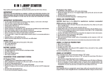
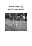
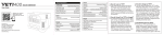
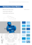
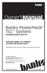
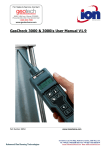
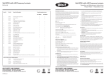
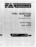
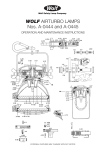
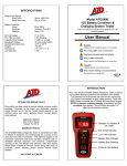
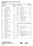
Disposable Lenses:
Anti-static lens covers W-200 (12 LED) (Pk.3) can be fitted to protect the
Worklite glass lens from damage.
Operation:
Wolf ATEX Rechargeable Worklite Range
Operation and Maintenance Instructions
Please Retain – Read Before Use
EC Declaration of Conformity
The Wolf ATEX Worklite meets all relevant provisions of the 94/9/EC
Explosive Atmospheres (ATEX Equipment) Directive by virtue of the issued
EC type examination certificate, demonstrating compliance with all relevant
harmonised standards and essential health and safety requirements.
The Wolf ATEX Worklite is a self-contained portable Worklight with a durable
construction of stainless steel and anodised aluminium enclosures. The
Worklite is powered by a sealed lead acid battery available in two sizes and
supplying arrays of 6 or 12 High Power LEDs. The Worklite range is approved
as Group II, Category 2 equipment for use in zone 1 & 2 potentially explosive
gases, vapours, mists and dusts where the T4 temperature class/135oC
maximum surface temperature permits.
Approval Codes/Certification:
II 2 GD Ex e ib mb IIC T4
Ex tD A21 IP65 T135ºC
-Press Switch Once – ON Full Power
-Press Switch Again – ON Half Power
-Press Switch Again – OFF
Battery Level Indication:
The indicator LED on the enclosure lid will indicate in the sequence as
shown in table 2. Actual indication periods may vary as a result of
temperature, charge cycle, battery condition, and electrical tolerances.
When the battery level is very low; the red indicator and beam will flash.
To assess whether a battery needs to be replaced, the duration of a full
discharge should be compared with table 1. If <70%, replace the battery.
TABLE 2:
Battery
Deep discharge protection: The lamp will automatically cut off when the
battery reaches a pre-determined low voltage. A red followed by flashing
red indicator and flashing beam will warn of imminent cut-off. The lamp
must be re-charged before further use or storage.
Storage: Due to the self-discharge characteristics of this type of Lead Acid
battery, it is imperative that it is charged every SIX months when in
storage, otherwise permanent loss of capacity might occur.
EC Type examination certificate: SIRA07ATEX3027
Notified
Body:
Replacement Battery:
WL-85
12V 33Ah pt.no. W-235 ONLY
WL-80 & WL-70
12V 18Ah pt.no. W-218 ONLY
Baseefa (2001) Ltd.
Rockhead Business Park,
Staden Lane, Buxton,
SK17 9JN, UK.
Notified body number: 1180
Head Angle Adjustment: To adjust head angle for your work area, retract
the indexing plunger and angle lamp head.
Harmonised standards applied:
Cleaning: Use a mild soap and water and soft brush only. Do not immerse.
EN60079-0:2006(+EN60079-0:2004), EN60079-7:2007(+EN60079-7:2003),
EN60079-11:2007(+EN50020:2002), EN61241-0:2006(+EN61241-0:2004),
EN61241-1:2004, EN60079-18:2004
Charging:
Use only the WL-150 Worklite Charger.
The charge socket cover must first be removed before the charger plug can
be connected.
The Worklite indicator will show flashing Red and Green at all times when
connected to a charger.
Ingress protection level: IP65 to EN60529:1992,
Wolf Worklites are certified compliant with the 2004/108/EC EMC Directive.
The product is CE marked showing compliance with all relevant EC Directives
Alex Jackson – Managing Director
Wolf Safety Lamp Company Ltd.
Use of the Wolf Worklite
First Use:
Read Instruction Manual, Remove protective switch cap and charge fully
before first use.
A damaged Worklite should be repaired in accordance with these instructions,
before being put back into service.
Repair work may ONLY be carried out by qualified technicians using
components supplied by Wolf and fitted in accordance with these instructions.
Worklite Models:
TABLE 1:
Model
Battery
Lamp
WL-85
WL-80
WL-70
12V 33 Ah
12V 18 Ah
12V 18 Ah
12 LED 1020 lm
12 LED 1020 lm
6 LED 510 lm
High Pwr
Duration
~12h
~6h
~12h
Low Pwr
Duration
Charge
Duration
~24h
~12h
~24h
~12h
~8h
~8h
The WL-150 Charger was updated in Q4 2012, check the part number on
the charger label before referring to the LED status description below. Both
chargers are compatible with all versions of the Worklite.
Charger Status LEDs – Part No AC 0412A (Pre Q4 2012)
RED = Mains power connected and charger is switched ON.
ORANGE = Charging (Cooling fan on fast speed).
GREEN = Fully Charged (Cooling fan on slow speed).
The charger continues to supply a trickle charge and can be left in this
mode on standby.
*Charger Status LEDs – Part No 31AC0412A – A03 (Post Q4 2012)
RED = Mains power connected and charger is switched ON.
ORANGE = Charging (Cooling fan on fast speed).
GREEN = Fully Charged (Cooling fan on slow speed).
The charger continues to supply a trickle charge and can be left in this
mode on standby.
*This version of the WL-150 has a system to detect when the battery in the
Worklite has reached the end of its life and cannot be charged. At the end
of the normal charging period if the RED LED is OFF and the other LED is
ORANGE or GREEN then the battery in the Worklite must be replaced.
To ensure the ingress protection level is maintained, The charge socket
cover MUST be re-fitted to the charge socket and tightened beforehand.
(Ensure area around charge socket is free from dirt)
Use of the Wolf Worklite:
Inspect the following before each use:
• Battery box lid must be closed and the four retaining screws tightened.
• Charge socket cover must be in place and tightened by hand – [This is a
certification requirement to maintain IP65]
• Cable should have no tears/splits or signs of separation from glands
• If damage is visible to any seals or the glass lens, the part must be
replaced.
Caution when handling:
Precautions should be taken when lifting and carrying heavy objects.
Following extended use, The lamp head can get hot. Do not cover head fins.
Do not stare directly into the beam as damage to the eye may occur.
W-475 Issue 5
- Do not charge in Hazardous Area.
O
O
- Charger operating ambient: +10 C to +25 C.
- Charger ingress protection IP20, protect from dirt and moisture.
- Do not cover ventilation slots.
- When charger is not in use: disconnect from mains and Worklite.
The WL-150 Charger is 'CE' marked in compliance with the 2004/108/EC
EMC Directive and 73/23/EEC Low Voltage Directive.
Peak Output Current (during charge period) = 4.0A
Peak Output Voltage (standby - fully charged) = 14.6V max
Voltage on Trickle Charge
= 13.8V
FOR APPROXIMATE CHARGE/DISCHARGE DURATIONS SEE TABLE 1
-1-
MAINTAINENCE. [Repair by qualified technicians ONLY]
Precautions should be taken when handling batteries, do not allow terminals
to short across any metal parts or objects.
Connect cables as per Fig 6. Do not allow cables to short or touch battery
terminals at any time as this may cause damage to circuit.
Removal of lamp head.
Loosen handle bolts W-433, ii) Loosen pivot bolts W-411 and whilst
supporting the head, remove pivot bolts, retract the indexer and spread the
side plates by approx 5mm lifting the head upwards and backward until it is
free and it can then be rested upside down next to the box. (Avoid pulling on
the cable)
When re-fitting lamp head, ensure threaded hole in lamp head aligns centrally
with spacer washers and hole in frame prior to fully tightening pivot bolts.
Battery Replacement WL-80 & WL-70
To replace W-218 18Ah battery in WL-80 & WL-70:
Unscrew the two terminal block retaining screws (A) to remove terminal
block and remove cross-piece retaining screws at (B). The circuit block (C),
foam block (D) and foam side piece (E) can now be removed in that order.
Disconnect vent pipe at (F) by pressing on the blue ring of the fitting while
pulling on the pipe. The Worklite box can now be tipped on to it’s side so
the battery stands upright and the top of the battery can be pulled forward
and removed from the box. Disconnect battery wires and replace battery.
Re-fitting is the reverse of the above. Ensure vent pipe is connected to
fitting under flange.
Fig 3
Torque Setting: Handle (x2) = 10.0 Nm
Torque Setting: Pivot Bolts (x2) = 6.0 Nm (Use Loctite 222 on thread)
Removal of battery enclosure lid.
Remove the four retaining screws W-405 and lift and slide the enclosure lid
rearward taking care not to pull on any of the connecting wires inside the
enclosure.
Before carrying out any work on cable, lamp, switch or indicator connections,
it is important to disconnect the battery first.
Re-fitting lid, Ensure the vent pipe is properly fitted to connections and is
tucked inside the enclosure. Ensure the lid is fitted in the correct orientation
and that seal W-300 is in place. Ensure that no wires overhang this seal, the
box edge or the battery top foam or rest directly above the battery terminals
when tightening each of the four lid retaining screws W-405. Tighten screws in
equal increments to ensure lid lowers evenly (Seal W-300 is bonded to the
enclosure)
Torque Setting: Battery Enclosure Lid Screws (x4) = 3.0Nm
Battery Replacement: WL-85
(Requires removal of both lamp head and enclosure lid)
To replace: W-235 33Ah battery in a WL-85
Fig 1
First disconnect both wires from
the battery. Disconnect the vent
pipe from the fitting under the
flange by pressing on the blue
ring to release the pipe. Remove
circuit top foam from under box
flange and disconnect vent pipe
from under flange. Lift the
encapsulated
circuit
block
assembly from alongside the
battery, remove from the box
and place next to the lid again
taking care not to snag any
cables.
To replace battery, remove foam
and spacers which surround the
circuit, slide battery forward to
release top spacer and lift
battery out taking care not to
short the battery terminals on
enclosure flange or metal tools.
Re-assembly is the reverse of
above,
See
diagram
for
foam/spacer
positions
and
orientations.
Inspect all wire
connections, connect battery
terminals. Re-connect vent pipe.
Fig 2
W-475 Issue 5
Component Replacement Procedures – Applies to all Models:
Switch Replacement:
(Requires removal of enclosure lid – see above)
i) Disconnect the switch connector. ii) Using a spanner, remove switch
locknut and push switch through lid. iii) Place new switch in lid ensuring oseal is in place, fit and tighten. iv) re-connect the 3-way connector, re-fit
any removed packing foam and replace lid as per enclosure lid removal
instructions above.
Torque Setting: Switch Locknut = 0.57Nm
Charge Socket Assembly Replacement:
(Requires removal of enclosure lid – see above)
i) Lift circuit block assembly from enclosure to gain access to terminal
block. ii) Disconnect charger socket wires (Yellow and Violet) from the
terminal block, iii) Unscrew Charge Cap and move to one side. iv) Remove
the three screws retaining the charge socket base from the underside of
the lid. v) The old base can now be lifted out and replacement fitted in the
reverse order of the above ensuring that the o-rings
are in place and in good condition. vi) Connect the
Yellow and Violet charge socket wires in to the
terminal block as shown in Fig 6.
Indicator Replacement:
(Requires removal of enclosure lid – see above)
i) Disconnect the indicator LED connector. ii) Using a
spanner, remove locknut and pull the indicator
housing through the lid, iii) grip the lower part of the
LED holder and unscrew the housing from the
assembly, iv) the LED can now be released through
the underside of the lid, Assembly is the reversal of
removal, take care not to twist or stress the cable
while screwing the lower part of the indicator to the
housing and ensure o-seals are in place, v) connect 2
way connector and assemble as above.
-2-
Glass Lens Replacement.
(Requires partial disassembly of the head) See fig 4.
i) Loosen and remove the six screws (W-414) retaining the lamp TOP plate, ii)
Partially loosen off the four lens clamp screws (W-421) until the lens is free to
move, iii) Carefully slide the old lens upwards and out, and replace with new
lens and seal, [Ensure seal fits squarely around the new lens after insertion].
iv) Gradually tighten each of the four W-421 lens screws, v) re-fit top plate
ensuring that the seal edge follows the edge of the plate and that the holes
align and that no dirt particles are present on the sealing edge. Tighten all six
screws.
Torque Setting: Top/Bottom Plate retaining Screws (x12) = 3.2Nm
Torque Setting: Lens Clamp Screws (x4) = 3.2Nm
circuit block from the enclosure if necessary. iv) Remove the locknut, and
completely remove the cable assembly from the Worklite,
v) Fitting is the reverse of the above, fit the cable gland in to enclosure lid
and lamp head bottom plate ensuring that the gland seal is external and
the shakeproof washer and locknuts are internal. vi) Connect the new cable
to the head connector block; No.1 (brown) to White, No.2 (blue) to Black
and re install the LED board, lens clamp plate and bottom plate as per the
instructions above, vii) In the battery enclosure; connect the wires in to the
connector block No.1 (brown) to White, No.2 (blue) to Black viii) Reconnect any disconnected switch or indicator cables and replace the circuit
block if necessary. When all wire connections are checked and the head
has been re-assembled, the battery can now be connected and the
enclosure lid replaced [ensuring no cables are snagged, or obstructing the
sealing edge when the lid is in position].
Torque Setting: Cable Gland Locknut = 18Nm
Fig: 4
Spare Parts List:
Part
No.
W-200
W-201
W-202
W-203
W-204
W-205
W-206
W-207
W-208
W-209
W-210
W-212
W-213
W-300
W-440
Fig: 5
Description
Used on:
3 x Antistatic Lens Guards in Bag
Cable and Gland Assembly
Battery Foam Kit 18Ah Battery
Fuse Kit: 5A & Encapsulated 1A
Battery Foam Kit 33Ah Battery
Index Plunger Kit
Head Pivot Bolts and Washer Kit
Charge Socket Cap and Chain
4 x Enclosure Lid Screws (W-415)
Lens Glass, Lens Seal & O-ring kit
Head Seal and set of Screws
Lens Glass, Lens Seal & O-ring kit
Charge Socket with Base, Seals & Screws
Battery Enclosure Lid Seal
Switch Assembly with wires/connector.
ALL
ALL
WL-70 & WL-80
ALL
WL-85
ALL
ALL
ALL
ALL
WL-85 & WL-80
ALL
WL-70
ALL
ALL
ALL
Fig: 6
LED Board Replacement:
(Requires disassembly of the head and disconnection of battery)
i) Follow “Glass Lens Replacement” steps i to iii above to remove the lens, ii)
Loosen and remove the screws (W-404) retaining the LED board. Remove the
two right-hand lens screws completely and now remove the six W-414 screws
retaining the lamp bottom plate, iii) The LED board, lower plate, clamping
plate and connector block can now all be separated from the head. [Take care
not to damage the LED lenses when handling], iv) the LED board can now be
disconnected from the connector block and the new LED board connected
(White to No.1 (or brown), Black to No.2 (or blue) v) feed the LED board up in
to the head and ensure that the thermal interface sheet W-428 for WL-85 and
WL-80 (or W-429 for WL70) is in position with holes aligned. Insert and tighten
screws W-404 and line up the lens clamp threaded holes with the screws,
Partially tighten, Fit bottom plate and tighten the six screws, vi) Re-assemble
as per iii, iv and v from ‘Glass Lens Replacement’. See Fig: 5.
Note: THERMAL GASKET MUST ALWAYS BE USED
Disconnect battery before maintenance to any of the Worklite circuit.
Torque Setting: LED PCB Screws (x4) = 2.5Nm
For re-assembly; ensure all foam blocks are correctly inserted as per fig 2 /
fig 3, and re-fit lid.
Control Circuit Replacement:
(Requires removal of enclosure lid – see above)
Disconnect the Battery. ii) At the terminal block; disconnect Lamp Output
wires identified as ‘1’ and ‘2’ (or ‘blue/brown) and Yellow and Violet (charge
socket) and also the two connectors to the switch and the indicator LED. The
circuit block can now be removed and the new Circuit fitted, see Fig: 6 for
connections. Always connect the battery last.
A short charge with charger WL-150 will be required each time a
battery is re-connected before the lamp will light.
Torque Setting: Terminal Block Screws = 0.5Nm
Model
Description
WL-85
WL-80
WL-70
12V 35 Ah 12 LED
12V 18 Ah 12 LED
12V 18 Ah 6 LED
Battery Pt
No:
W-235
W-218
W-218
Circuit Spare
Pt No:
W-494
W-534
W-495
Cable Replacement
ONLY USE GENUINE WOLF REPLACEMENT PARTS
(Requires disassembly of the head and disconnection of battery)
i) Follow steps i to iii from ‘LED Board Replacement’, ii) Disconnect terminal
block from cable assembly and using a spanner, remove the cable gland
locknut and remove the cable gland from the bottom plate. iii) Disconnect the
cable from the terminal block, tilt the battery enclosure top-plate to expose the
cable gland locknut, If necessary, disconnect the switch and indicator, lift the
W-475 Issue 5
WARNING:
• USE ONLY WOLF CHARGERS WITH THESE PRODUCTS
• USE ONLY GENUINE WOLF REPLACEMENT PARTS.
• LAMP MUST NOT BE USED WITHOUT BATTERY SPACERS AND
PACKING CORRECTLY IN POSITION
• LAMP MUST NOT BE USED WITHOUT CHARGE CAP FITTED
The Wolf Safety Lamp Co. Ltd has a policy of continuous product
improvement. Changes in design details may be made without prior notice.
Wolf Safety Lamp Company
Saxon Road Works, Sheffield, S8 0YA
Tel: +44 114 255 1051 Fax: +44 114 255 7988
E-mail: [email protected] Website: www.wolf-safety.co.uk
-3-