1
UNIT LOCATION
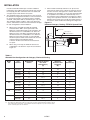
Unit Mounting
3. Be sure the structural support at the unit location site is
adequate to support the weight of the unit. For proper
operation the unit must be installed in a level horizontal
position.
4. Do not install units in locations where the flue products
can be drawn into the adjacent building openings such as
windows, fresh air intakes, etc.
5. Be sure that the minimum clearances to combustible
materials and recommended service clearances are
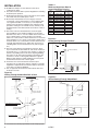
maintained. Units are designed for installation with the
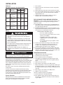
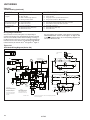
minimum clearances as shown in table 4.1.
Table 4.1 Clearances
Unit Side
Top and Bottom
Access Side
Non-Access Side
Rear
Vent Connector
Clearance To
Combustilble Materials
1"
18"
1"
18"
4"
Recommended
Service Clearance
1"
18"
1"
18"
4"
6. Do not install units in locations where gas ignition system is
exposed to water spray, rain, or dripping water.
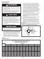
7. Mounting Height (measured from bottom of unit) at which
unit heaters are installed is critical. Refer to mounting height
information and heat throw data on page 16 of this manual.
The maximum mounting height for any unit is that height
above which the unit will not deliver heated air to the floor.
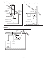
Combustion Air Requirements
The National Fuel Gas Code defines an “unconfined space” as
a space whose volume is greater than 50 cubic feet per 1,000
Btu/Hr input of the installed appliance(s). A confined space
is 50 cubic feet or less per 1,000 Btu/Hr input of the installed
appliance(s).
It is not recommended to install these unit heaters into residential
confined spaces. This recommendation is due to the concern
that at some point in time, the combustion air openings provided
by the installer may become blocked or eliminated by the owner,
either intentionally or unintentionally. Despite this commendation,
if these units are installed into a residential confined space, see
National Fuel Gas Code ANSI Z223.1 or CSA B149.1 Installation
Code, latest edition, for detailed combustion air provisions. These
requirements must be adheard to.
Units installed into confined spaces in industrial/commercial
installations, must be provided with two permanent openings,
one near the top of the confined space and one near the bottom
of the confined space. Each opening should have a free area of
not less than one square inch per 1,000 Btu/Hr of the total input
rating of all units in the confined space, freely communicating
with interior areas having, in turn, adequate infiltration from the
outside.
For further details on supplying combustion or to a confined (tightly
sealed) space or unconfined space, see the National Fuel Gas
Code ANSI Z223.1 or CSA B149.1 Installation Code, latest edition.
Turning The Unit 180°
CAUTION
1. Do not install units below 7' measured from the bottom of
the unit to the floor in commercial applications (unless
unit is properly guarded to provide user protection from
moving parts) and 5' measured from the bottom of the unit
to the floor in residential applications.
2. Be sure no obstructions block air intake and discharge
of unit heaters.
3. The minimum distance from combustible material is
based on the combustible material surface not
exceeding 160°F. Clearance from the top of the unit
may be requited to be greater than the minimum
specified if heat damage, other than fire, may occur to
materials above the unit heater at the temperature
described.
4. Allow 18" clearance at rear (or 6" beyond end of motor
at rear of unit, whichever is greater) and access side to
provide ample air for combustion and proper operation
of fan.
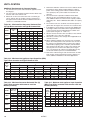
1. Be sure the means of suspension is adequate to support
the weight of the unit (see page 16 for unit weights).
2. For proper operation, the unit must be installed in a level
horizontal position.
3. Clearances to combustibles as previously specified must be
strictly maintained.
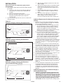
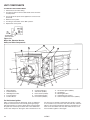
4. Mounting bracket installation:
Before lifting the heater for suspension, the mounting
brackets must be installed. Decide if the unit will be
installed as standard; that is with left-side controls when
looking at the front of the unit or with right-side controls.
For standard (left side)remove brackets from shipping
position and remove the (3) screws along the top edge of
both the front and back of unit. Align screw holes on
mounting bracket with holes along front and back top
edges. Secure (1) mounting bracket to front of unit with
retained screws. Secure the other mounting bracket to back
of unit in a similar way.
For right-hand, the mounting brackets are attached in a
similar manner after the unit is turned over.
5a. Suspension by screws/lag bolts:
Secure the mounting brackets to the ceiling joists or truss,
using 1/4" screws with 1/2" washers. These 1" - angle,
mounting brackets are slotted to accommodate joists on 16"
or 24" centerlines.
5b. Suspension by threaded rod:
This heater can also be hung utilizing the same mounting
brackets and threaded rod. Attach the threaded rod to the
unit mounting brackets, securing with a top and bottom nut.
Next, drill holes into a steel channel or angle iron at the
same centerline dimensions as those chosen for the heater
that is being installed. The steel channels or angle iron
pieces need to span and be fastened to appropriate
structural members. Cut the threaded rods to the preferred
length, push them through the holes in the steel channel or
angle iron and secure with washers and lock nuts, lock
washers and nuts, or a double nut arrangement like used on
the unit heater mounting brackets.
5c. Shelf mounted units:
The unit heater can also be installed on a shelf, if so
desired. The mounting brackets will need to be attached to
the heater the same manner as explained earlier, however,
to mount on a shelf the brackets must go on the bottom of
the heater. The brackets must be affixed to the shelf using
similar screws (1/4" screw with 1/2" washer) as overhead
joist or truss mounting. Be sure all clearance to combustible
requirements are met.
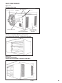
All units are produced at the factory with left-side controls, when
looking at the unit. If the installation requires that the controls be
on the right side, the unit heater can be “turned over”. In addition,
the following instructions must be followed:
• By turning the unit 180° from the way it was received from
the factory, the sides become opposite but the front and
back remain in the same relative position. The bottom panel
now becomes the top panel and vice-versa.
• Remove the access panel, turn it 180°, and re-attach it to
the unit. This is important so that all the information labels
can be read.
• Remove the spring loaded deflector blades, turn them over,
replace, and adjust so they are open and in a position to
4 direct the heated air down to the floor.
6-576.5