1
INSTALLATION
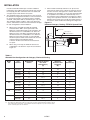
10. Do NOT use dampers or other devices in the vent or
combustion air pipes.
11. Precautions must be taken to prevent degradation of building
materials by flue products.
12. Single wall vent pipe must not pass through any unoccupied
attic, inside wall, concealed space, or floor.
13. All vertically vented heaters that are category I must be
connected to a factory built chimney or vent complying with
a recognized standard, or a masonry (or concrete) lined
chimney with a material acceptable to the authority having
jurisdiction. Venting into an unlined masonry chimney is not
permitted. Refer to the National Fuel Gas Code for common
venting.
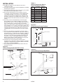
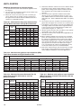
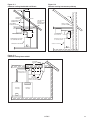
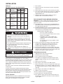
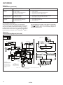
14. The outlet of the vent should extend as shown in Figure
6.3 and Table 6.1 if the following conditions are met: Vent
diameter is less than 12", vent is of double wall construction
and is a listed product, and the vent does not terminate
within 8’ of a vertical wall or similar obstruction. For vents that
have a diameter of 12" or larger, constructed of single wall, or
terminate within 8' of a vertical wall or similar obstruction, the
vent pipe shall extend at least 2' higher than any portion of
a building within a horizontal distance of 10’ (refer to Figure
6.2).
15. The vent system exhaust shall terminate at least 3’ above
any forced air inlet located within 10’, and at least 4’ below, 4’
horizontally from, or 1’ above any door, window, or gravity air
inlet into any building and 2’ from wall or adjoining building.
The bottom of the vent terminal shall be located above the
snow line or at least 1’ above grade; whichever is greater.
When located adjacent to public walkways the vent system
shall terminate not less than 7’ above grade.
16. A minimum of 4’ horizontal terminal clearance (6’ for
Canada) from gas and electric meters, regulators, and relief
equipment is required. The vent terminal shall not terminate
closer than 2’ to adjacent buildings.
17. Use an approved vent terminal to reduce down drafts and
moisture in the vent.
Table 6.1
Minimum Height from Roof to
Lowest Discharge Opening
Rise
X (in)
0-6
6-7
7-8
8-9
9-10
10-11
11-12
12-14
14-16
16-18
18-20
20-21
Roof Pitch
Flat to 6/12
6/12 to 7/12
7/12 to 8/12
8/12 to 9/12
9/12 to 10/12
10/12 to 11/12
11/12 to 12/12
12/12 to 14/12
14/12 to 16/12
16/12 to 18/12
18/12 to 20/12
20/12 to 21/12
➀ Size according to expected snow depth.
Figure 6.2
Vertical Venting Through Flat Roof
8' Min
Listed Terminal
2' Min
5' Min
4" Min
Drip Leg
Downward
Slope 1/4" towards drip leg.
Figure 6.1
Venting Through Combustible Wall or Roof
12" Min
Double Wall Vent Pipe ➀
Single Wall Vent Pipe
Listed
Terminal
Flashing
Min Height
H (ft) ➀
1.00
1.25
1.50
2.00
2.50
3.25
4.00
5.00
6.00
7.00
7.50
8.00
Listed
Terminal
Figure 6.3
Vertical Venting Through Sloped Roof
Listed
Terminal
Flashing
X
H
Listed
Thimble
Clearance Specified
by Type B Vent Mfg.
12
Roof Pitch is
x/12
Single
Wall
Double
Wall
Specified
Terminal
Single Wall Vent Pipe Terminating
with Double wall vent pipe. ➁
Clearance Specified
by Type B Vent Mfg.
4" Min
Single
Wall
Downward
Slope 1/4" towards drip leg.
Specified
Terminal
Single Wall Vent Pipe
Drip Leg
Listed
Thimble
➀
6
See Instructions for attaching single wall pipe to double wall pipe (page 6)
6-576.5
12" Min