1
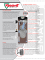
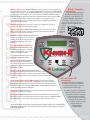
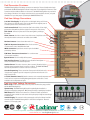
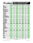
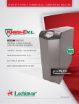
:::::::::::::::::::::::::::::::::::.
:::::::::::::::::::::::::.
The KNIGHT Heating Boiler is available in five models
from 80,000 to 285,000 Btu/Hr and has many
significant advantages over other condensing boilers
on the market today. KNIGHT Heating Boilers are
93% AFUE. When used in a low temperature
radiant heating application, efficiency is further
increased to 98%. This training document will
examine numerous features that give the KNIGHT
Heating Boiler its distinct competitive advantage.
The Jacket
The KNIGHT Heating Boiler is an appliance that compliments the house.
Refrigerators, stoves and dishwashers hold this distinction; and yes, even water
heaters are starting to. So why not your major heating appliance? Contractors today
take great pride in the appearance of piping and control systems used in residential
heating. Why shouldn’t the boiler be appealing as well? The KNIGHT Heating Boiler uses
a sculpted steel jacket which gives the contractor the ability to provide their customer
with a professional installation.
The jacket is not an integral part of creating the sealed combustion aspect of this appliance.
The KNIGHT Heating Boiler uses a direct air intake connection to the combustion air inlet fan.
This eliminates the need of a sealed outer jacket assembly and makes service to the boiler
much easier.
The rear of the jacket is also contractor friendly. The KNIGHT Heating Boiler provides 8 conduit
knockouts for field wiring connections and direct connection to the flue outlet of the appliance.
Illustration represents
KBN 285-500 models
Leveling legs are provided as standard equipment allowing for a professional, clean
installation on uneven floors. Panel removal for service and setup is made easier with the
KNIGHT Heating Boiler jacket. The top and front panels utilize snap pins that hold them
firmly in place. To access the interior, simply pull the panels off by hand.
The Combustion System
The KNIGHT Heating Boiler uses a sophisticated air/fuel delivery system
commonly referred to in the industry as a “Negative Regulation”
(Neg/Reg) arrangement. The speed of the fan constantly adjusts the
volume of fuel and air drawn into the burner. The faster the fan speed the
greater the negative pressure it creates; the greater the negative pressure,
the more fuel is drawn into the burner. The speed of the fan is directly
controlled by the SMART SYSTEM control. The SMART SYSTEM sends an
electrical signal to the fan enabling it to change speed. The electrical
signal is of a “Pulse Width Modulation” (PWM) type. In turn, the KNIGHT
Heating Boiler is capable of a 5:1 turndown firing rate.
The Neg/Reg combustion system also allows the KNIGHT Heating Boiler to
safely and reliably operate with supply gas pressure as low as 4" w.c. This
is a clear advantage when working with older homes in a retrofit application
or in the mountain areas of the United States. A Natural to LP gas
conversion kit is standard with all models.
The Ignition System
The KNIGHT Heating Boiler uses “direct spark ignition.” Direct spark ignition
utilizes two electrodes to create an ignition point. After a call for heat, the
SMART SYSTEM sends a high voltage electrical pulse to one of the
electrodes; the electrical pulse will then ground itself to the second electrode
creating a spark. The spark is responsible for igniting the air/fuel mixture.
A third electrode will then sense the flame through flame rectification. If
no flame is detected, the SMART SYSTEM will reset and attempt
ignition again for a total of 4 times . If no flame is sensed
after these attempts, the SMART
SYSTEM will lock out and display
the fault.
The Burner
The burner used in the KNIGHT
Heating Boiler is 411 stainless steel.
The burner is in a 360 degree
configuration and covers the
entire length of the primary heat
exchanger allowing for substantial
reduction in the overall size of
the appliance. Units that utilize
multiple burners are generally
much larger in size.
Illustration represents KBN 285
model combustion system
:::::::::::::::::::::::::::::::::::::::::::::: ::::::::::::::::
:::::::::::::::::::::::::::::::::::
::::::::::::::::::::::::::.
The SMART SYSTEM™ Control
SMART SYSTEM is truly the marquee item of this appliance.
Operation is simple to understand and doesn’t require special
training or certification. SMART SYSTEM is extremely user
friendly, and has the capability of diagnostics from the front
of the boiler or through simple PC or Pocket PC software.
The Heat Exchanger
The KNIGHT Heating Boiler’s heat exchanger is an advanced design.
Its construction is of 316L stainless steel tubes, headers and
casing. Stainless steel heat exchangers perform without constant
monitoring of the system pH. The tubes are welded into headers
eliminating the need for any gaskets or O-rings. The tubes are
oblong and formed utilizing an advanced hydro forming process.
Hydro forming uses pressurized water exceeding 10,000
psi to alter the shape of the stainless steel tube. This
easily creates the desired tube shape.
5:1 Burner Turn Down- SMART SYSTEM is
set to allow modulation of the burner down to
20% of maximum input. This range of
modulation allows the KNIGHT Heating Boiler to
match load requirements of the installation.
With this degree of load matching, energy
consumption is minimized under all conditions.
2 Line, 16 Character DisplayDiagnostics and set-up become much simpler.
The size and characteristics of the display allow
for actual words to be shown.
The heat exchanger appears to be one single
unit when it is in fact two heat exchangers in
one - the primary heat exchanger, which is
exposed to the burner flame; and a secondary heat
exchanger, which is only exposed to the flue gas.
The KNIGHT Heating Boiler is a condensing boiler that
allows condensation to occur only on the secondary
portion of the heat exchanger. This design allows for
entering water temperatures to be as low as 50°F
thus eliminating worry of damage to the primary
heat exchanger.
2 Levels of Password SecuritySMART SYSTEM allows for the programming of
a user password and an installer password.
This prevents any unauthorized tampering of
the appliance settings.
Product Service Indicator- The installer
can initiate this at the display. The indicator
can be programmed to display based on
number of cycles, hours of operation, or time
since last service.
The heat exchanger is ASME Section IV approved
and is marked with an “H” stamp indicating ASME
compliance. ASME approval for a pressure vessel
is important. ASME ensures the user and installer
of the highest quality in design and materials
possible for the heat exchanger.
Pump Relay w/ Freeze ProtectionSMART SYSTEM will monitor boiler water
temperature to ensure that if the temperature
falls below 40°F the pump will start forcing
circulation of the water. If the water
temperature continues to drop to 35°F the unit
will fire the burner until the water temperature
is raised to 40°F.
Effective January 2006 all ANSI Z21.13
certified boilers MUST carry an “H” stamp.
Venting
The KNIGHT Heating Boiler is certified as a Direct Vent
appliance. This approval allows the KNIGHT to use PVC
for exhaust venting and air intake. The KNIGHT Boiler
will allow for up to 100 feet of air intake pipe and 100 feet
of flue gas exhaust. Foam core PVC should never be
used for the flue gas exhaust. The KNIGHT Boiler should
be installed with schedule 40 PVC or CPVC. Common
industry codes and practice should always be
followed when installing and terminating the air
intake and flue gas exhaust. For difficult or
space restrictive installations, a concentric vent
termination is available as an option for the intake
and exhaust for models up to 285,000 Btu/hr.
A few of the basic functions of the
SMART SYSTEM CONTROL are:
Illustration represents
KBN 285 models
Low Water Flow Indication- SMART
SYSTEM monitors change in temperature
through the heat exchanger. If the difference is
large enough, the module will reduce the modulation rate
and shut the boiler down on temperature. However, this
should not be used as a safety device. A low water cut-off or
flow switch should be used for true low water protection.
Outdoor Reset- The KNIGHT Heating Boiler includes a
sensor to monitor outdoor air temperature. This is standard
and does not require the purchase of an option. The outdoor
sensor, when attached to the SMART SYSTEM, will allow the
boiler to operate on a reset schedule. The reset schedule
maintains the boiler water temperature to precisely meet the
load requirements of the installation.
.:::::::::::::::::::::::::::::::::::::::::
.::::::::::::::::::
.::::::::::::::::::::::::::::::::::::::::::::::
.::::::::::::::
“Built-In” Cascading
DHWP w/ Pump Control- SMART SYSTEM allows for direct connection to an indirect tank to meet
potable hot water requirements. The indirect tank thermostat will send a signal to the SMART SYSTEM
Sequencer
indicating a call for domestic hot water. SMART SYSTEM will then override the outdoor air reset and start
An internal sequencer is standard on
the DHWP pump to flow boiler water to the coil in the indirect tank. SMART SYSTEM drives both the
each KNIGHT and allows for lead/lag
firing rate and boiler discharge water temperature to the setting determined by the installer, allowing
sequencing of up to eight boilers. The
for a fast recovery of domestic hot water loads. The installer can also adjust the amount
lead/lag configuration rotates the lead
of time the boiler operates in an override setting, and the time the DHWP pump is allowed to
boiler after a 24 hour time period to ensure
operate after demand is satisfied.
equal runtime for all boilers. Since the
sequencer is built into the KNIGHT, there is no
Contacts on Any Failure- This allows for connection of an audible alarm in the event
need for an
of a boiler fault or will send an alarm signal to a BMS.
expensive
System Pump Control- SMART SYSTEM will supply power to, and operate, the system
third party
pump as needed. The installer can vary the amount of time the system pump is allowed to
sequencing
operate after a call for heat has been satisfied.
control.
Boiler Pump Control- SMART SYSTEM will start and
stop the boiler pump as needed and allows the
installer to set the amount of time the pump is
allowed to operate after the call for heat is
satisfied.
Inlet and Outlet Water Temperature
Sensors- SMART SYSTEM will display inlet
and outlet water temperatures, and allow the
installer to determine which sensor will be
used to control the boiler set point.
F or C- Allows the installer to set the unit to
display degrees Fahrenheit or Celsius.
Boiler Set Point- SMART SYSTEM allows
the boiler set point to be adjusted by the
user. The installer can program the minimum
and maximum set point parameters that the user
will be allowed to adjust.
Off Time Limiting- SMART SYSTEM allows the installer to
determine, in time, how long the unit must remain off prior to allowing
a new firing sequence to begin. The installer may also program the limit to
override if the water temperature drops significantly prior to the completion of the
limiting time.
Building Management System (BMS) Control- The installer can program the
control to accept a 0-10 VDC external signal. The BMS settings are: set point at low/high
input, low/high input range, BMS power setting at low/high range and the BMS differential
temperature setting. In order to program SMART SYSTEM to accept the BMS signal, setup must
be performed with the optional PC software kit.
PC and Pocket PC
Connection
The KNIGHT Heating Boiler is available with
PC software and hardware to troubleshoot
and program all functionality or Pocket PC
software with infrared technology.
Night Setback- SMART SYSTEM allows the installer to program a temperature setback for any time
in a 24 hour day, for each day of the week.
The software also allows for easy plotting
and trending of historical data. The data
can be used to determine many points
Service Mode- SMART SYSTEM includes a masked button that allows the boiler to be put into a
of reference including approximate
temporary service mode. This button allows manual control of the blower speed. SMART SYSTEM will
energy consumption. It is necessary
automatically return to normal operation after a timeout if no buttons have been pushed.
to purchase the PC software and
hardware to install and program
Building Management
The previous list gives a brief description of the functionality of the SMART SYSTEM control. The KNIGHT Heating
System features into
Boiler Installation and Operation or Service manual should be consulted for complete instruction to adjust any of
SMART SYSTEM.
these settings and features.
:::::::.
::::::::::::::::::::::::::::::::::::::::::::::::::::::
.::::::::::::::::::::::::::::::::::::::::::::::::::::::::
Field Connection Provisions
The KNIGHT Heating Boiler’s field wiring connections are extensive. The user friendly terminal strip
provided with all KNIGHT Heating Boilers allows for 28 points of low voltage field connections. These
connections may be additional safeties or accessories. The KNIGHT Heating Boiler also provides for
4 line voltage connections. Line voltage connections are for power supplied to the unit, and power
distribution for up to three pumps operated by the SMART SYSTEM Control.
Field Low Voltage Connections
A 24 VAC Pilot Supply- This will provide a 24 VAC signal during a call for heat.
This connection is commonly used to close a relay which in turn supplies power to
an auxiliary device such as a mechanical room fan.
Gas Pressure Switch- These connections allow for the addition of low or high
gas pressure safety switches, which are required in many areas of the country.
Flow Switch- Connection points used for flow sensing with a paddle type
flow switch.
Alarm Contacts- Provides a contact closure in the event of any failure to the unit.
Generally this would be connected to an audible alarm or BMS.
Runtime Contacts- Contact closure when unit is on.
R/W Tank Aquastat Connection- Allows for the connection
of a thermostat to control the DHW indirect tank.
LWCO Connection- Specialized connection point for the LWCO
provided by Lochinvar.
R/W Room Thermostat Connection- For room thermostat
or zone control installation.
System Sensor- Used for multiple boiler systems.
Tank/Auxiliary Sensor- The DHW tank sensor allows the Smart System
control to maintain the stored water temperature.
Outdoor Sensor- The outdoor air sensor, when connected, allows the boiler to
maintain a water temperature based on outdoor conditions. The SMART SYSTEM will
automatically detect when an outdoor air sensor is connected.
Cascade Sequencing These connections allow up to 8 individual units to be
“daisy chained” together to provide for sequenced operation under the control of a
single “leader” boiler.
0-10 VDC External Control- Allows the contractor to tie an external temperature
control such as a sequencer or Building Management System to the boiler to control
modulation rate or temperature set point.
Field Line High Voltage Connections
Boiler Pump- This connection must be used to provide 120 VAC to the pump provided
with the KNIGHT Heating Boiler.
System Pump- The KNIGHT Heating Boiler performs optimally when installed in a
primary/secondary piping arrangement. With primary/secondary, a system pump is required.
DHW Pump- When installed and connected to a domestic hot water prioritization
arrangement, these contacts are used to start and stop the pump moving hot water through
an indirect tank.
120 VAC Supply- This connection is the power supply to the boiler. Always install the
electrical supply to the KNIGHT Heating Boiler in a hard wired configuration. Never use
extension cords to supply power.
Lochinvar Corporation • 300 Maddox Simpson Pkwy • Lebanon, TN 37090 • 615-889-8900 / Fax: 615-547-1000
www.Lochinvar.com • www.knightheatingboiler.com
KBI-05
(Reprint KBI-04 5/07)
2/08-Printed in U.S.A.