1
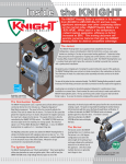
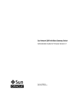
SOLARLOGIC
User’s Manual for
SLIC Generation II
Fred Milder and Bristol Stickney
27 June 2012
User’s manual for the SolarLogic Integrated Control (SLIC), a complete control system for ‘Solar
Combisystems’ with multiple heat sources and multiple heat loads.
-1-
© 2012 SolarLogic, LLC
USER’S MANUAL FOR THE SOLARLOGIC SLIC GEN II
TABLE OF CONTENTS
User’s Instructions - SolarLogic SLIC Gen II with VSLIC Software
Figure 1: SLIC Gen II Control Box.
5
5
Manual Heating Control Using Room Thermostats
6
Figure 2: SolarLogic Room Thermostat.
6
Components Required for Network Access and Full Control
6
The SLIC Gen II Boots Up Running
7
VSLIC Software for Full Access and Adjustment
7
Install and Run the VSLIC Software
8
Login, Connect, Adjust and Logout using VSLIC Software
8
Figure 4: VSLIC Screen Display Sequence During Login
9
Adjusting a SLIC using the VSLIC Software - ‘Adjust/Save’ Button, ‘Revert’ Button
10
Time-Out Fail-Safe Feature
10
VSLIC Controls are Grouped Together by Tabs
10
‘Dashboard’ Tab
11
Room Thermostat Dashboard Display
11
Domestic Hot Water (DHW) Dashboard Display
11
Solar Available Dashboard Display
11
Dashboard Display Indicator Lights and Whole House Mode
11
Figure 4: VSLIC ‘Dashboard’ Tab Screen Display
12
‘Detail’ Tab (Detailed System Status)
13
Figure 5: VSLIC ‘Detail’ Tab Screen Display
13
-2-
© 2012 SolarLogic, LLC
‘History’ Tab
13
Energy Usage
13
Figure 6: VSLIC ‘Energy Usage’ Tab Screen Display
Parameter Profiles
14
14
Figure 7: VSLIC ‘Parameter Profiles’ Tab Screen Display
Log Access
15
15
Figure 8: VSLIC ‘Log Access’ Tab Screen Display
16
‘Zones’ Tab
16
Figure 8: VSLIC ‘Indoor Zones’ Tab Screen Display
16
Indoor Zones
17
Domestic Hot Water (DHW) Minimum
20
Figure 11: VSLIC ‘DHW Minimum’ Tab Screen Display
Setback Groups
20
20
Figure 12: VSLIC ‘Setback Groups’ Tab Screen Display
DHW Recirculator
21
21
Figure 13: VSLIC ‘DHW Recirculator Tab’ Screen Display
22
‘System’ Tab
22
What to do if there is a problem.
23
Technical Appendices
24
CONTROL SETTINGS AND DISPLAYS – SUMMARY TABLES
25
DASHBOARD – Described in the User’s Manual Main Section.
25
DETAIL – Described in the User’s Manual Main Section.
25
ENERGY USAGE
25
PARAMETER PROFILES
26
-3-
© 2012 SolarLogic, LLC
LOG ACCESS
27
INDOOR ZONES
28
POOL/SPA
29
ICE MELT ZONES
30
DHW MININUM
31
SETBACK GROUPS
32
DHW RECIRCULATOR
33
SOLAR AVAILABLE
34
DOMESTIC HOT WATER
36
STORAGE OUT (1)
38
STORAGE OUT (2)
39
PANELS
40
COMMUNICATION
41
PIPING DIAGRAM – TYPICAL PIPING CONFIGURATION BLOCK DIAGRAM
42
CONNECTOR BOARDS WIRING – SUMMARY TABLES
43
INPUT BOARD
43
INPUT DIAGRAM
44
INPUT LIST
45
OUTPUT BOARD
47
OUTPUT DIAGRAM
48
OUTPUT LIST
49
Glossary of Terms
50
-4-
© 2012 SolarLogic, LLC
USER’S INSTRUCTIONS - SOLARLOGIC SLIC GEN II WITH VSLIC SOFTWARE
The SLIC (SolarLogic Integrated Controller) is a combination hardware/software system controller typically
installed to control “Solar Combisystems”. These are heating systems that have several different heat
sources that all provide heat to many different end-uses. The SLIC replaces all conventional controls, adds
intelligent logic, and provides a host of internet-delivered bene?ts such as remote monitoring,
diagnostics, data logging, and remote system operation over the internet. The SLIC uses a ?le with
instructions provided by the SolarLogic Assisted Solar Heating Design (SLASH-D) software for information
about the heating system, so it starts-up knowing exactly how to operate the system, eliminating the
need for programming and lengthy set-up procedures.
FIGURE 1: SLIC GEN II Control Box.
The SolarLogic Integrated Control (SLIC) is typically installed to control all the heating equipment in a solar
heated home.
-5-
© 2012 SolarLogic, LLC
MANUAL HEATING CONTROL USING ROOM THERMOSTATS
The SLIC Gen II system can be operated by the occupants of the building without computer access, using
only the room thermostats provided by SolarLogic. Any occupant can turn the knob on thermostat up or
down to increase or decrease the target temperature in that heating zone. Also, the switch at the bottom
of the thermostat can be set by any occupant to Solar Only, Normal or Auxiliary mode.
Solar mode prevents that zone from being heated with backup fuel unless it is in danger of freezing
(below 45F), and uses only solar heat to try to meet the target temperature indicated by the knob.
Normal mode allows the solar heat to be used to meet (or exceed by a few degrees) the target
temperature set by the knob, and uses backup fuel only to meet the minimum target temperature when
solar heat is not available. Aux mode (auxiliary heat) forces the backup heat to maintain the target
temperature very closely in that zone without regard to the availability of solar heat (but still allows the
use of solar heat when available).
FIGURE 2: SOLARLOGIC ROOM THERMOSTAT.
COMPONENTS REQUIRED FOR NETWORK ACCESS AND FULL CONTROL
To gain full access and control over the SLIC Gen II heating system control functions, the following steps
must have been completed by the installer:
1. A SLIC Gen II control system is installed and properly connected to all the heating system
components (see Figure 1);
2. A local network router is properly connected to the SLIC control box via a hardwire connection
(Figure 3); and
3. A computer running VSLIC software (supplied with the SLIC installation – see below) is also
connected to the network or to the internet.
-6-
© 2012 SolarLogic, LLC
Figure 3: Diagram of Network Connectivity. The complete heating system installation
includes a SLIC control box with a hardwire network (LAN) connection and a computer on the same LAN
with VSLIC software installed on the computer. The minimum requirement for the LAN is a router that
assigns DHCP IP addresses. To have remote access to the SLIC from outside the LAN, the LAN must be
connected to the internet.
THE SLIC GEN II BOOTS UP RUNNING
When the SLIC control system is properly installed and powered on, it boots up like any computer. It
‘wakes up’ running the heating system for the house and begins normal operation by reloading all the
required data and settings from permanent files. This happens automatically any time power is restored
for any reason (following a power failure, maintenance shutdown, etc.). Thus, any setting that has been
saved after it was last adjusted is reloaded upon reboot. When power is restored and boot-up is
complete, all room thermostats, pumps, zone valves and sensors become fully operational, even without
any computer or network connection. Note, this means that although a LAN and/or internet connection is
necessary for full monitoring and adjusting parts of the SLIC system, once it is set up, no LAN or internet is
required for proper functioning of the heating system.
VSLIC SOFTWARE FOR FULL ACCESS AND ADJUSTMENT
The SLIC control box does not contain any user adjustments or displays. This is because it is designed for
access using a computer over a network. Each SLIC is connected to a Local Area Network (LAN) and can
be monitored and adjusted by VSLIC software (see below) from any computer on that network. If the LAN
is connected to the internet, the same VSLIC software may be used for remote operation over the
internet as well.
The software program called Virtual SLIC.exe (aka. VSLIC) is provided by SolarLogic and presently runs only
on Windows based PCs. (Future updates will be compiled for other operating systems.) This software can
be installed on multiple computers at any network location (local or remote) and used to monitor and
adjust the SLIC system from different locations. Typically the installer, several occupants and SolarLogic
may be granted access from different network computers. Access to an installed SLIC is controlled by a
combination of the VSLIC software, the SolarLogic central server and the SLIC itself through user IDs and
passwords. More than one user can be logged on to a SLIC at the same time. This feature makes it
possible for the system owner and the installer to collaborate in adjusting a system or diagnosing issues
-7-
© 2012 SolarLogic, LLC
without either being on site. It also facilitates communication with SolarLogic technical support and to
perform joint work and to diagnose and fix problems on any system.
INSTALL AND RUN THE VSLIC SOFTWARE
The software is provided as an install program in a Windows file folder. To install it, copy (drag) the entire
installation file folder onto your computer and then run the ‘setup’ file within the file folder. Once the
installation is complete, the installation file folder can be deleted to save space on your hard drive if you
so choose, but will be needed if you want to reinstall the VSLIC at a later time. If you have been provided
the VSLIC installer on a portable device, such as a USB drive, the installer can also be run from that
medium directly. The setup routine creates a desktop icon and two working folders on your computer:
C:\SLIC for data buffering and storage, and C:\program files\SolarLogic for the executable program. (On
Windows systems later than XP, the folder ‘program files’ may have a different name such as ‘program
files x86’.) The main program is named ‘Virtual SLIC.exe’ and to run the VSLIC software, double click the
desktop icon after it has been installed. A Login Window will appear as seen at the top of Figure 4.
LOGIN, CONNECT, ADJUST AND LOGOUT USING VSLIC SOFTWARE
Connection to a SLIC system is accomplished with the VSLIC software, following Steps 1 through 10 as
shown in Figure 4:
1.
2.
3.
4.
Startup ‘Virtual SLIC.exe’ and wait for blank Login screen to appear (on the Communications tab).
Type in a previously created Username in the Username box.
Tab down to the Password Box and type in the corresponding Password. Press Enter.
Wait for the program to search for SLIC control systems and display their Names and ID numbers.
The VSLIC searches the SolarLogic central server as well as your local network. The results from
the server appear quickly unless there is a problem with your internet connection. For SLICs on
your local network, the search can take as much as a minute.
5. Choose the SLIC you want – Click on its name and ID number (it will then be highlighted).
6. Click on the ‘Local/Remote’ toggle button to change to the type of network connection you
prefer. If you only have one connection choice for the desired SLIC, the button will be greyed out
and inoperable but will show you the connection mode. In most situations, if a local connection
is available, it is preferred, as the interaction with the SLIC will be faster.
7. Click on the ‘OK’ button to connect.
8. Wait for the VSLIC Dashboard to appear for the chosen SLIC over the chosen network connection.
9. Use the Tabs at the top of the screen to move between other screen displays and controls.
10. To end your connection to a SLIC system, press the ‘Logout’ button (top right on screen). When
the login screen appears in full color again, you may close the program using the top right “X”
button.
(Although not recommended, the program can also be ended without logging out by using the ‘X’ button
at the top right at any time; and, as with any program on a Windows machine, if closing the program is
problematic for some reason, pressing the ‘Control-Alt-Delete’ keys will take you to the ‘Task Manager’
where any program can be forced to quit.)
At any time while interacting with a SLIC, if adjustable controls and buttons appear in grey (‘greyed out’),
they are not available to the current user either because they do not exist in the plumbing configuration
being accessed, or the current user does not have the password authority to access these features. The
Tabs and control functions mentioned in ‘Step 9’ are explained in more detail below.
-8-
© 2012 SolarLogic, LLC
FIGURE 4: VSLIC SCREEN DISPLAY SEQUENCE DURING LOGIN
-9-
© 2012 SolarLogic, LLC
ADJUSTING A SLIC USING THE VSLIC SOFTWARE - ‘ADJUST/SAVE’ BUTTON, ‘REVERT’ BUTTON
The VSLIC software is configured to prevent accidental adjustment of heating system parameter values, so
when a user wants to change the heating system settings, the ‘Adjust’ button must be pressed first. The
button label changes to ‘Save’ and changes from green to red. A new value can now be typed into any
setting that is not “greyed out”. Typically, the settable controls appear as numbers on a white background
with increment/decrement buttons next to the control. The notable exceptions are the pull down
controls and some of the sliders that go from greyed out to full color but do not turn white. Whenever a
control parameter is changed, it turns yellow and the tab name gets an asterisk. If the tab you are
working on is a sub-tab, its “parent” tab also gets an asterisk. In this way, you can relocate and know
which parameters you are in the process of changing at any time during an adjustment procedure. A
discussion of the various parameters of interest to the system owner
After you have made changes to as many parameters as you wish, click the ‘Save’ button. A dialog box
appears, allowing a review all of the changes. Accept them by ‘Sending’ the command, or return to the
adjustment procedure by ‘Canceling’. No changes are made to the actual SLIC that you are logged onto
until the command has been sent. Once Send has been selected in the confirm dialog box, changes can
only be undone by readjusting them back to their old values. However, if during your adjustment
procedure you wish to cancel all of the adjustments in process before you get to the confirming dialog
box, you can click on the ‘Revert’ button. This will undo all of the changes made from the time you
activated the ‘Adjust’.
TIME-OUT FAIL-SAFE FEATURE
The VSLIC software is also designed to prevent unexpected or unwanted heating system performance due
to human neglect or inattention after the adjust button has been pressed. Thus, if the operator is called
away or forgets that the VSLIC is running with the adjust button pressed, the VSLIC will reset the adjust
button to “off” and revert all parameters to their last saved values after a period of approximately 15
minutes. (The SLIC controller which the VSLIC is logged onto continues normal heating system operation
using the last settings that were saved normally by the user because it has not received a command to
change them.)
VSLIC CONTROLS ARE GROUPED TOGETHER BY TABS
The VSLIC software displays information in groups that are accessible by clicking the Tabs at the top of the
screen. There are six main categories and these Tabs are labeled:
• Dashboard,
• Detail,
• History,
• Zones,
• System, and
• Communication.
(There are also a ‘Diagnostics’ button and a ‘Reboot’ button that allow a qualified Installer to access
controls for maintenance and troubleshooting and to reboot a SLIC remotely. Owners do not have access
to these functions.)
- 10 -
© 2012 SolarLogic, LLC
In this section we will only be describing the information and adjustable parameters on each screen that
are useful to the homeowner. There are system parameters on other and several screens discussed here
that are available only to the installer and SolarLogic, and used only when fine tuning of the system to
maximize your energy savings or to better match the system performance to the living patterns in the
building. Information on those parameters is presented in the Technical Appendices.
‘DASHBOARD’ TAB
The System Dashboard displays a summary of the entire heating system and a sample can be seen in
Figure 4. For each major system component a red thermometer and a blue indicator are displayed, as
well as a green light indicating if that component is active. The red thermometer shows the current
temperature of that component and the blue indicator shows the target temperature. (The colors may
vary in your system based on your computer’s color scheme.)
ROOM THERMOSTAT DASHBOARD DISPLAY
For all the room zone heat loads and the pool and spa heat loads, the setting indicator shows the Comfort
Target (CT). This is the temperature that the system is targeting for that zone. Generally, if there is solar
heat available, the system will heat the zone slightly above the CT. If there is no solar heat available, the
system will let the zone cool off slightly below the CT before it turns on your auxiliary (fuel-based) heat
source. This spread, from slightly warmer to slightly cooler than the CT is called the Comfort Band (CB).
The CT is adjusted at the physical thermostat. The CB is adjusted via the VSLIC on the ‘Zones’ tab, ‘Indoor
Zones’ sub-tab (see later section).
DOMESTIC HOT WATER (DHW) DASHBOARD DISPLAY
For Domestic Hot Water (DHW), the thermometer shows the DHW temperature at the top of the water
tank and the setting indicator shows the minimum temperature allowed before the system turns on the
auxiliary heat source to generate hot water. The DHW minimum setting is adjusted via the VSLIC on the
‘Zones’ tab, ‘DHW Minimum sub-tab (see later section).
SOLAR AVAILABLE DASHBOARD DISPLAY
For Solar Available, the thermometer shows the temperature of the fluid as it arrives in the house from
the solar panels (Solar Source) and the setting indicator shows the temperature at which the system
considers that solar heat is available to be used by for zone space heating. The adjustment of the Solar
Available setting is for installers and SolarLogic only.
DASHBOARD DISPLAY INDICATOR LIGHTS AND WHOLE HOUSE MODE
The dashboard lights show if there is heat being delivered to any zone, (including ice melt zones, pools or
spas if present in the system), whether the boiler is on for auxiliary heat generation, if there is heat
dissipation active (to protect the panels from overheating).
The Whole House Mode (WHM) of the system is displayed and selected on the Dashboard. The WHM is
set via the VSLIC and functions in the same manner as the three-position switch at the bottom of each
thermostat. The WHM on the Dashboard has five modes altogether: Solar, Normal and Auxiliary, similar
to the thermostat switches, plus Off and Cooling. Off turns off all space heating zones but does not turn
off the DHW heating or the pool and spa heating. To turn off a pool or spa, merely turn the physical
thermostat all the way to the left. Cooling mode functions the same as Off mode but adds Night Sky
Radiant Cooling (NSRC) for radiant in-masonry zones. See later sections for NSRC. Any WHM mode other
- 11 -
© 2012 SolarLogic, LLC
than Normal overrides the individual thermostat switch settings, with the exception of the pool and spa
noted above.
FIGURE 4: VSLIC ‘DASHBOARD’ TAB SCREEN DISPLAY
- 12 -
© 2012 SolarLogic, LLC
‘DETAIL’ TAB (DETAILED SYSTEM STATUS)
The system status Detail tab is seen in Figure 5. It shows the on/off status of every heat load, heat source,
valve and pump in the entire system, all system level temperatures (i.e., all temperatures except the
individual zone. temperatures) and additional sensor values if present in the system (AC current draw,
pressure, flow, pH). The labels for most items are self-explanatory. There are no adjustable parameters
on the Detail tab.
FIGURE 5: VSLIC ‘DETAIL’ TAB SCREEN DISPLAY
‘HISTORY’ TAB
The History Tab contains three sub-tabs: Energy Usage, Parameter Profiles and Log Access. These
categories are all related to data records and settings that can be saved by the VSLIC program. There are
no adjustable parameters on the History tab.
ENERGY USAGE
Summary energy production and usage numbers are calculated and displayed on this sub-tab if the
system has the optional energy monitoring package installed. There are three display formats to choose
- 13 -
© 2012 SolarLogic, LLC
from: 1) Day by hour. This selection displays either today’s or today’s and yesterday’s energy numbers in
an hour by hour format. 2) Year by month. This selection displays one or two years’ energy numbers in a
month by month format. Any years for which the SLIC has been in operation can be chosen. 3) 15-day
Spread. This selection displays daily energy numbers for a 15-day time span centered on a chosen date
within the past year in a day by day format.
For any display format, there are seven values which can be displayed as line graphs:
1. Solar In – the total solar heat delivered into the house for DHW, Storage Tank and Central Heat;
2. Outdoor BTUs – the total BTUs delivered from the boiler plus the Storage Tank to outdoor
heating zones (but not including the heat delivered directly from the collectors to the outdoor
zones);
3. Tank & DHW Cooling – the total BTUs removed from the DHW and Storage Tank for collector
overheat buffering;
4. Zone Cooling – the total BTUs removed from the house zones by NSRC;
5. Boiler Output – the total BTUs output by the boiler for making DHW and heating zones (indoor
and outdoor);
6. DHW Heating – the net total BTUs (solar plus boiler) delivered to make DHW. Note that this
result automatically subtracts the BTUs removed from the DHW tank for the collector overheat
buffering noted above (item 3);
7. Central Heating – the total BTUs (solar plus boiler) delivered to indoor space heating zones
during the heating seasons.
Note: For any particular system, due to plumbing variations, there may be some energy numbers
that are either only rough approximations or not applicable. Consult with SolarLogic to find out
which energy measurements are valid for your system.
FIGURE 6: VSLIC ‘ENERGY USAGE’ TAB SCREEN DISPLAY
PARAMETER PROFILES
All the settings in the SLIC can be saved together as a group called a “profile”. Profiles can be selected
and reinstalled without manually entering each setting individually. Double click on a profile to reload it.
- 14 -
© 2012 SolarLogic, LLC
Profile names (user defined) should use only standard alphanumeric characters (A-Z, a-z, 0-9 and spaces).
Profiles are most often used in systems where there are seasonally adjusted settings. After a system has
been adjusted for a particular season and is running both in an energy efficient manner and in accordance
with the owner’s preferences, it should be saved as a profile. In following years at that season, reload the
saved profile to put the SLIC into the same operating condition. Saving and naming Profiles are selfexplanatory via the buttons on the Parameter Profiles sub-tab.
FIGURE 7: VSLIC ‘PARAMETER PROFILES’ TAB SCREEN DISPLAY
LOG ACCESS
The log files in the SLIC are like the “black box” on an airplane, recording every aspect of the heating
system performance for later inspection or analysis. The SLIC records every detail of the system status
every 5 minutes in files kept on the SLIC and also uploaded to the SolarLogic Central Server. The user is
shown a list of the log files available for viewing and downloading. There is a new file started three times
each month, on the 1st, 11th, and 21st of each month. The log files are named according to the date they
are started in year-month-day format. Log files can be retrieved from either the SLIC or from the central
server by double clicking on the log file name. The files are saved on the local computer (the one running
the VSLIC) in a spreadsheet format. The spreadsheet can later be used to draw graphs or do calculations
when inspecting the heating system performance.
- 15 -
© 2012 SolarLogic, LLC
FIGURE 8: VSLIC ‘LOG ACCESS’ TAB SCREEN DISPLAY
‘ZONES’ TAB
The Zones Tab is where the detailed settings are located for all the heating loads, which are grouped into
six sub-tabs;
• Indoor Zones,
• Pool/Spa,
• Ice Melt Zones,
• DHW Minimum,
• Setback Groups, and
• DHW Recirculator.
FIGURE 8: VSLIC ‘INDOOR ZONES’ TAB SCREEN DISPLAY
- 16 -
© 2012 SolarLogic, LLC
INDOOR Z ONES
R OOM T HERMOSTAT C ONTROL – 2-S TAGE H EATING
Each Room Heating Zone screen shows the detail status and settings of its zone. The current zone
displayed is selected in the list box on the right side of this screen. The overall settings are a result of the
settings of the physical thermostat in the zone and the software settings on this screen and on the
Setback Groups tab. The operation of the SLIC zone heating system is referred to as 2-stage heating: solar
heat and auxiliary heat. Two-stage heating is done to maximize the energy savings provided by your
SolarLogic heating system. The two main control parameters of 2-stage heating are the Comfort Target
(CT) and the Comfort Band (CB). The CT is set at the physical thermostat in the zone – what one normally
thinks of as the thermostat setting. The CB is set in software from this screen. In general, the
homeowner will not be adjusting the CB, and will use the CT setting on the physical thermostat just like
any normal thermostat. On the thermometer on this screen, the current zone temperature and the CT
are indicated. The Comfort Band setting appears in a box to the left of the thermometer.
H OW THE C OMFORT T ARGET AND C OMFORT B AND C ONTROL 2-S TAGE H EATING
The Comfort Target is just that – it is a target for the heating system. You should not expect the
temperature in the zone to spend most of its time at the CT. The Comfort Band in combination with the
CT quantifies where you should generally find the zone temperature. When solar heat is available, the
system will continue to put heat into the zone until it is approximately at the temperature of CT + ½ CB. If
there is no solar heat available, the system will let the zone cool off until it is approximately at CT – ½ CB
before it turns on your auxiliary heat source. For example, if the CT is 68F and the CB is 6F, the system will
put solar heat into the zone until it goes slightly above 71F; and it will not turn on the auxiliary heat until
the zone is below 65F.
On the screen display, the light and dark green regions on the thermometer are where only solar heat is
active, the top of the dark region showing where the solar heat will turn off. The dark red region is where
the auxiliary heat will turn on, and it will stay on until the zone temperature is above the pink region.
Additionally for further energy savings, if solar heat is available to heat the zone, the SLIC system can be
set to not turn on auxiliary heat even if the zone is in the red region. This parameter (found on the
System tab, Solar Available sub-tab) is set by your installer and the default is to NOT allow the auxiliary
heat to come on regardless of the temperature in the room if solar heat is available.
For further energy savings and comfort, the default settings of the SLIC give priority solar heat to any zone
that is in the red region. Example: If zone 2 is in the red region and zone 1 is in the green region and solar
heat is available, the SLIC will preferentially send solar heat to zone 2 and turn off heat delivery to zone 1
until zone 2 comes out of the pink region.
T HERMOSTAT M ODES
Lastly on this screen, the operating mode of the zone is displayed. The available modes are: Normal
Heating, Solar Only, Auxiliary, Off and Cooling. The mode being used is normally set by the three position
switch at the bottom of the zone thermostat for Normal, Solar Only and Auxiliary. However, via the VSLIC
software a Whole House Mode (WHM) can also be set. If the WHM is set to any mode other than Normal
Heating, it overrides the local switch settings of all of the physical zone thermostats. Off and Cooling can
only be set as a Whole House Mode.
- 17 -
© 2012 SolarLogic, LLC
Room Heat Operating Modes:
NORMAL HEAT – Operation is as described above in the discussion of 2-stage heating.
SOLAR ONLY – Turning on of the auxiliary heat is prevented unless there is risk of freezing in the
zone (i.e., the zone temperature drops below 45F). This mode is particularly useful to save fuel
costs during the Fall and Spring or for a room rarely used in the winter. The mode is also useful
for a vacation home not occupied for extended periods in the winter.
AUXILIARY – Affectionately called “grandmother mode,” this mode turns on the auxiliary heat
when the room drops only slightly below the CT. It is for when you want a room to always stay
near or above the CT, as when granny visits and complains about keeping the house so cold just
to save a little energy. This mode is also useful for rewarming the house more quickly in
preparation for occupancy if the house has been in Solar Only mode. Note however that this
mode will burn fuel to achieve that result except when there is solar heat available during the
daytime.
OFF – Turns off all space heating zones but does not turn off the DHW heating or the pool and spa
heating. The Off Mode is set by the Whole House Mode on the Dashboard tab.
COOLING – Your SolarLogic heating system provides Night Sky Radiant Cooling (NSRC, sometimes
referred to just as “radiant cooling”) during the summer months for almost no additional cost.
Cooling Mode is a Whole House Mode where heat is taken out of the floors at night and sent off
into the sky via your collectors or special radiant cooling panels. In Cooling Mode during the day,
solar and backup heat is delivered normally to the DHW, spa and pool heat loads. An effective
NSRC system can lower the masonry floor temperature by several degrees overnight and save air
conditioning costs or provide cooling if there is no air conditioning. The NSRC function is
controlled by the Whole House Mode and the local thermostats in combination. First, the WHM
must be set to Cooling; second, only those zones with their physical thermostat switches set to
Solar will receive NSRC. This is so you can prioritize where the radiant cooling should be
concentrated in the building. In order to have a room accept radiant cooling, the thermostat
switch must be in Solar mode.
IN COOLING MODE THE THERMOSTAT COLORING LOOKS UPSIDE DOWN FROM THE HEATING MODES. THE COOLING
TURNS ON IN THE LIGHT GREEN AREA ANY TIME THE COLLECTORS ARE COOL ENOUGH, AND TURNS OFF WHEN THE
ROOM IS COOLED BELOW THE DARK GREEN AREA.
The parameters work similarly to the Normal heating
mode: The cooling is turned on when the room is above CT + ½ CB (if the panels are cool enough
at night) and turned off when the room is below the on setpoint minus the Cooling Hysteresis
(Off Setpoint = CT + ½ CB – Cooling Hysteresis). The On and Off Setpoints are displayed on the
zone screen. In cooling mode, since there is no auxiliary cooling connected to the SLIC, the
Auxiliary parameters are irrelevant and non-functional.
- 18 -
© 2012 SolarLogic, LLC
SPA AND POOL ZONES
The spa and pool zones are similar to a room heating zone with a few important exceptions. Most
importantly, spa and pool heating are active regardless of the Whole House Mode. If you want to turn
spa or pool heating off, turn the thermostat all the way to its lowest setting (to the left).
FIGURE 9: VSLIC ‘SPA AND POOL ZONES’ TAB SCREEN DISPLAY
The other important differences in the spa and pool zones are done to prevent the pool from getting too
warm for comfort or the spa getting too hot for safety. First, the system will not heat the spa above
approximately 106F regardless of any settings. Second, the temperature at which the auxiliary heat is
activated to heat the pool or spa is equal to CT–CB. Third, the system will only allow the pool or spa to get
approximately 1 degree hotter than the comfort target, CT. Thus you should set the CT for the pool or spa
near the top of the range of temperatures that you would like to use the water feature at.
The Solar Only mode and the Auxiliary mode work similar to the room zones. If you want to save energy
and only use free solar heat, set the thermostat to Solar Only mode; if you want the water feature to
warm up to near the CT quickly by using back-up fuel if necessary, set the thermostat to Auxiliary mode.
Note however that Auxiliary mode can use a lot of backup fuel for heating a pool since the volume of
water that must be heated is much larger than for a spa. Neither the spa nor pool participates in Night
Sky Radiant Cooling.
ICE MELT ZONES
Ice Melt Zones have two activation methods: a physical timer or other external switch installed for the
zone, and a software timer. The Ice Melt Zone screens show which of the activation methods, if any, are
currently active. With the VSLIC, you can start up (or stop) an ice melt zone and also set the length of
- 19 -
© 2012 SolarLogic, LLC
time the zone is active for the software timer. With an external switch (normally open; close to activate),
an ice melt zone is active for as long as the switch is closed. Whenever an Ice Melt Zone is active, it will
use both solar and auxiliary heat to melt the snow and ice. Ice Melt Zones are also used for heat
Dissipation during the summer.
FIGURE 10: VSLIC ‘ICE MELT ZONES’ TAB SCREEN DISPLAY
DOMESTIC HOT WATER (DHW) MINIMUM
The Domestic Hot Water Minimum tab shows the temperature at which the system will turn on the
auxiliary heat source in order to make hot water. This is the same setting that is shown on the Dashboard
DHW thermometer and is commonly referred to as the “shower temperature.”
FIGURE 11: VSLIC ‘DHW MINIMUM’ TAB SCREEN DISPLAY
SETBACK GROUPS
This set of controls allows the user to program the room thermostats for lower settings (setback) at
certain times of the day to save energy. Multiple room thermostats may be grouped together to use the
- 20 -
© 2012 SolarLogic, LLC
same settings so that each thermostat does not need individual programming. There are three group
settings available for any thermostat: Group A, Group B and No Setback, and any number of thermostats
may be in a group. When the Group is selected in the upper right list box on the Setback Groups tab, the
zones belonging to that Group are highlighted in the Included Zones list box below it. The assignment of a
particular zone to a chosen Group is done on thermostat display for that zone on the Indoor Zones tab.
FIGURE 12: VSLIC ‘SETBACK GROUPS’ TAB SCREEN DISPLAY
The setbacks function as an offset to the physical thermostat settings, so that each room is still always
under the overall control of the physical thermostat. This allows the user to have on-demand and final
control over zone/room temperatures. Looking at the figure above as an example, Group A is chosen and
indicates that the Bar, the Kitchen and the Theater are all included in Group A. The offsets for Group A
are: +5 from 6:45 AM to 12:30 PM; –1 from 12:30 PM to 4:30 PM; +1 from 4:30 PM to 10:30 PM; and –4
from 10:30 PM to 6:45 AM (next day). Thus for example, if the Bar physical thermostat is set for 70F, the
Comfort Target in effect for the Bar will be 75F, 69F, 71F and 66F for the respective time blocks. If the
VSLIC is in adjust mode, settings of both the time blocks and the offsets are adjusted by sliding the
indicators with the mouse.
DHW RECIRCULATOR
If an “instant hot water recirculator” is installed, this tab allows several kinds of control over the operation
of the circulator pump. Pump control settings are available to limit the run-time of the pump based on
elapsed time, time of day, return water temperature, a demand-switch signal and combinations of these.
There are five modes of operation for the DHW Recirculator: Demand Temperature, Demand Timed,
Timer Only, Temperature Only and Timed Temperature.
Demand Temperature: The recirculator pump is started by a remote demand switch. These switches are
typically pushbuttons near each sink or motion sensors in the bathrooms and kitchen. The recirculator
turns off when the temperature of the water returning to the DHW tank (the “return temperature”) goes
above the indicated setpoint, guaranteeing that the water at the fixtures is above that temperature. This
- 21 -
© 2012 SolarLogic, LLC
mode is the most energy efficient and also saves the most water in areas where water conservation is a
concern.
Demand Timed: The recirculator pump is started by a remote demand switch and runs for the number of
seconds indicated. This mode is useful if there are multiple recirculator loops in the building connected to
one recirculator pump. The run time should be set to allow hot water to get to all fixtures in the building,
regardless of which loop they are on or how far from the mechanical room they are.
Timer Only: The recirculator pump runs continuously during the timer period(s) chosen. The timer can be
set to have either one or two “on” periods each day.
Temperature Only: The recirculator pump comes on when the return temperature is 10 degrees below
the setpoint indicated and turns off when the return temperature goes above the setpoint. This
intermittent operation continues 24 hours per day.
Timed Temperature: This mode is a combination of the Timer Only and the Temperature Only modes.
During the “on” periods set by the timer (1 or 2 periods) the recirculator pump runs only as much as
needed to maintain the setpoint return temperature. During the off periods, the recirculator does not
run.
FIGURE 13: VSLIC ‘DHW RECIRCULATOR TAB’ SCREEN DISPLAY
‘SYSTEM’ TAB
This is where the detailed settings are located for all the system parameters that control the overall
energy management of the heating system. The parameters available for adjustment on the system subtabs control priorities of heat sourcing, heat delivery, and owner comfort as well as energy usage
optimization and safe operating ranges. These parameters can only be adjusted by an installer or
SolarLogic and are ‘greyed out’ when the homeowner is logged in. System controls are grouped into four
sub-categories:
• Solar Available
- 22 -
© 2012 SolarLogic, LLC
•
•
•
Domestic Hot Water
Storage Out
Panels.
A summary of the system functions controlled by the System tab and sub-tabs is included in the Technical
Appendices.
WHAT TO DO IF THERE IS A PROBLEM.
Your SolarLogic SLIC is designed to be continuously self-checking and self-correcting However, it is
possible that due to a power surge or a malfunction of the software or hardware, you may find the system
in a condition that you consider abnormal. Your first task should be to check that you understand how
the system is supposed to be operating at that moment and confirm that it is not operating properly. The
first check can be to look at the exterior LED on the right side of SLIC. In normal operation, the LED is on
for 10 seconds and off for 10 seconds. If this LED is on and off in that pattern, then the software is almost
assuredly operating properly.
Further owner exploration can be done by adjusting thermostats, waiting for sunlight (if there is none), or
adjusting settable parameters. If you still believe that your system is operating incorrectly, please contact
your installer or SolarLogic. Both your installer and SolarLogic can log on to your system over the internet
to ascertain if there is a problem and, in most cases, correct it if there is one.
In the event that you cannot contact either your installer or SolarLogic, and you are in a situation where
you have either no heat or no hot water, you can reboot the SLIC by unplugging the system for 30 seconds
and then plugging it back in. The system will reboot (several minutes), reload the stored parameters and
begin running your heating system again. If you do this, please note the approximate time that you
perform this extreme measure and be sure to let SolarLogic know that you have rebooted the system
because of a suspected malfunction.
- 23 -
© 2012 SolarLogic, LLC
TECHNICAL APPENDICES
Detailed summary of technical information for installers and advanced users.
- 24 -
© 2012 SolarLogic, LLC
CONTROL SETTINGS AND DISPLAYS – SUMMARY TABLES
DASHBOARD – Described in the User’s Manual Main Section.
DETAIL – Described in the User’s Manual Main Section.
ENERGY USAGE
Tab:
History
Group
Label
none
Sub-tab:
Energy Usage
Used to Review Energy Generation and Usage of the System
Button / Selector
Function
Access level
required to adjust
Graphical Display
Displays result
Calculated
Display Mode
Selects the time period for the graphical display:
1. Day by Hour: Energy results are presented in a 24-hour format for today
or for today and yesterday.
2. Year by Month: Energy results are presented in a 12-month format for
one or two selected years.
3. 15-Day Spread: Energy results are presented in a day by day format for a
15-day period centered on the selected date.
Observer
Selects the data to be displayed in the graph:
1. Solar In – the total solar heat delivered into the house for DHW, Storage
Tank and Central Heat;
2. Outdoor BTUs – the total BTUs delivered from the boiler plus the Storage
Tank to outdoor heating zones (but not including the heat delivered directly
from the collectors to the outdoor zones);
3. Tank & DHW Cooling – the total BTUs removed from the DHW and Storage
Tank for collector overheat buffering;
4. Zone Cooling – the total BTUs removed from the house zones by NSRC;
5. Boiler Output – the total BTUs output by the boiler for making DHW and
heating zones (indoor and outdoor);
6. DHW Heating – the net total BTUs (solar plus boiler) delivered to make
DHW. Note that this result automatically subtracts the BTUs removed from
the DHW tank for the collector overheat buffering noted above (item 3);
7. Central Heating – the total BTUs (solar plus boiler) delivered to indoor
Select Data
space heating zones during the heating seasons.
When checked, selects the 2-day format or the 2-year format as appropriate
Comparison Mode to the display mode.
- 25 -
Observer
Observer
© 2012 SolarLogic, LLC
PARAMETER PROFILES
Tab:
History
Group Label
Sub-tab:
Parameter Profiles
Used to Load, Save and Delete Parameter Profiles
Button / Selector
Function
List of Parameter
Profiles (no label)
Save Profile
Access level
required to adjust
info only
Button to bring up a dialog to save the current parameters as a profile
for future use. You will get a chance to create a name for the profile in
the dialog.
homeowner
Button to bring up a dialog to delete the currently selected profile.
homeowner
Double click on any profile to load it automatically.
homeowner
none
Delete Profile
Selected Profile
(highlighted) in list
- 26 -
© 2012 SolarLogic, LLC
LOG ACCESS
Tab:
History
Group Label
Sub-tab:
Parameter Profiles
Used to Load, Save and Delete Parameter Profiles
Button / Selector
Function
List of Parameter
Profiles (no label)
Save Profile
Access level
required to adjust
info only
Button to bring up a dialog to save the current parameters as a profile
for future use. You will get a chance to create a name for the profile in
the dialog.
homeowner
Button to bring up a dialog to delete the currently selected profile.
homeowner
Double click on any profile to load it automatically.
homeowner
none
Delete Profile
Selected Profile
(highlighted) in list
- 27 -
© 2012 SolarLogic, LLC
INDOOR ZONES
Tab:
Zones
Sub-tab:
Indoor Zones
Group Label
Used to view and/or adjust:
Thermostat Settings for each zone
Parameter
n/a
Function
Zone name
info only
Room Temperature
none
Access level required to
adjust
info only
Comfort Target
The physical thermostat setting, as modified by any setback offset (see
below)
info only
Setback Assignment
Which Setback Group, A, B, or No Setback, that this zone belongs to
homeowner
User Setting
The physical thermostat setting. This parameter will not be present if the
zone is not in a setback group.
info only
Offset
The current offset (-5 to +5) from the physical thermostat setting (User
Setting) which this zone is using. This parameter will not be present if the
zone is not in a setback group. If the zone is in a setback group, the
Comfort Target = User Setting + Offset.
info only
Local Mode
The three position switch setting on the physical thermostat
info only
Whole House Mode
Current setting for the Whole House Mode
info only
Whole House Override
Lit up if the Whole House Mode is overriding the Local Mode
info only
Solar On Setpoint
The zone will take solar heat if the room temperature is below the Solar
On Setpoint. Solar ON = Comfort Target + 1/2 Comfort Band
Calculated
Solar Off Setpoint
The zone will stop taking solar heat if the room temperature is above the
Solar Off Setpoint. Solar OFF = Solar ON + Solar Hysteresis
Calculated
Aux On Setpoint
The zone will call for backup heat (Stage 2) if the room temperature is
below the Aux On Setpoint. Aux ON = Comfort Target – 1/2 Comfort Band Calculated
Aux Off Setpoint
The zone will stop taking backup heat if the room temperature is above
the Aux Off Setpoint. Aux OFF = Aux ON + Solar Hysteresis
Comfort Band
The spread between the Solar On Setpoint and the Auxilliary On Setpoint. homeowner
Calculated
Solar Hysteresis
homeowner
Auxilliary Hysteresis
homeowner
- 28 -
© 2012 SolarLogic, LLC
POOL/SPA
Tab:
Zones
Sub-tab:
Pool/Spa
Group Label
Used to view and/or adjust:
Thermostat Settings for the pool and spa
Parameter
n/a
Function
Zone name: Pool or Spa
info only
Water Temperature
info only
Comfort Target
The physical thermostat setting
info only
Local Mode
The three position switch setting on the physical thermostat
info only
Whole House Mode
Current setting for the Whole House Mode
info only
Whole House Override Lit up if the Whole House Mode is overriding the Local Mode
none
Access level required to
adjust
info only
Solar On Setpoint
The zone will take solar heat if the pool/spa temperature is below the Solar On Setpoint.
Solar ON = Comfort Target. Note the difference in the way the Solar ON is calculated for the
Pool and Spa compared to the room zone thermostats.
Calculated
Solar Off Setpoint
The zone will stop taking solar heat if the pool/spa temperature is above the Solar Off
Setpoint. Solar OFF = Solar ON + Solar Hysteresis
Aux On Setpoint
The zone will call for backup heat (Stage 2) if the pool/spa temperature is below the Aux On
Setpoint. Aux ON = Comfort Target – Comfort Band
Calculated
Aux Off Setpoint
The zone will stop taking backup heat if the pool/spa temperature is above the Aux Off
Setpoint. Aux OFF = Aux ON + Solar Hysteresis
Calculated
Comfort Band
The spread between the Solar On Setpoint and the Auxilliary On Setpoint.
homeowner
Calculated
Solar Hysteresis
homeowner
Auxilliary Hysteresis
homeowner
- 29 -
© 2012 SolarLogic, LLC
ICE MELT ZONES
Tab:
Zones
Sub-tab:
Ice Melt Zones
Group Label
Used to view and/or adjust:
Settings for Ice Melt Zones
Parameter
n/a
Function
Ice Melt zone name
Info
Water Temperature
none
Access level
required to adjust
Info
External Timer
Lit up if the external time is activating the selected ice melt zone
Ice Melt
Software buttom to turn on or off the ice melt zone without the external timer. Turning the
ice melt off here WILL NOT override the external timer if it is on.
homeowner
Ice Melt Set Time
Remiaining Time
When the ice melt is turned on via the software button, it will run for this many hours.
If the ice melt is on vioa the software button, this is the time until it will tun off
automatically.
- 30 -
Info
homeowner
Info
© 2012 SolarLogic, LLC
DHW MININUM
Tab:
Zones
Group Label
none
Sub-tab:
DHW Minimum
Used to view and/or adjust:
Call for backup heating for DHW recovery
Parameter
Function
Access level
required to adjust
DHW Top
Temperature at the top of the DHW tank
Info
On Setpoint
The DHW will call for backup heating to recover DHW minimum temperature if the
top temperature is below the On Setpoint.
Calculated
Off Setpoint
OFF = ON + Hysteresis
Calculated
On Setpoint
homeowner
Hysteresis
installer
- 31 -
© 2012 SolarLogic, LLC
SETBACK GROUPS
Tab:
Zones
Group Label
none
Sub-tab:
Setback Groups
Used to view and/or adjust:
Thermostats using setbacks (programable)
Parameter
Function
Access level
required to adjust
Active Setback
Which group settings are currently being displayed. When you select a group
in the top righthand box, the zones belonging to that group are highlighted in
the box below. To assign a zone to a group, use the Indoor Zones tab.
info only
Temperature Offsets
The slide indicators and adjusters show the offset (from –5 to +5) for each of
the four time periods below the respective adjuster for the current group.
homeowner
Each of the four time periods for the group is displayed in a different color.
The late night wraps around to the early morning (i.e., they are the same
Time Periods (no label) period). A time period must be at least 1 hour long.
- 32 -
homeowner
© 2012 SolarLogic, LLC
DHW RECIRCULATOR
Tab:
Zones
Group Label
Sub-tab:
DHW Recirculator
Used to view and/or adjust:
Settings for DHW recirculator pump
Parameter
Reirculator Mode
none
Function
Access level
required to adjust
There are 5 different Recirculator Modes that can be selected via this pulldown
menu:
1) Demand Temperature – The DHW recirculator starts on a demand switch
and runs until the returning temperature is above the Temperature Target.
2) Demand Timed – The DHW recirculator starts on a demand switch and runs
for a set amout of seconds (not shown in figure).
homeowner
3) Timed Temperature – During the green time periods (one or two per day),
the DHW return temperature is maintained within 10 degrees of the
Temperature Target (mode shown below).
4) Timer Only – The recirculator runs continuously during the one or two
green time periods.
5) Temperature Only – The DHW return temperature is maintained within 10
degrees of the Temperature Target at all times.
Temperature
Target
This parameter adjustment will only be displayed for modes 1, 3 and 5.
Recirc Run Time
The number of seconds the reciulator runs in the Demand Timed mode. Only
displayed for mode 2. (not shown below)
homeowner
Time Periods (no
label)
Each of the two "on" time periods is displayed in orange. This timer display
will only be shown for modes 3 and 4.
- 33 -
homeowner
homeowner
© 2012 SolarLogic, LLC
SOLAR AVAILABLE
- 34 -
© 2012 SolarLogic, LLC
Tab:
System
Group Label
Sub-tab:
Solar Available
Used to view and/or adjust:
Priorities of Use of Solar Heat
Parameter
Function
Solar Hot Pipe (Solar Input)
installer
True/False. When TRUE, a DHW call for boiler heaing (DHW < DHW minimum) will
prevent boiler and/or solar heat from going to any other load bsides DHW.
installer
Solae Available Blocks Boiler
True/False. When TRUE, Solar Available for a heating load will prevent the boiler
from coming on for that load, even if there is a Stage 2 call for heat.
installer
Storage for DHW Transfer
(Heating Modes Only)
True/False. When TRUE, Storage heat is allowed to be used for DHW Transfer in any
of the Whole House heating modes. (Transfer is always allowed in the OFF or
COOLING modes.)
installer
Heating Controls DHW Priority
Zone On Setpoint
Heating
Controls:
Zone Off Setpoint
Indoor Zones
Zone Solar On SP
Solar Available
Zone Solar Hyst
Heating
Controls:
Spa Solar
Available
Heating
Controls:
Pool Solar
Available
info only
True/False. When TRUE, any Stage 2 call will prevent solar heat going to any load
that only has a Stage 1 call.
Aux Call Blocks Solar Call
Heating
Controls:
DHW Solar
Available
Solar is hot enough for use in indoor zone heating if Hot Pipe is above ON SP.
Calculated
OFF SP = ON – Hyst
Calculated
installer
installer
DHW On SP
Solar is hot enough for use in making DHW if Hot Pipe is above ON SP.
Calculated
DHW Off SP
OFF SP = ON – Hyst
Calculated
DHW Solar On SP
installer
DHW Solar Hyst
installer
Spa Solar On SP
Solar is hot enough for use in Spa heating if Hot Pipe is above ON SP.
Calculated
Spa Solar Off SP
OFF SP = ON – Hyst
Calculated
Spa Solar On SP
installer
Spa Hysteresis
Pool Solar On SP
Solar is hot enough for use in Pool heating if Hot Pipe is above ON SP.
installer
Calculated
Pool Solar Off SP
OFF SP = ON – Hyst
Calculated
Pool Solar On SP
installer
Pool Hysteresis
installer
Pool Solar Diff
Hot Pipe – Pool Temp
info only
Pool Diff On SP
Solar is hot enough for use in Pool heating if the difference between the Hot Pipe
and the Pool is above ON SP; ON SP = OFF SP + Hyst
Calculated
Pool Diff Off SP
Heating
Controls:
Storage Solar
Available
Access level required
to adjust
Calculated
Pool Diff Off SP
installer
Pool Diff Hyst
installer
Storage Solar On SP
Solar is hot enough for use in Storage heating if Hot Pipe is above ON SP.
Calculated
Storage Solar Off SP
OFF SP = ON – Hyst
Calculated
Storage Solar On SP
installer
Storage Hysteresis
installer
White Plate Temp
info only
Zone Cololing On SP
Night Sky Radiant Cooling (NSRC) is available for indoor zone cooling if White Plate
is below ON SP.
Zone Cooling Off SP
OFF = ON + Hyst
Calculated
Zone Cooling On SP
Cooling Controls: Zone Cooling Hyst
Zone Cooling
Zone Cooling Diff On
Calculated
installer
installer
NSRC is available for indoor zone cooling if the difference between an individual
zone and the White Plate is above the diff ON SP; (Zone > White Plate) ON SP = Off
SP + Hyst
Calculated
Zone Cooling Diff Off
Calculated
Zone Cooling Diff Off SP
Zone Cooling Diff Hyst
installer
installer
Tank Cooling On SP
Cooling Controls:
Tank Cooling Off SP
DHW and
Tank
Cooling On
Storage Tank
Tank Cooling Hyst
NSRC is available for Tank cooling if White Plate is below ON SP.
Calculated
OFF = ON + Hyst
Calculated
installer
installer
- 35 -
© 2012 SolarLogic, LLC
DOMESTIC HOT WATER
- 36 -
© 2012 SolarLogic, LLC
Tab:
System
Sub-tab:
Domestic Hot Water
Group Label
Used to view and/or adjust:
Solar operation of Domestic Hot Water
Parameter
Function
Solar Hot Pipe (Solar Input)
Hot Pipe Temperature
info only
Solar/DHW Differential
Hot Pipe – DHW Bottom
info only
DHW Tank Top
info only
DHW Tank Bottom
Differential On Setpoint
DHW Solar
Heating
Access level required to
adjust
info only
DHW tank can take solar heat if Differential is above SP;
Differential = Hot Pipe – DHW Bottom;
ON = OFF + Hyst
Calculated
Differential Off Setpoint
Calculated
Diff Off Setpoint
installer
Diff Hyst
Hot Pipe Min On SP
installer
DHW tank can take solar heat if Hot Pipe is above Min SP; set on
Solar Available tab
Hot Pipe Min Off SP
info only
info only
Tank High Limit
DHW tank can take solar heat if Tank Top is below High Limit
Calculated
Tank Heating Allowed
Allowed = High Limit – Hyst
Calculated
Tank High Limit SP
installer
Tank High Limit Hyst
DHW Call for Solar Heat
Stranded Heat Recapture On
Recapture
Recapture Off
White Plate Temp
Tank High Limit
Cooling On Setpoint
Cooling Off Setpoint
DHW Night Sky DHW Cooling Gap
Cooling Gap Hyst
Cooling
White Plate Min Off SP
White Plate Min On SP
Heating Mode OK
DHW Call for Radiant Cooling
installer
Stoarge takes solar heat. Requires all three previous tests
(differential, hot pipe, tank) to be true.
info only
installer
DHW tank will take stranded heat out of the primary loop if the
Flow Center Hot temperature (immediately post-boiler) is greater
installer
than the DHW bottom temperature by the specified amount.
info only
info only
DHW tank will call for cooling if DHW top is above this
temperature. ON SP = Tank High Limit – Cooling Gap.
Calculated
OFF SP = ON – Hyst
Calculated
installer
installer
set on Solar Available tab
info only
set on Solar Available tab
info only
requires Whole House Mode to be OFF or COOLING
info only
DHW requests radiant cooling if above three conditionss are true
(heating mode, tank, white plate temp)
info only
- 37 -
© 2012 SolarLogic, LLC
STORAGE OUT (1)
Tab:
System
Group Label
Sub-tab:
Storage Out
Used to view and/or adjust:
operation and use of stored heat
Parameter
Solar Input
Function
Hot Pipe Temperature
Info
Storage Tank Top
Info
Differential On Setpoint
Differential Off Setpoint
Hot Pipe Min On SP
Info
Storage tank can take solar heat if Differential is above SP;
Differential = Hot Pipe – Storage Bottom; set on DHW tab
Info
Info
Storage tank can take solar heat if Hot Pipe is above Min SP; set
on Solar Available tab
Info
Hot Pipe Min Off SP
Tank High Limit
Info
Storage tank can take solar heat if Tank Top is below High Limit;
set on DHW tab
Info
Tank Heating Allowed
Boiler Preheat
Info
Solar/Storage Differential Hot Pipe - Storage Bottom
Storage Tank Bottom
Storage Solar
Heating
Access level required to
adjust
Info
DHW Priority On SP
Storage tank will not take solar heat unless DHW is above this
SP
Calculated
DHW Priority Off SP
DHW Priority OFF = ON SP - Hyst
Calculated
DHW Solar Priority SP
DHW Priority Hyst
Storage Call for Solar
Heat
installer
installer
Stoarge takes solar heat. Requires all four previous tests
(differential, hot pipe, tank, DHW Solar Priority) to be true.
Diff On SP
Storage will be used for boiler preheat if difference is above this
setpoint; diff = storage top - FC cool (post HX); Difference ON =
OFF SP + Hyst
Calculated
Diff Off SP
Calculated
Diff Off Setpoint
installer
Diff Hyst
installer
Storage – FC Cool
Info
Info
- 38 -
© 2012 SolarLogic, LLC
STORAGE OUT (2)
Tab:
System
Group
Label
Sub-tab:
Storage Out
Used to view and/or adjust:
operation and use of stored heat
Parameter
Transfer Diff On SP
Storage to
Transfer Diff Off SP
DHW
Transfer Transfer Diff Min
Function
Storage tank will transfer heat to DHW tank
if storage top > DHW bottom;
ON SP = Diff Min + Diff Hyst
Calculated
(Diff Min)
Calculated
installer
Transfer Diff Hyst
Transfer Diff
Access level
required to adjust
installer
Storage Top – DHW bottom
White Plate Temp
Info
Info
Tank High Limit
Info
Cooling On Setpoint
Storage tank will call for cooling if Storage
top is above this temperature. ON SP =
Tank High Limit – Cooling Gap.
Calculated
Cooling Off Setpoint
OFF SP = ON – Hyst
Calculated
Storage Storage Cooling Gap
Night Sky
Cooling Cooling Gap Hyst
installer
installer
White Plate Min Off SP
set on Solar Available tab
Info
White Plate Min On SP
set on Solar Available tab
Info
Heating Mode OK
requires Whole House Mode to be OFF or
COOLING
Info
Storage Call for Radiant
Cooling
Storage requests radiant cooling if above
three conditionss are true (heating mode,
tank, white plate temp)
Info
- 39 -
© 2012 SolarLogic, LLC
PANELS
Tab:
System
Group Label
Sub-tab:
Panels
Used to view and/or adjust:
collector bank AC pumps and overheat control
Parameter
Controller Type
none
Cold Sensor
Function
Access level
required
Solar AC pumps: setpoint or differential controller
info only
Depending on if the system has energy monitoring or not,
the cold sensor is the Flow Temp (Grundfos) sensor or the
PreHX sensor respectively.
info only
Pump turns on at temperature setpoint or differential
Bank 1 Pump On
(differential = bank temp – cold sensor)
Bank 1 Pump Bank 1 Pump Off
pump turns off at Bank 1 Pump On – Hyst
Solar Bank 1 Pump On
Solar Bank 1 Hyst
Calculated
Calculated
installer
installer
similar functions for banks 2 and 3
Min Temp (Bank & HP)
Solar
Overtemp
Off Setpoint
SOT Setpoint
SOT Hyst
info only
heat dissipation function turns off at SOT Setpoint – SOT
Hyst
- 40 -
Calculated
installer
installer
© 2012 SolarLogic, LLC
COMMUNICATION
Tab:
Communication
Group Label
none
none
Sub-tab:
none
Used to view and/or adjust:
Logon and select SLIC
Parameter
Function
Access level required to
adjust
Username
to log in; case sensitive
observer
Password
observer
Log
to log in; case sensitive
current activity of communications with SLIC and
Central Server
Info
ID Nums
SLICs which your ID is allowed to access
Info
ID
currently selected SLIC
Info
Address
URL of currently selected SLIC
Info
communicate with the selected SLIC locally (on your
LAN) or remotely (via CS)
current access level (governs which parameters you
Access Level can adjust)
Mode
- 41 -
observer
Info
© 2012 SolarLogic, LLC
PIPING DIAGRAM – TYPICAL PIPING CONFIGURATION BLOCK DIAGRAM
- 42 -
© 2012 SolarLogic, LLC
CONNECTOR BOARDS WIRING – SUMMARY TABLES
INPUT BOARD
Refer to Full System Inputs Plumbing and Sensor Diagram below.
- 43 -
© 2012 SolarLogic, LLC
INPUT DIAGRAM
- 44 -
© 2012 SolarLogic, LLC
INPUT LIST
System Thermistors, Thermostats, other Sensors, and a few Outputs
Type
Terminal Strip
Label
10K
Thermistor
Temperature
Sensors
Plumbing
Diagram
T1
T2
T3
T4
T5
T6
T7
T8
T9
T10
T11
T12
T13
T14
T15
T16
T17
T18
RPS
Location
Collector Bank 1
Collector Bank 2
Hot Pipe (Solar Input)
Collector Bank 3
White Plate (NSRC)
Ambient
post HX
post Boiler
pre HX or pre Boiler**
DHW top
DHW bottom
Storage top (hot end)
Storage bottom (cool end)
Manifold A return
Manifold B return
Manifold C return
Manifold G return
DHW recirculator return
post DHW
Connector Board Label
Solar 1
Solar 2
Hot Src
Panels
CoolSrc
Ambient
FC cool
FC hot
HX pre
DHW hi
DHW lo
Sto Hi
Sto Lo
Heat A
Heat B
Heat C
Heat G
Recirc
++
** T9 can appear in two locations depending on the system plumbing:
a) no Grundfos meter - T9 is placed pre HX;
b) Grundfos and storage tank - T9 is placed between the storage tank and the boiler;
c) Grundfos but no storage tank - T9 is not used.
++ The RPS sensor is a 'repurposed' sensor. It is connected to an otherwise unused thermistor input which will be
pressure sensor
5VDC pressure sensor supply
pressure sensor ground
no connection
pressure sensor
5VDC pressure sensor supply
pressure sensor ground
no connection
pH sensor
pH sensor ground
no connection
no connection
Grundfos meter flow
Grundfos meter temp
Grundfos meter supply
Grundfos meter ground
TT contact closure (output)
dry switch (output)
dry switch (output)
No Label
Pr1
Water loop
Pr2
Glycol loop
pH
Glycol loop
F-S
F-T
n/a
n/a
pre HX
Boiler
n/a
n/a
Boiler CH signal
Boiler DHW signal
TBD
TBD
Pres1sg
5Vdc
Grnd
nc
Pres2sg
5Vdc
Grnd
nc
pH Sig
Grnd
5Vdc
nc
FlowSig
FlowTmp
Flow5Vdc
FlowGrnd
BoilerCH
BoilerDHW
FM dry 1
FM dry 2
Continued next page.
- 45 -
© 2012 SolarLogic, LLC
end switch
End Switches
contact closure switch (input)
contact closure switch (input)
contact closure switch (input)
combination
Sw 2
3 Adj Tmp 4
1 Com
Dry Switch
Inputs
Thermostat
Inputs
switches Zone Valves
self-explanatory
n/a
n/a
n/a
Ice Melt 1 timer
Ice Melt 2 timer
Recirculator call buttons
IM1
IM2
Recirc
n/a
Room Thermostats
self-explanatory
also reference thermostats
- 46 -
© 2012 SolarLogic, LLC
OUTPUT BOARD
Refer to Full System Outputs Plumbing and Sensor Diagram below.
- 47 -
© 2012 SolarLogic, LLC
OUTPUT DIAGRAM
- 48 -
© 2012 SolarLogic, LLC
OUTPUT LIST
System Pumps and Valves
Type
Input Connector
Board Terminal
Strip
120 VAC
120 AC Output to
System Pumps
120VAC or 24VAC
(select with
switches)
24 or 120 AC
Output to Zone
Valves or Zone
Pumps
120VAC or 24VAC
(select with
switches)
24 VAC
no label
24 VAC Output
Buss
Plumbing
Diagram
P1
P2
P3
P4
P5
P6
P7
P8
P9
P10
P11
P12
Pump Location
Collector Bank 1
Collector Bank 2
Collector Bank 3
DHW Tank
DHW Tank Auxilliary Loop
Storage Tank
Primary Loop (FC)
Manifold A
Manifold B
Manifold C
Manifold G
DHW recirculator
Zone Valves or
circulators
Zone Valves or circulators
Connector Board
Label
Solar1
Solar2
Cool
DHW
DHW Aux
Storage
Flow Center
Manifold A
Manifold B
Manifold C
Manifold G
DHW Recirc
self-explanatory
n/a
TBD - instructions will come with
plumbing diagram
Prog FM1
n/a
TBD - instructions will come with
plumbing diagram
Prog FM2
Zone Valves
"Smart" Zone Valves
- 49 -
HOT
© 2012 SolarLogic, LLC
GLOSSARY OF TERMS
General note: Unless otherwise indicated on displays or in this glossary, all measurement numbers
presented in this document and on the VSLIC interface are degrees Fahrenheit.
AC Current – The detail tab displays the total current (amps) being drawn by all the sensors, pumps and
valves controlled by the SLIC. (Note: this display does not include current being drawn by the boiler.)
Access Level – Different VSLIC users have different access privileges for changing system parameters. The
access levels are Observer (no privileges), Homeowner (comfort-related privileges), Installer (comfort and
system privileges), and SolarLogic (all privileges). If the ‘Adjust’ is active, settings which are available at
the current access level are generally presented with a white background.
Address – When logging onto a SLIC via the VSLIC program, the VSLIC uses the local LAN address (e.g.,
192.168.1.100) or the SolarLogic central server URL (e.g., secure.solarlogicllc.com) for communicating.
Bank 1, 2, 3 (temperature) – collector panels grouped together and pumped by one pump are referred to
as a bank. The SLIC can handle up to three banks and the temperatures are indicated on the detail tab.
DHW – domestic hot water (all hot water used for washing, etc.)
DHW Minimum – the temperature at the top of the DHW tank below which the SLIC system will focus all
available heat sources domestic hot water (all hot water used for washing, etc.)
DHW Recirculator – Also known as an Instant Hot Water system, a DHW Recirculator is a plumbing
configuration in conjunction with a recirculator pump that provides hot water at plumbing fixtures
without having to wait and/or without having to send cool water down the drain. In some buildings, the
‘instant’ aspect is the most important; in other environments, the water savings is the most important.
The SLIC controls the DHW Recirculator pump through a combination of time and temperature controls.
See DHW Recirculator in the manual for further explanation.
DHWP – domestic hot water priority – the DHW system has a minimum set temperature, below which any
available heat source will be used to make hot water with priority over other heating tasks. The heat
source could be the boiler or solar.
Diagnostic – A mode of operation of the SLIC where the VSLIC controls every component in the heating
system individually. This mode is used by a trained installer or SolarLogic only.
FC – flow center. The central piping of the heating system is referred to as the flow center and also as the
Primary Loop.
FC Cool – a temperature sensor positioned on the flow center plumbing immediately following the heat
exchanger. See HX below.
FC Hot – a temperature sensor positioned on the flow center plumbing immediately following the boiler
(or other fuel-based heat source).
- 50 -
© 2012 SolarLogic, LLC
Flow Meter – In systems with energy measurement capability, a flow meter is included on the primary
loop. The flow is measured in gallons per minute.
Flow Meter Temperature – In systems with energy measurement capability, the flow meter also provides
a temperature measurement.
Glycol Pressure – the pressure (relative PSI) of the glycol/water mixture in the system. Displayed only if
there is a glycol pressure sensor included in the system.
Heat Dissipation – One mechanism of preventing glycol/water deterioration from panel overheating is to
dissipate a small amount of heat in chosen zones before the panels get too hot. This is ‘heat dissipation’
and it happens almost exclusively in the late spring or early fall, if at all. Various indicators on tabs show
which zones will participate in heat dissipation if dissipation is necessary. Actual dissipation is only
occurring when the ‘Overtemp’ indicator is on (dashboard and detail tabs). See also ‘Overtemp’.
Hot Pipe (also referred to as the Solar Source) – the pipe that brings hot fluid from the solar collectors into
the heating system. The hot pipe sensor is in the mechanical room of the building on the heating system
plumbing.
HX – abbreviation for heat exchanger. Most systems include a heat exchanger to pass heat from the fluid
circulating in the panels to the fluid circulating in the interior heating system without mixing the fluids
themselves.
Hysteresis – Every turn on or off setpoint has hysteresis to prevent the rapid turning on and off of pumps,
valves, etc. (short cycling). Hysteresis is the temperature gap which prevents the short cycling. For
example, a normal thermostatic control may be set to 70F. When the measured temperature drops
below 70F the system turns on. However, it does not turn off as soon as the temperature rises above 70F.
If the hysteresis is set to 3F, then the heating continues until the temperature rises above 73F. Hysteresis
is also referred to as ‘dead band’ in the industry.
ID – Each SLIC has a unique ID assigned to it by SolarLogic. The VSLIC and SolarLogic central server
software use the SLIC ID for communicating the SLIC identity.
Last Update – the SLIC sends information to the SolarLogic central server (in cyberspace). When using the
VSLIC interface software, the time indicated on the last update shows the last time the SLIC being
monitored communicated with the central server. If you are monitoring a SLIC over the internet and the
last update time is not approximately the current time, then the SLIC has not been communicating with
the central server. If this condition does not remedy itself within 24 hours, the condition should be
investigated.
Local Mode (on the Indoor Zones and Pool/Spa tabs) – The current Solar/Normal/Aux setting of the three
position switch at the bottom of the SolarLogic thermostats. See Manual Heating Control Using
Room Thermostats in the User’s Manual for details.
Manifold (A, B, C and G) temperature – space heating zones are typically grouped together into fluid
distribution sub-systems called manifolds, with each manifold pumped by a single pump. The SLIC
designates manifolds A, B and C as the indoor manifolds and manifold G as the outdoor manifold. On the
detail tab, the temperature returning from each manifold sub-system is displayed.
- 51 -
© 2012 SolarLogic, LLC
Night Sky Radiant Cooling – circulating fluid through the masonry floors and solar panels at night to
radiate heat out to the night sky through the panels. This cools the floors and lowers air conditioning
needs.
Overtemp – flat plate solar panels in water/glycol systems need to be kept below certain temperatures to
prevent deterioration of the glycol/water mixture. The ‘Overtemp’ indicator means that the SLIC system
is running particular functions to keep the panels cool in order to prevent that condition from developing.
It does not mean that the system is operating improperly or is overheating. The functions that the SLIC
operates in this condition depend on the system design.
pH Sensor – In some systems, a pH (acidity) sensor is included in the circulating glycol/water fluid mixture.
If the mixture becomes acidic (pH below 7.0), it is time to replace the glycol/water mixture.
PreHX – The ‘PreHX’ temperature measurement can represent two different positions in the primary loop:
1) If there is no energy measurement capability in the system, the PreHX temperature is on the primary
loop, just before the heat exchanger. 2) If there is energy measurement is the system and a storage tank,
the PreHX temperature is between the storage tank and the boiler.
Primary Loop – The plumbing system consists of a ‘primary’ loop of plumbing connecting a number of
secondary loops. Each secondary loop is connected by two closely spaced pipe tees. The primary loop is
the plumbing which moves heat from one secondary loop to another.
Secondary Loop(s) – See also ‘Primary Loop’. Each secondary loop moves heat in or out of a heat load or
heat source. Secondary loops are connected to the primary loop and to the DHW tank, boiler, storage
tank, zone manifold(s) or heat exchanger.
Setback Groups – Programmability of the SolarLogic thermostats is provided in groups. Each group has
four time periods and an offset to the physical thermostat settings in each time period. Any thermostat
can belong to Group A, Group B, or No Setback. See Setback Groups in the manual for further explanation
and examples.
Solar Available – when the ‘solar available’ indicator is lit, it means that the fluid coming from the solar
panels is hot enough to perform heating tasks. There are solar available indicators on the dashboard and
the solar available tabs on the VSLIC. The indicator on the dashboard is for zone heating. On the solar
available tab, there are individual indicators for the various heating tasks.
StO – abbreviation for storage tank. Many solar heating systems include a heat storage tank as part of the
interior plumbing.
Two-Stage Heating – Heating water or living spaces with two sources of heat (solar and fuel-based) which
are separately controlled to create fuel savings by first using free, solar heat when available. A more
detailed explanation is in the manual on the Indoor Zones tab description.
Valve Error – if a zone valve does not open within a set period of time after it has been energized, a ‘valve
error’ is flagged. This is an indication that the valve is malfunctioning.
Water Pressure – The pressure (relative PSI) of the boiler fluid in the system. Displayed only if there is a
water pressure sensor included in the system.
- 52 -
© 2012 SolarLogic, LLC
White Plate – a temperature sensor on a metal plate facing the night sky which is used to control night sky
radiant cooling.
Whole House Mode (override) – Thermostatic control of room heating can be ‘Normal’, ‘Solar (only)’, and
‘Auxiliary’ according to the three-position switch on each room thermostat. Alternatively, the entire
house space heating can be placed in one of the three modes from the dashboard. If the Whole House
Mode is either solar or auxiliary, it overrides the switch setting on the physical thermostats. A more
detailed explanation is in the manual on the Indoor Zones tab description.
- 53 -
© 2012 SolarLogic, LLC