1
Smile SDC heating and
district heating controller
SERVICE MANUAL
EN2H-0221GE51 R0213
EN2H-0221GE51 R0213
SDC / DHC
Contents
Contents
1
Software version ..........................................................................................................11
2
Safety instructions.......................................................................................................11
2.1
Intended use .....................................................................................................11
2.2
Requirements for start-up..................................................................................11
2.2.1
Power supply ........................................................................................12
2.2.2
Connection conditions ..........................................................................12
2.2.3
Cable cross-sections ............................................................................12
2.2.4
Maximum cable lengths ........................................................................12
2.2.5
Cable installation ..................................................................................12
2.2.6
Grounding and zeroing .........................................................................13
2.3
Hot-water temperature greater than 60 °C ........................................................13
2.4
Connection of accessory parts ..........................................................................14
2.5
Maintenance and cleaning ................................................................................14
2.6
Safety precautions for EMC-compliant installation ............................................15
3
Overview .......................................................................................................................20
4
Abbreviations ...............................................................................................................21
5
Operation ......................................................................................................................22
5.1
Display and operating elements ........................................................................22
5.1.1
Display (basic display) ..........................................................................23
5.1.2
Operating elements ..............................................................................24
5.1.2.1 Input button (press / turn) ........................................................24
5.1.2.2 "Daytime room temperature" button ........................................24
5.1.2.3 "Night-time room temperature" button .....................................25
5.1.2.4 "Daytime hot-water temperature" button .................................25
5.1.2.5 "Operating mode" button (basic display) .................................26
5.1.2.6 "Switching time programs / Holiday programs" button ............33
5.1.2.7 "System information" button ....................................................35
5.1.2.8 "Manual mode" / "Emission measurement" button ..................44
EN2H-0221GE51 R0213
3
Contents
SDC / DHC
5.1.2.9 Access to the technician / OEM area ......................................46
5.1.2.10 Heating curve ..........................................................................47
5.2
Menu-selection level .........................................................................................48
5.2.1
"Time - Date" menu ..............................................................................54
5.2.2
"Timeprograms" menu ..........................................................................55
5.2.2.1 Selection of the control circuit .................................................56
5.2.2.2 Selection of the program .........................................................56
5.2.2.3 Selection of day of the week and cycle ...................................56
5.2.2.4 Programming switching times and cycle temperatures ...........57
5.2.3
"System Parameters" menu..................................................................71
5.2.3.1 Language selection .................................................................72
5.2.3.2 Time program ..........................................................................72
5.2.3.3 Operating mode ......................................................................74
5.2.3.4 Parameter reset ......................................................................76
5.2.3.5 Complete reset ........................................................................77
5.2.4
"DHW" menu ........................................................................................77
5.2.4.1 Night-time hot-water temperature ...........................................78
5.2.4.2 Legionella protection day ........................................................78
5.2.5
"Direct Heating Circuit" / "Mixed Heating Circuit 1" / "Mixed
Heating Circuit 2" menu ........................................................................78
5.2.5.1 Reduced operation ..................................................................79
5.2.5.2 Heating system .......................................................................80
4
5.3
Error messages .................................................................................................80
5.4
Parameter settings ............................................................................................81
5.4.1
"Hydraulics" menu (HYDRAULIC) ........................................................81
5.4.2
"System parameters" menu (SYSTEM) ................................................85
5.4.3
"Hot-water circuit" menu (DHW) ...........................................................89
5.4.4
"Direct heating circuit" menu (UNMIXED CIRC) ...................................92
5.4.5
"Mixed heating circuit 1 / 2" (MIX.VALVE - 1 / MIX.VALVE - 2)
menus ...................................................................................................95
5.4.6
"Heat generator" menu (HEAT GENER. ...............................................99
EN2H-0221GE51 R0213
SDC / DHC
Contents
5.4.7
"District hot water" menu (DIST.HEATING) ........................................103
5.4.8
"Return increase" menu (RETURN CONTR) ......................................105
5.4.9
"Solar" menu (SOLAR) .......................................................................106
5.4.10 "Solid" menu (SOLID FUEL) ...............................................................107
5.4.11 "Buffer" menu (BUFFER) ....................................................................108
5.4.12 "Total flow regulation" menu (MAIN SUPPLY)....................................109
5.4.13 "Cascading" menu (CASCADE) .........................................................110
5.4.14 "Data bus" menu (BUS) ......................................................................111
5.4.15 "Relay test" menu (RELAY TEST ) ....................................................111
5.4.16 "Error messages" menu (ALARM) ......................................................112
5.4.17 "Error messages 2" menu (ALARM 2) ................................................113
5.4.18 "Service" menu (SERVICE) ................................................................113
5.4.19 "Sensor calibration" menu (SENSOR ADJ.) .......................................114
6
Control Functions ......................................................................................................115
6.1
Variable adjustment of the hydraulic parameters (variable inputs and
outputs) ...........................................................................................................115
6.1.1
Connection and settings table ............................................................116
6.2
Switching time program enabling ....................................................................117
6.3
Suppressing the cycle temperature on time program level..............................118
6.4
Enabling "Separate Control Mode" ..................................................................118
6.5
Switching from SDC to DHC ...........................................................................119
6.6
Selection of hydraulic parameter presettings ..................................................119
6.7
The variable inputs and outputs of device series SDC/DHC 43 ......................119
6.8
General functions and their operation .............................................................120
6.8.1
Outside temperature sensing..............................................................120
6.8.1.1 Building type .........................................................................120
6.8.2
Heating circuit outside temperature assignment .................................121
6.8.3
Outside temperature emergency operation value ...............................121
6.8.4
Outside temperature disable...............................................................122
6.8.5
Climate zone.......................................................................................122
6.8.6
Design temperature ............................................................................122
EN2H-0221GE51 R0213
5
Contents
7
SDC / DHC
6.8.7
Summer switch-off ..............................................................................123
6.8.8
System frost protection .......................................................................124
6.8.9
Pump forced operation .......................................................................127
Hydraulic Components ..............................................................................................128
7.1
Heat generator: Boiler .....................................................................................128
7.1.1
Heat generator start-up protection ......................................................128
7.1.2
Heat generator minimum temperature limit.........................................129
7.1.3
Maximum temperature limit heat generator ........................................130
7.1.4
Heating circuits minimum temperature limit ........................................130
7.1.5
Heat generator sensor control mode ..................................................130
7.1.6
Minimum burner runtime .....................................................................131
7.1.7
Switching: Multi-stage heat generator/Switching differential ...............132
7.1.8
Operation for modulating burners .......................................................136
7.1.9
Modulation of P part (Xp) ....................................................................137
7.1.10 Modulation of sample time Ta.............................................................137
7.1.11 Modulation of integral action time Tn ..................................................138
7.1.12 Modulation of runtime .........................................................................138
7.1.13 Modulation of start time ......................................................................138
7.1.14 Modulation of start power ...................................................................138
7.1.15 OpenTherm ........................................................................................139
7.1.16 Use of boiler sensor 2 .........................................................................140
7.1.17 External heat generator cut-off ...........................................................140
7.1.18 Heat generator forced discharge ........................................................141
7.1.19 Exhaust gas temperature monitoring ..................................................141
7.1.20 Burner counter mode ..........................................................................142
7.2
6
Heat generation, heat exchanger, district heating ...........................................143
7.2.1
On/Off operation of the district heating valve ......................................144
7.2.2
Continuous heat exchanger valve control ...........................................145
7.2.3
District heating return temperature limit ..............................................146
7.2.4
Return temperature limit for hot-water loading....................................148
7.2.5
Hot-water pre-regulator with district heating systems .........................149
EN2H-0221GE51 R0213
SDC / DHC
Contents
7.2.6
Mode of operation: Hot-water pre-control ...........................................150
7.2.7
Quick hot-water control .......................................................................151
7.2.8
Mode of operation of hot-water control mode "external
operation" ...........................................................................................153
7.2.9
Conditional parallel operation for mixed heating circuits .....................154
7.2.10 Circulation pump control mode ...........................................................154
7.2.11 Switch-off of district heating control ....................................................155
7.2.12 Return interval flushing .......................................................................155
7.2.13 Heat meter for additional limitation according to the volume flow
or thermal output ................................................................................155
7.2.14 Charging pump (CHP) ........................................................................156
7.2.15 Primary pump .....................................................................................157
7.2.16 Boiler circuit pump ..............................................................................157
7.2.17 Return increase ..................................................................................158
7.2.17.1 Bypass pump (RBP)..............................................................159
7.2.17.2 Return maintenance through controlled feed water
addition 159
7.2.17.3 Indirect return increase .........................................................160
7.3
Heating circuit .................................................................................................160
7.3.1
General heating circuit functions ........................................................160
7.3.1.1 Heating curve ........................................................................160
7.3.1.2 Heating curve setting (heating curve)....................................161
7.3.1.3 Reduced operation ................................................................163
7.3.1.4 Heating system .....................................................................163
7.3.1.5 Heating circuit temperature limit ............................................163
7.3.1.6 Heating circuit temperature offset .........................................164
7.3.1.7 Heating circuit pump extended running time .........................164
7.3.1.8 Screed function .....................................................................164
7.3.2
Heating circuit constant temperature control ......................................167
7.3.3
Fixed-value control .............................................................................168
7.3.4
Consideration of the room temperature/room influence......................168
7.3.4.1 Heating circuit room connection ............................................168
EN2H-0221GE51 R0213
7
Contents
SDC / DHC
7.3.4.2 Heating circuit room factor ....................................................169
7.3.4.3 Heating circuit room controller ..............................................170
7.3.4.4 Switch-on/switch-off optimisation ..........................................170
7.3.4.5 Room setpoint ramp ..............................................................174
7.3.4.6 Heating limit function .............................................................174
7.3.4.7 Heating circuit room frost protection limit ..............................176
7.3.4.8 Mixed heating circuits cooling switch-over ............................176
7.3.4.9 Heating circuit name .............................................................179
7.3.4.10 Room thermostat function (maximum room
temperature limit) ..................................................................180
7.3.5
Hot-water production ..........................................................................186
7.3.5.1 Hot-water tank loading (SLP) ................................................186
7.3.5.2 Circulation pump (CIR.).........................................................193
7.3.6
Solar/Solid fuel/Buffer .........................................................................196
7.3.6.1 Solar function ........................................................................196
7.3.6.2 Buffer tank function ...............................................................199
7.3.6.3 Solid fuel function ..................................................................212
7.3.7
Tank loading switch-over ....................................................................213
7.3.8
Hydraulic buffer relief (HBR) ...............................................................215
7.3.9
Easy enabling and disabling of a heating pump .................................216
7.3.10 Other system components ..................................................................217
7.3.10.1 Global fault message input....................................................217
7.3.10.2 Global fault message output .................................................217
7.3.10.3 Timer 217
7.3.10.4 External switching modem ....................................................218
7.3.10.5 External information ..............................................................219
7.3.10.6 Demand contact ....................................................................219
7.3.11 Bus communication ............................................................................221
7.3.11.1 Bus address of central device ...............................................221
7.3.11.2 Control functions via the data bus .........................................222
7.3.11.3 Operation of wall devices ......................................................227
8
EN2H-0221GE51 R0213
SDC / DHC
Contents
7.3.12 Cascading of heat generators in the bus system ................................233
7.3.12.1 General description of cascading of control devices .............233
7.3.12.2 Function of the cascade parameters .....................................235
7.3.12.3 Mode of operation of cascade control ...................................236
7.3.13 Commissioning, maintenance and troubleshooting help ....................239
7.3.13.1 Automatic set function ...........................................................239
7.3.13.2 Emission measurement (not for DHC 43) .............................240
7.3.13.3 Relay/function test.................................................................241
7.4
Error messages ...............................................................................................245
7.4.1
Basic display/fault stack fault messages ............................................250
7.4.1.1 Sensor calibration .................................................................251
7.4.1.2 Full controller reset................................................................251
7.4.1.3 Controller time correction ......................................................251
8
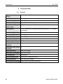
Technical data ............................................................................................................252
8.1
General ...........................................................................................................252
8.1.1
8.2
9
Installation recommendations .............................................................253
Sensor resistance values ................................................................................253
8.2.1
NTC 20 ...............................................................................................253
8.2.2
PT 1000 ..............................................................................................254
8.3
Sensor measurement ranges ..........................................................................255
8.4
Digital inputs....................................................................................................256
Log ..............................................................................................................................257
Index ....................................................................................................................................258
EN2H-0221GE51 R0213
9
Contents
10
SDC / DHC
EN2H-0221GE51 R0213
SDC / DHC
Software version
1
Software version
This documentation is valid for software version V 3.2 of your
control device. The software version is displayed after switch-on
for approx. 8 s. If you are using an older software version, please
contact your heating technician.
2
2.1
Safety instructions
Intended use
The SDC / DHC Smile family of controllers was designed for the
sole purpose of regulating and controlling hot-water, heating and
district heating systems (including hot-water production) that do
not exceed a maximum flow temperature of 120 °C.
2.2
Requirements for start-up
ATTENTION
The heating system must be complete and filled with water
so that the pumps do not run dry and the heating boiler is not
damaged.
The control equipment must be installed in accordance with
the installation instructions.
All electrical connections (voltage supply, burner, mixer
motor, pumps, sensor wiring etc.) must be carried out by the
technician in accordance with the applicable VDE regulations
and correspond with the circuit diagrams.
If floor heating is connected, a limiting thermostat must also
be installed in the flow line after the heating circuit pump.
This switches off the pumps at excessive flow temperatures.
Before starting up the controller, have the heating technician
check all requirements listed above.
NOTE
The current time and date are already set at the factory and are
backed up by a battery.
The time switch functions based on a basic program and the
control functions are preset for common heating systems with lowtemperature boilers.
EN2H-0221GE51 R0213
11
Safety instructions
SDC / DHC
2.2.1
Power supply
Do not disconnect the controller from the mains supply!
The battery for saving all individualised data is otherwise
unnecessarily strained. The frost-protection function of the
controller is deactivated.
2.2.2
Connection conditions
All electrical connection work may only be carried out by qualified
personnel!
2.2.3
Cable cross-sections
1.5 mm2 for all cables carrying 230 V (power supply, burner,
pumps, actuator).
0.6 mm2 for bus cables (recommended type J-Y(St)Y 2 x 0.6).
0.5 mm2 for sensors, selectors and analog signal cables.
2.2.4
Maximum cable lengths
Sensor, selector and analog inputs
We recommend using cables no longer than 200 m. Longer
connection lines could be used, but increase the risk of
interference.
Relay outputs
Unlimited cable length.
Bus connections
Max. length of 100 m from the first bus subscriber to the last one
(incl. wall modules).
2.2.5
Cable installation
Install cables for sensors apart from the cables carrying 230 V!
Branch boxes in the sensor cable must be avoided!
12
EN2H-0221GE51 R0213
SDC / DHC
Safety instructions
2.2.6
Grounding and zeroing
Local regulations on the connection of equipment must be
observed!
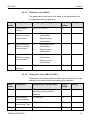
2.3
Hot-water temperature greater than 60 °C
ATTENTION
Note that there is a danger of scalding at all hot-water drawoff points (kitchen, bathroom etc.) in the following cases.
Add sufficient cold water in these cases.
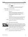
Automatic antilegionella mechanism
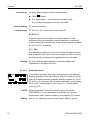
Manual mode /
Emission
measurement
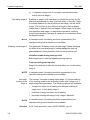
EN2H-0221GE51 R0213
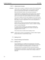
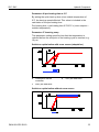
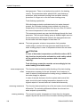
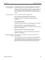
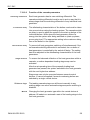
When the automatic anti-legionella mechanism is activated, the
hot water is automatically heated to the anti-legionella
temperature (65 °C at the factory) on the selected day and at the
selected time to kill any legionella bacteria found in the hot-water
tank.
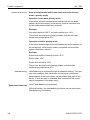
In the manual mode / emission measurement operating mode, the
hot water is heated up to the highest possible boiler temperature,
as the burner and all pumps are switched on and the mixer is
opened fully. There is an acute danger of scalding at all
connected hot-water draw-off points! Add sufficient cold water or
switch off the hot-water loading pump (at the switch of the pump,
if present). Heating and hot water are in unregulated continuous
operation. This operating mode is for special use by the chimney
sweep for emission measurement or if the controller is defective.
The high hot-water temperatures can be prevented, however, by
setting the boiler thermostat to a max. boiler temperature of
approx. 60 °C.
13
Safety instructions
SDC / DHC
2.4
Connection of accessory parts
WARNING
According to VDE 0730, a separator for each mains terminal
is to be provided in the voltage supply to the control
equipment. Observe the local regulations regarding
grounding and zeroing.
As soon as the mains voltage is applied to terminals 21, 22,
2, 6, 12 and 18, headers X3 and X4 can also carry mains
voltage.
If the heating circuit and hot-water loading pumps do not
have an On / Off switch, but manual switch-on and switch-off
capability is still desired, the appropriate switches must be
installed by the customer. All accessory parts (sensors,
selectors etc.) are to be connected to the respective circuit
diagram.
2.5
Maintenance and cleaning
The controller is maintenance-free. The device can be cleaned
externally with a moist (not wet) cloth.
14
EN2H-0221GE51 R0213
SDC / DHC
Safety instructions
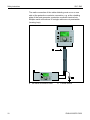
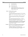
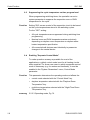
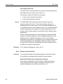
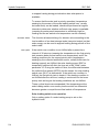
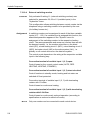
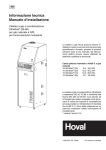
2.6
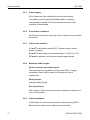
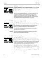
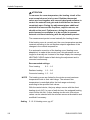
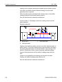
Safety precautions for EMC-compliant installation
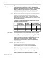
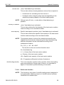
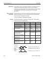
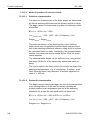
Mains lines and sensor/data bus lines must be installed separate
from each other. A minimum of 2 cm space must be present
between the lines. It is permissible to cross lines.
a
Mains 230 V AC
x
15 cm
b
Data bus line 12 V AC
y
2 cm
For control devices with their own mains connection, separate
installation of mains and sensor/bus lines must absolutely be
ensured. If cable ducts are used, they are to be provided with cutoff bridges.
EN2H-0221GE51 R0213
15
Safety instructions
SDC / DHC
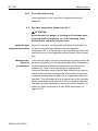
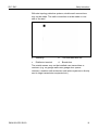
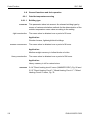
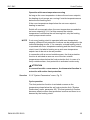
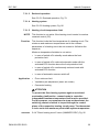
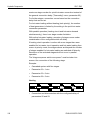
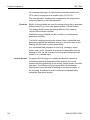
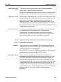
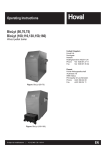
When installing control or wall devices, a minimum spacing of
40 cm to other electrical equipment with electromagnetic
emissions, e.g. relays, motors, transformers, dimmers, microwave
ovens and televisions, audio speakers, computers, cordless
telephones etc., is to be ensured.
x 40 cm
A minimum spacing of 40 cm is to be ensured between wall
devices and central devices. Multiple central devices in the data
bus system can be mounted directly next to one another.
16
EN2H-0221GE51 R0213
SDC / DHC
Safety instructions
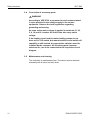
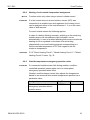
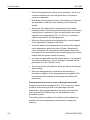
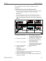
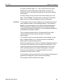
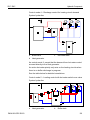
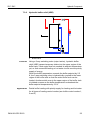
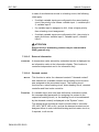
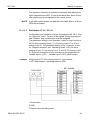
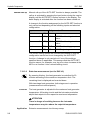
The mains connection of the heating system (boiler – panel –
control equipment) must be designed as a separate circuit.
Neither fluorescent lamps nor any machines which are potential
sources of interference may be connected/connectable.
a
Safety fuse 16 A
b
Boiler room emergency switch
c
Connect boiler room lighting and electrical outlets to
separate circuits only!
d
Wall devices
e
Heat generator
Shielded cables must be used for the data bus lines.
For a recommended layout, see 8 Technical data, pg. 252
EN2H-0221GE51 R0213
17
Safety instructions
SDC / DHC
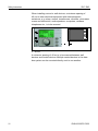
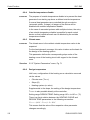
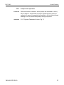
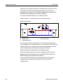
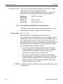
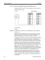
The earth connection of the cable shielding must occur on one
side at the protective conductor connection, e.g. at the cladding
plate of the heat generator, protective conductor terminal etc.
Multiple earth connections of a single cable are not permissible
(buzzing loop).
a
18
No earth connection here!
b Central device
EN2H-0221GE51 R0213
SDC / DHC
Safety instructions
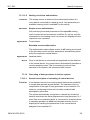
With star-topology data bus systems, double earth connections
may not be made. The earth connection must be made on one
side of the star!
a
Shielding
b
Two-lead data bus line
c
Distributor terminal
d
Branch box
The outside sensor may not be installed near transmitters or
receivers (e.g. on garage walls near garage door opener
receivers, amateur radio antennas, radio alarm systems or directly
next to large transmission equipment etc.).
EN2H-0221GE51 R0213
19
Overview
SDC / DHC
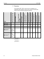
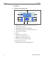
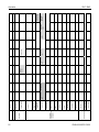
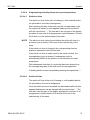
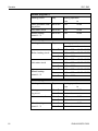
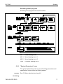
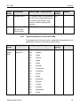
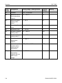
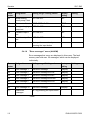
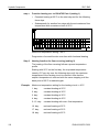
3
Overview
Variable output 1
Variable output 2
Tank loading pump
Mixed heating circuit 2
Mixed heating circuit 1
Variable output 3
Direct heating circuit
Burner stage 1
District heating valve
CLOSED
or
Type
Burner stage 2
Number of output relays
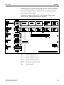
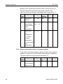
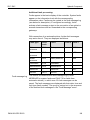
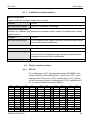
The modular SDC / DHC control device is available in an
installable switch cabinet version and a surface-mounted wall
version with the following equipment features:
SDC 3-10
3
–
x
x
–
–
x
SDC 3-40
3
–
–
–
x
–
–
–
–
SDC 7-21 1)
7
x
x
x
x
–
x
–
–
x
x
x
–
x
x
x
SDC 9-21 2)
7
x
+ two
variable
relays
x
x
x
x
x
x
x
SDC 12-31 3)
10
x
+ two
variable
relays
20
1)
DHC 43-1
2)
DHC 43-2
3)
DHC 43-3
–
EN2H-0221GE51 R0213
SDC / DHC
Abbreviations
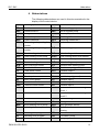
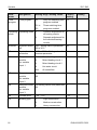
4
Abbreviations
The following abbreviations are used in this documentation/in the
display of the control device:
RED
Lowering operation
BS 2
Buffer sensor 2 (bottom)
OS
Outside sensor
BLP
Buffer loading pump
OS2
Outside sensor 2
RBP
Return bypass pump
FGS
Flue gas sensor
RP
Return pump
OT
Outside temperature
SD I
Switching differential I
BUS
System data bus
SD II
Switching differential II
OC1
Burner stage 1 operating hour TS
counter
Tank sensor
OC2
Burner stage 2 operating hour TLP
counter
Tank loading pump
DC
Direct heating circuit
SLS
Solar loading switch-over
DCP
Direct heating circuit pump
SLSS
Solar loading switch-over sensor
ECO
Switch-off operation
SFD
Solar forced dissipation
EHR
Electric heating rod
SLP
Solar loading pump
SFB
Solid fuel boiler sensor
STL
Stratified tank loading pump
SFR
Solid fuel buffer sensor
VO
Variable output (general)
FC
Fixed-value control
VO1
Variable output 1
SFP
Solid fuel pump
VO2
Variable output 2
PI
Pulse input
VI
Variable input (general)
BP
Boiler circuit pump
VI1
Variable input 1
CC
Constant control
VI2
Variable input 2
CRS
Collector return sensor
VI3
Variable input 3
CTBS
Collector tank/buffer sensor
FM1
Flow sensor of mixed heating
circuit 1
CFS
Collector flow sensor
FM2
Flow sensor of mixed heating
circuit 2
MM
Mixer motor
PHE
Parallel heat generator enable
MC
Mixed heating circuit
HG
Heat generator
MHP
Mixed heating circuit pump
HGS
Heat generator sensor
P1
Switching time program
WD
Wall device for room temperature
sensing
P2
Switching time program
HW
Hot water
P3
Switching time program
CIR
Circulation pump
BS
Buffer sensor (top)
CHP
Charging pump
EN2H-0221GE51 R0213
21
Operation
SDC / DHC
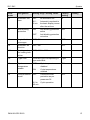
5
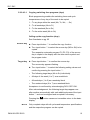
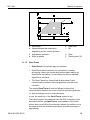
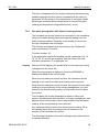
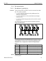
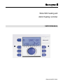
5.1
Operation
Display and operating elements
1 "Manual mode" / "Emission measurement" button (not on
district heating controllers)
2 "Operating modes" button (basic display)
3 "Switching time programs" / "Holiday programs" button
4 "System information" button
5 Display
6 Cover clip for service socket
7 "Daytime room temperature" button
8 "Night-time room temperature" button
9 "Daytime hot-water temperature" button
10 Input button (press / turn)
11 Operating mode symbols (heating programs)
22
EN2H-0221GE51 R0213
SDC / DHC
Operation
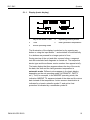
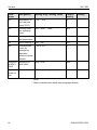
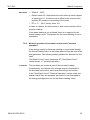
5.1.1
Display (basic display)
1
Day of the week / Date
4
Operating mode symbols
2
Time
5
Heat generator temperature
3
Active operating mode
The illumination of the display is switched on by pressing any
button or using the input button and switches off automatically
if no buttons are pressed for a longer period of time.
During start-up of the unit and after a power failure, a segment
test with automatic fault diagnosis is carried out. The respective
device type and the software version number then appear briefly.
The basic display that then appears shows the day of the week,
the date, the time and the heat generator temperature in
automatic mode. Different values appear in the basic display
depending on the set operating mode (AUTOMATIC, PARTY
etc.). Thus, for example, in the ABSENT operating mode, the
indication ABSENT TIL appears instead of the date and the return
date instead of the temperature. Active summer deactivation is
indicated by a beach umbrella symbol , and active frost
protection is indicated by a snowflake symbol .
EN2H-0221GE51 R0213
23
Operation
SDC / DHC
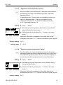
5.1.2
5.1.2.1
Operating elements
Input button (press / turn)
By pressing once, you can:
•
Confirm input / values
By pressing and holding (approx. 3 s), you can:
•
Switch to the menu-selection level
•
Move up one menu level
By turning the input button , you can:
5.1.2.2
Setting
•
Change values (clockwise increases called-up values,
anticlockwise decreases them)
•
Navigate through menus
"Daytime room temperature" button
Sets the desired room temperature (room setpoint) in automatic
mode during the heating cycles and in the PARTY and HEATING
operating modes. In operating mode 1, the set value for all
heating circuits is the same. In operating mode 2, the set value
applies for the respective heating circuit. To set the operating
mode, see 5.2.3.3 Operating mode, pg. 74.
► Press button.
► Set flashing room temperature specification to the desired
value by turning the input button .
► Confirm set value by pressing the button or the input
button .
Alternative: Automatic acceptance of the value after the set
information time (see 5.1.2.7 "System information" button, pg. 35).
Factory setting
Setting range
24
20 °C
5 ... 30 °C
EN2H-0221GE51 R0213
SDC / DHC
Operation
5.1.2.3
"Night-time room temperature" button
Sets the lowered room temperature in automatic mode between
the heating cycles and in the ABSENT and RED. HEATING
operating modes.
In operating mode 1, the set value for all heating circuits is the
same. In operating mode 2, the set value applies for the
respective heating circuit. To set the operating mode, see
5.2.3.3 Operating mode, pg. 74.
Setting
► Press button.
► Set flashing room temperature specification to the desired
value by turning the input button .
► Confirm set value by pressing the button or the input
button .
Alternative: Automatic acceptance of the value after the set
information time (see 5.1.2.7 "System information" button, pg. 35).
Factory setting
Setting range
5.1.2.4
16 °C
5 ... 30 °C
"Daytime hot-water temperature" button
Sets the daytime hot-water temperature during the hot-water
operational-readiness times in automatic mode and in the PARTY
and HEATING operating modes. This set value also applies for
exclusively hot-water operation (manual summer operation).
Setting
► Press button.
► Set flashing hot-water temperature to the desired value by
turning the input button .
► Confirm set value by pressing the button or the input
button .
Alternative: Automatic acceptance of the value after the set
information time (see 5.1.2.7 "System information" button, pg. 35).
Factory setting
EN2H-0221GE51 R0213
50 °C
25
Operation
SDC / DHC
Setting range
One-time hot-water
circuit loading
5.1.2.5
5 °C (hot-water economy temperature) ... Maximum hot-water
heater temperature limit (service setting)
Pressing and holding (approx. 3 s) the button brings you to
the reload function, where the reload time can be set in minutes.
With a reload time of 0 minutes, loading is started once and the
hot-water tank is loaded to the daytime setpoint. The time for this
superimposed hot-water circuit loading can be set between 0 and
240 minutes. The current week program is superimposed here.
"Operating mode" button (basic display)
Sets the operating mode and returns to the basic display from
every operating level.
26
EN2H-0221GE51 R0213
SDC / DHC
Operation
Overview of the operating modes
Symbol
Operating mode
Display
Setting
ABSENT
P1 (P2, P3)*, return
date
PARTY
P1 (P2, P3)*,
party end time
AUTOMATIC
P1 (P2, P3)*
SUMMER
P1(P2, P3)*
HEATING
RED. HEATING
STANDBY
* P2 and P3 only after enabling, see "System Parameters"
menu, parameter 2 = P1 to P3
EN2H-0221GE51 R0213
27
Operation
SDC / DHC
The selected operating mode appears in plain text, whereby a
marking at the bottom edge of the display points to the respective
operating mode symbol at the same time. In operating mode 1,
the set value for all heating circuits is the same. In operating
mode 2, the set value applies for the respective heating circuit. To
set the operating mode, see 5.2.3.3 Operating mode, pg. 74.
Setting
► Press
button.
► Select operating mode by turning the input button . The
marking is located above the corresponding operating mode
symbol.
► Confirm set operating mode by pressing the
button or the
input button .
► With short-term operating modes (ABSENT, PARTY), set the
desired value by turning the input button and confirm with
the
button or the input button .
Alternative: Automatic acceptance of the value after the set
information time (see 5.1.2.7 "System information" button, pg. 35).
Return to the basic
display
Press the
button for approx. 3 s to return to the basic display
from any operating level.
NOTE
Holiday mode is set via the "Switching time programs / Holiday
programs" button (see 5.1.2.6 "Switching time programs / Holiday
programs" button, pg. 33).
5.1.2.5.1
Absence mode (short-term program)
With the ABSENT operating mode, heating operation is
temporarily deactivated and protected from frost during brief
absences. During the absence, all heating circuits are adjusted to
the specified lowered room temperature. Once the set time
expires, the heating circuits automatically return to the operating
mode that was active before the switch to the absence operation.
Short-term programs such as PARTY or ABSENT are skipped
here.
Setting
Application
28
See 5.1.2.5 "Operating mode" button (basic display) , pg. 26
Short absence while heating operation is active.
EN2H-0221GE51 R0213
SDC / DHC
Operation
Cancellation
An active absence program can be cancelled in case of early
return.
► Press
button.
► Turn input button and switch to automatic operation.
The active absence program has been cancelled.
Factory setting
Setting range
P1 as from activation
P1 (P2, P3) / 0.5 to 24 h to the current time
P1 (P2, P3)
Program-controlled resumption of heating operation. After
activation of the absence program, heating operation is
interrupted until the following switch-on time of the current
automatic program P1 (or P2 or P3, if enabled).
0,5 ... 24 h
The set value is added on to the current time and represents the
return time. When the absence program is called up again, the
last set value is saved and suggested as the initial value.
Display
5.1.2.5.2
An active absence program appears in the basic display with
information on the return time.
Party mode (short-term program)
Party mode causes one-time intermediate heating of all heating
circuits up to a specified point in time and bridges an upcoming or
already active absence cycle totally or partially. Once the set time
expires, the heating circuits automatically return to the operating
mode that was active before the party program. Short-term
programs such as ABSENT or PARTY are skipped here.
Setting
Application
EN2H-0221GE51 R0213
See 5.1.2.5 "Operating mode" button (basic display) , pg. 26
One-time extension of heating operation or intermediate heating
during lowering operation outside the schedule.
29
Operation
SDC / DHC
Cancellation
An active party program can be cancelled early.
► Press
button.
► Turn input button and switch to automatic mode.
The active party program has been cancelled.
Factory setting
Setting range
P1 as from activation
P1 (P2, P3) / 0.5 to 24 h to the current time P1
P1 (P2, P3)
Program-controlled resumption of heating operation. After
activation of the party program, heating operation is continued
until the following switch-on time of the current automatic program
P1 (or P2 or P3, if enabled)
0,5 ... 24 h
The set value is added on to the current time and represents the
end of the party time. When the party program is called up again,
the last set value is saved and suggested as the initial value.
Display
5.1.2.5.3
An active party program appears in the basic display with
information on the party end time.
Automatic mode
In automatic operation, max. three time programs with different
heating operation times are available. They are called up during
start-up as factory-set and unlosable default programs P1, P2 or
P3 and can, if necessary, be overwritten with their own switching
times in the "Timeprograms" menu (see 5.2.2 "Timeprograms"
menu, pg. 55).
NOTE
Setting
30
Default programs P2 and P3 cannot be selected until the
PROGRAM = P1 to P3 parameter is enabled in the "System
Parameters" menu. Without enabling, only program P1 is active.
See 5.1.2.5 "Operating mode" button (basic display) , pg. 26
EN2H-0221GE51 R0213
SDC / DHC
Operation
Disabling / enabling default program P2 to P3
Disabling
"System Parameters" menu, program parameter = P1. All heating
circuits and the hot-water circuit solely refer to the default /
individually programmed switching times in the program P1
parameter. Program P1 does not appear in the display in this
operating mode (see 5.2.2 "Timeprograms" menu, pg. 55 and
5.2.3.2 Time program, pg. 72).
Enabling
"System Parameters" menu, program parameter = P1 to P3 (see
5.2.2 "Timeprograms" menu, pg. 55 and 5.2.3.2 Time program,
pg. 72).
Display
An active automatic program appears in the basic display with the
current date and time. If default programs P2 and P3 were
enabled, the corresponding symbol, , or , is also
displayed depending on the selected program. The symbols are
only displayed with the time program P1 to P3 active.
5.1.2.5.4
Manual summer operation (excluding heating operation)
With manual summer operation, only the hot-water circuit remains
operation and controls the heat generator temperature based on
the specified hot-water temperature and the specified hot-water
switching time program. Heating operation is stopped, and
protection from frost is provided. This feature is only available
when control mode is set to 1.
Setting
See 5.1.2.5 "Operating mode" button (basic display) , pg. 26
Disabling / enabling default programs P2 to P3
Disabling
"System Parameters" menu, program parameter = P1. All heating
circuits and the hot-water circuit solely refer to the default /
individually programmed switching times in the time program = P1
parameter. Program P1 does not appear in the display in this
operating mode (see 5.2.2.1 Selection of the control circuit, pg. 56
and 5.2.3.2 Time program, pg. 72).
EN2H-0221GE51 R0213
31
Operation
SDC / DHC
Enabling
"System Parameters" menu, program parameter = P1 to P3 (see
5.2.2.1 Selection of the control circuit, pg. 56 and 5.2.3.2 Time
program, pg. 72).
Display
Manual summer operation appears in the basic display with the
information SUMMER. If default programs P2 and P3 were
enabled, the corresponding symbol, , or , is also
displayed depending on the selected program. The symbols are
only displayed with the time program P1 to P3 active.
5.1.2.5.5
Continuous heating operation
The HEATING operating mode ensures continuous heating
operation without time limitations based on the specified daytime
room temperature. Hot-water production occurs continuously
based on the specified daytime hot-water temperature.
NOTE
The HEATING operating mode remains active until another
operating mode is activated.
Display
Activated continuous heating operation appears in the basic
display with the information HEATING.
5.1.2.5.6
Continuous lowering operation
The RED. HEATING operating mode causes continuously
reduced heating operation based on the specified lowered room
temperature. On the heating circuit levels, the reduced operating
mode ECO (frost-protected deactivation mode) or RED (lowering
mode) is set accordingly. The minimum temperature limit of the
respective heating circuit must be taken into account.
See the "Direct Circuit" or "Mixed Heating Circuit 1" / "Mixed
Heating Circuit 2" menu, reduced parameter = reduced operation
and 12 parameter = minimum temperature limit.
Hot-water production occurs continuously based on the specified
hot-water economy temperature (see "DHW" menu, hot water
parameter = hot water at night).
32
EN2H-0221GE51 R0213
SDC / DHC
Operation
NOTE
Display
The RED. HEATING operating mode remains active until another
operating mode is activated.
Activated continuous lowering operation appears in the basic
display with the information RED. HEATING.
In standby mode, the entire system is switched off and protected
from frost (all frost-protection functions active).
Hot-water production is disabled and protected from frost. At
storage temperatures below 5 °C, a reload to up to 8 °C takes
place.
Application
NOTE
Total deactivation of heating and hot water with full building
protection.
The heat generator and hot-water production remain in operation
in case of external demand or demand by other heating circuits
on the bus network. The heating circuit pumps are switched on
briefly every day (pump anti-blocking protection).
The standby mode remains active until another operating mode is
activated.
Display
5.1.2.6
Activated continuous standby mode appears in the basic display
with the information STANDBY.
"Switching time programs / Holiday programs" button
Using this button, you can create individualised switching time
programs for heating and hot-water operation and set holiday
mode.
See 5.1.2.6.1 Holiday mode, pg. 34 and 5.2.2 "Timeprograms"
menu, pg. 55.
EN2H-0221GE51 R0213
33
Operation
SDC / DHC
5.1.2.6.1
Holiday mode
In holiday mode, the heating circuits can be switched off and
protected from frost or operated based on the settings for the RED.
HEATING operating mode for the duration of the holiday based on
the presetting ("Direct circuit" or "Mixed heating circuit 1" / "Mixed
heating circuit 2" menu, parameter 25 = holiday operating mode).
Setting
► Press
button.
The menu-selection level Switching time programs / Holiday
programs appears in the display.
► Turn input button to the left.
HOLIDAY appears in the display.
► Press input button .
HOLIDAY 01 appears in the display.
► Press input button .
The year flashes in the display.
► Set year with the input button .
► Press input button .
The day on which the holiday is to begin flashes in the display.
► Set the day the holiday will begin with the input button .
► Press input button .
TIL - - appears in the display.
► Set the day you will return from holiday with the input
button .
► Press input button .
The desired holiday timeframe is saved.
You can now enter additional holiday timeframes (up to 15 holiday
blocks).
Application
34
Longer absence while heating operation is active.
EN2H-0221GE51 R0213
SDC / DHC
Operation
Control during
holidays
Cancellation
At outside temperatures below the frost-protection limit (see
5.2.3 "System Parameters" menu, pg. 71) the heating circuits are
controlled as follows:
•
Without wall devices: Based on a lowered room temperature
specification of 3 °C.
•
With wall devices: Based on the room frost-protection limit of
the respective heating circuit of 10 °C (see "Direct Heating
Circuit" or "Mixed Heating Circuit 1", "Mixed heating circuit 2"
menu, parameter 08 = room frost-protection limit).
An active holiday program can be cancelled in case of early
return.
► Press and hold the
button for approx. 3 seconds until the
following appears in the display: "Holiday off".
Factory setting
Setting range
Display
5.1.2.7
Current date
Current date... (current date + 250 days)
An active holiday program appears in the basic display with
information on the return date.
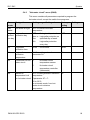
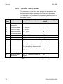
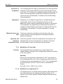
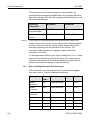
"System information" button
Calls up system information, such as temperatures and counter
data.
The information on the outside temperature appears first after the
button is pressed. Turning the input button causes the
system temperatures and the counter and consumption states
and operating states of the connected system components to
appear. Pressing the input button causes the respective
setpoint values to appear.
Exceptions
NOTE
EN2H-0221GE51 R0213
Collector flow temperature:
No setpoint
Solar tank temperature:
No setpoint
Outside temperature:
Averaged value
The displayed information (see the following example) is
independent of the installed or enabled system components and
control circuits.
35
Operation
SDC / DHC
Operating overview
36
EN2H-0221GE51 R0213
SDC / DHC
Operation
Setting time for
automatic return
If the button is pressed and held for approx. 3 s, the INFO
TIME parameter appears.
With this parameter, the time it takes for automatic return to the
basic display can be specified.
Setting range
Factory setting
5.1.2.7.1
OFF
No return. The last selected information display
continuously remains in the basic display until the
next change.
1 ... 10 min
Automatic return from the information level after the
specified time (in 0.5 minute increments).
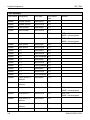
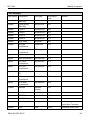
OFF
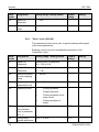
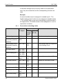
Temperature displays
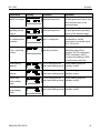
Information
Display
Outside
temperature (1)
Determined
value/Current
value
Outside
temperature (1)
Min./max. value Outside sensor
(0:00 to 24:00
connected and no fault
hours)
message
Outside
temperature (2)
Determined
value/Current
value
Outside
temperature (2)
Min./max. value OS2 connected, no fault
message
(0:00 to 24:00
hours)
EM-SET (energy
management
setpoint)
"EM-SET"
Heat generator
temperature (1)
Setpoint/Actual
value
Heat generator
specified
Code 1 only appears if BS2
is present
Heat generator
temperature (2)
Setpoint/Actual
value
Variable input
configured as BS2
Connection BS2 to variable
input VI1, VI2 or VI3
EN2H-0221GE51 R0213
Condition
Variable input
configured as OS2
Remarks
Connection OS2 to variable
input VI1, VI2 or VI3
Highest hot-water setpoint
and highest heating circuit
setpoint in the system
37
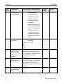
Operation
SDC / DHC
Information
Display
Condition
Remarks
Return
temperature
Setpoint/Actual
value
Return sensor
connected and one of
the functions for return
increase is active
Connection of return sensor
to associated variable input
1 or 2, VI can no longer be
called up
Flow sensor of
district heating
valve VF1
Setpoint/Actual
value
With district heating
controllers
Return sensor of
district heating
valve VFB
Setpoint/Actual
value
With district heating
controllers
External heat
Disabled mode
generator disable ON/OFF
External heat generator External contact to variable
input VI1, VI2 or VI3
disable (VI1-VI3)
specified
Flue gas
temperature
Limit signal
value/Actual
value
Variable input
configured as AGF
Connection only to variable
input VI1
Water heater
temperature (1)
Setpoint/Actual
value
If hot-water circuit is
present
Code 1 only appears if SF2
is present
Water heater
temperature (2)
Setpoint/Actual
value
Variable input
configured as SF2
Connection to variable input
VI1, VI2 or VI3
Water heater
temperature
controller
Load condition
ON/OFF
Thermostat mode
Thermostat instead of sensor
(SF1 only)
Demand via
switching contact
(VI1)
Demand
ON/OFF
VI configured as
demand contact
External contact to variable
input VI1, VI2 or VI3
Demand via
switching contact
(VI2)
Demand
ON/OFF
VI configured as
demand contact
External contact to variable
input VI1, VI2 or VI3
Demand via
switching contact
(VI3)
Demand
ON/OFF
VI configured as
demand contact
External contact to variable
input VI1, VI2 or VI3
Mixed heating
circuit 1 flow
temperature
Setpoint/Actual
value
Mixed heating circuit 1
specified
Mixed heating
circuit 1 return
temperature
Actual value
Return temperature with
return maximum limit
38
EN2H-0221GE51 R0213
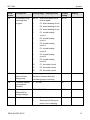
SDC / DHC
Operation
Information
Display
Condition
Mixed heating
circuit 2 flow
temperature
Setpoint/Actual
value
Mixed heating circuit 2
specified
Mixed heating
circuit 2 return
temperature
Actual value
Return temperature with
return maximum limit
Direct heating
circuit room
temperature
Setpoint/Actual
value
Direct heating circuit
specified
Setpoint inquiry without room
temperature sensing:
Current room setpoint of
direct heating circuit
Mixed heating
circuit 1 room
temperature
Setpoint/Actual
value
Mixed heating circuit 1
specified
Setpoint inquiry without room
temperature sensing:
Current room setpoint of
mixer heating circuit 1
Mixed heating
circuit 2 room
temperature
Setpoint/Actual
value
Mixed heating circuit 2
specified
Setpoint inquiry without room
temperature sensing:
Current room setpoint of
mixed heating circuit 2
Direct heating
circuit thermostat
function
DC
THERMOSTAT
Thermostat function
specified
OFF = temperature limit
exceeded
Mixed heating
circuit 1
thermostat
function
MC1
THERMOSTAT
Thermostat function
specified
OFF = temperature limit
exceeded
Mixed heating
circuit 2
thermostat
function
MC2
THERMOSTAT
Thermostat function
specified
OFF = temperature limit
exceeded
Solid fuel boiler
temperature
Actual value
VO1/2 configured as
solid fuel loading pump
Connection of FSKF to
associated variable input 1
or 2, VI can no longer be
called up
Solid fuel boiler
buffer
temperature
Actual value
EN2H-0221GE51 R0213
Remarks
Solid fuel loading pump at
variable output, corresponds
to KSPF or FPF, depending
on configuration
39
Operation
SDC / DHC
Information
Display
Condition
Remarks
Buffer tank
temperature at
top
Setpoint/Actual
value
VO1/2 configured as
buffer tank loading
pump
Connection of PF1 to
associated variable input 1
or 2, VI can no longer be
called up
Buffer tank
temperature at
bottom
Setpoint/Actual
value
VO1/2 configured as
buffer tank loading
pump
Connection of PF2 to
variable input VI1, VI2 or VI3
Solar collector
flow temperature
Actual value
VO1/2 configured as
Special sensor
solar tank loading pump
Solar tank
temperature
Actual value
VO1/2 configured as
solar tank loading pump
Solar collector
return
temperature
Actual value
VO1/2 configured as
Connection of KRLF to
solar tank loading pump variable input VI1, VI2 or VI3
Solar tank switch- Actual value
over temperature
Solar loading valve activated
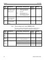
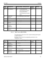
5.1.2.7.2
Operating states
An operating state inquiry occurs after the information menu is
called up by turning the input button anti-clockwise. The following
displays appear only under the specified conditions and may not
be available (depends on device version).
Information
Direct heating
circuit operating
status
Display
Condition
Direct heating circuit
specified
Remarks
Heating program: Holiday,
Absent Til, Party Til, Auto,
Summer, Heating, Red.
Heating, Standby
Switching time program:
P1 (P2, P3) control mode:
Day, RED, ECO
Mixed heating
circuit 1 operating
status
Mixed heating circuit 1
specified
Heating program: Holiday,
Absent Til, Party Til, Auto,
Summer, Heating, Red.
Heating, Standby
Switching time program:
P1 (P2, P3) control mode:
Day, RED, ECO
40
EN2H-0221GE51 R0213
SDC / DHC
Information
MC1 actuator
operating status
Operation
Display
Condition
Mixed heating circuit 1
specified
Remarks
Mixed heating circuit 1
opens, closes or does not
move
Mixed heating circuit 2
specified
Heating program: Holiday,
Absent Til, Party Til, Auto,
Summer, Heating, Red.
Heating, Standby
Mixed heating
circuit 2 operating
status
Switching time program:
P1 (P2, P3) control mode:
Day, RED, ECO
MC2 actuator
operating status
Mixed heating circuit 2
specified
Mixed heating circuit 2
opens, closes or does not
move
District heating
valve operating
status
District heating valve
opens, closes or does
not move
Heat generator
operating status
(st. 1)
Heat generator specified Information on the switching
state of the multi-stage heat
generator
Heat generator
operating status
(st. 2)
Operating status
of modulating
heat generator
Multi-stage heat
generator specified
Information on the switching
state of the second stage of
the heat generator
Modulating burner
specified
If a single-stage modulating
heat generator is set,
display of actual value and
setpoint occurs in %
Hot-water circuit
specified
Hot-water program: Holiday,
Absent Til, Party Til, Auto,
Summer, Heating, Red.
Heating, Standby
Hot-water circuit
operating status
With district heating
controllers
Switching time program:
P1 (P2, P3) control mode:
Day, RED, ECO
EN2H-0221GE51 R0213
41
Operation
Information
Function and
status of direct
heating circuit
pump
SDC / DHC
Display
Condition
Outputs specified
Function and
status of variable
output 1
based on function
Outputs specified
Function and
status of variable
output 2
based on function
Outputs specified
based on function
Remarks
Solar (SOP), circulation
(CIR), electric heating rod
(ELH), feeder (CHP), boiler
circuit (KKP1, KKP2), fault
message (SMA), return
(RLP), buffer (PLP), solid
fuel (FSP), heating circuit
(HKP), constant (KP), timer
(CLOCK)
Solar (SOP), circulation
(CIR), electric heating rod
(ELH), feeder (CHP), boiler
circuit (KKP1, KKP2), fault
message (SMA), return
(RLP), buffer (PLP), solid
fuel (FSP), heating circuit
(HKP), constant (KP), timer
(CLOCK)
Solar (SOP), circulation
(CIR), electric heating rod
(ELH), feeder (CHP), boiler
circuit (KKP1, KKP2), fault
message (SMA), return
(RLP), buffer (PLP), solid
fuel (FSP), heating circuit
(HKP), constant (KP), timer
(CLOCK)
District heating
valve volume flow
Heat generator specified With district heating
controllers
Heat generator specified With district heating
controllers
District heating
valve capacity
Heat generator
(1) start-ups
Heat generator specified Information on the number
of heat generator switch-ons
(burner start-ups) of the
multi-stage heat generator.
Operating hours
of heat generator
(1)
Heat generator specified Information on the number
of heat generator operating
hours of the multi-stage heat
generator.
42
EN2H-0221GE51 R0213
SDC / DHC
Information
Heat generator
switch-ons stage
2
Operation
Display
Heat generator
operating hours
stage 2
Test temperature
for measurement
purposes
Operating status
of ext. switching
modem
Condition
Multi-stage heat
generator specified
Remarks
Information on the number
of heat generator switch-ons
(burner start-ups) of the
second stage.
Multi-stage heat
generator specified
Information on the number
of heat generator operating
hours of the second stage.
KVT sensor connected
and VI configured.
Controller-independent test
temperature, sensor
connection to variable input
VI1, VI2 or VI3
VI configured as
switching modem
Control modes based on the
switching state of the
modem: AUTO (automatic)
STBY (standby), HEAT
(continuous heating), RED
(continuously reduced).
Solar heating
capacity
VO1/2 configured as
Solar loading pump at
solar tank loading pump variable output
Solar heat
balance
VO1/2 configured as
Solar loading pump at
solar tank loading pump variable output
Switch-ons
Solar loading
pump
VO1/2 configured as
Solar loading pump at
solar tank loading pump variable output
Operating hours
Solar loading
pump
EN2H-0221GE51 R0213
VO1/2 configured as
Solar loading pump at
solar tank loading pump variable output
43
Operation
SDC / DHC
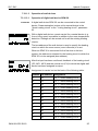
5.1.2.8
5.1.2.8.1
"Manual mode" / "Emission measurement" button
Manual mode
If this button is pressed and held longer than 5 s in the basic
display, the controller is switched to manual mode. In this
operating mode, the required heat generator temperature is
specified manually with the input button according to the
respective heating need.
A controller set to manual mode has no effect in heat circuit
expansion.
The heat generator setpoint is set between the minimum and
maximum heat generator temperatures and appears flashing at
the bottom left-hand side. The current heat generator temperature
appears statically on the right-hand side in the basic display. The
set switching differential corresponds to the value of automatic
control and is symmetrical to the set value.
Application
NOTE
Controller malfunctions (emergency operation), errors
The maximum heat generator temperature limit is paramount to
the heat generator switching differential and stops the heat
generator in case of exceedance.
With control devices operated purely as a heating circuit
expansion, the setting of the temperature has no effect.
The last value to which the control device adjusted the heat
generator temperature appears as a recommendation.
Cancellation
44
Press
button or
operating mode.
button, to return to the last selected
EN2H-0221GE51 R0213
SDC / DHC
Operation
5.1.2.8.2
Emission measurement (not with district heating controllers)
ATTENTION
Emission measurements may only be carried out by the
chimney sweep.
Pressing the
button controls the heat generator for a duration
of 20 min based on the set maximum temperature limit. The
remaining time is displayed and counted down.
With two-stage heat generators, both stages are in operation
(measurement at nominal output).
Function
The heat generator is adjusted to the maximum heat generator
temperature. All heating circuits and the hot-water production
adjust their setpoint to the respective maximum temperature.
ATTENTION
There is a danger of scalding by hot water, as the hot-water
temperature can exceed the set setpoint temperature.
Application
Cancellation
Emission measurement by the chimney sweep.
Emission measurement can be cancelled at any time with the
or
EN2H-0221GE51 R0213
button.
45
Operation
SDC / DHC
5.1.2.9
Access to the technician / OEM area
Entering a technician or OEM code enables additional setting
options in the parameter menu. The technician code is:
For access to the OEM area, please ask your field-service contact
partner.
Procedure:
► Press the
and
buttons simultaneously. The first
number of the 4-digit code flashes.
► Set the first code number by turning the input button.
► Press the input button. The second number flashes.
► Enter all remaining code numbers as described in Steps 2 and
3. After entering the last code number, the controller is
enabled for the respective area (technician or OEM).
► Press and hold the rotary button longer than 3 seconds. You
reach the menu-selection level and can enter / modify
parameters.
Pressing the
button jumps back to the previous selection.
Pressing the
button, pressing and holding the input button
longer than 3 seconds or waiting until the set info time expires
causes a jump back to the basic display.
46
EN2H-0221GE51 R0213
SDC / DHC
Operation
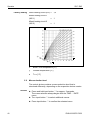
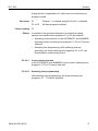
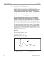
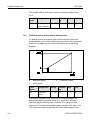
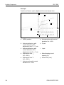
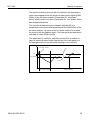
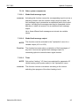
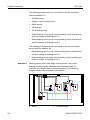
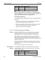
5.1.2.10
Heating curve
Determines the heating curve for the heating circuits.
The heating curve describes the relationship of the flow
temperature change to the outside temperature change. With a
larger heating surface, such as with floor heaters, the heating
curve has a less extreme slope than with a smaller heating
surface (e.g. radiators).
The set value refers to the lowest outside temperature used for
heat demand calculation.
ATTENTION
This parameter must be set by the technician and should no
longer be changed.
Setting
► Press and hold input button for 3 s.
► Turn the input button to select the desired heating circuit (HC,
MC-1 or MC-2) and confirm it by pressing the input button .
The design temperature (system) appears at the bottom righthand side of the display.
► Press input button .
The slope of the heating curve appears at the bottom left-hand
side of the display.
► Set the flashing heating curve value by turning the input button
(design temperature also flashes and is changed
automatically depending on the slope of the heating curve).
► Confirm by pressing the input button .
Alternative: Automatic acceptance of the value after the set
information time (see 5.1.2.7 "System information" button, pg. 35).
► Press
Setting range
EN2H-0221GE51 R0213
button to return to the basic display.
0,2 ... 3,5
47
Operation
SDC / DHC
Factory setting
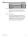
5.2
Direct heating circuit (HC) =
1,5
Mixed heating circuit 1
(MC-1)
=
1
Mixed heating circuit 2
(MC-2)
=
1
x
Boiler / flow temperature [°C]
y
Outside temperature [°C]
a
Troom [°C]
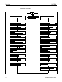
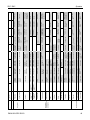
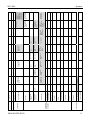
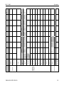
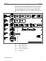
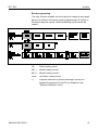
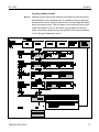
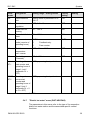
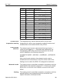
Menu-selection level
The control device contains a menu-selection level that is
structured differently, depending on the respective device version.
Access
► Press and hold input button for approx. 3 seconds.
The menu selection always begins with the TIME – DATE
menu.
► Turn input button to select additional menus.
► Press input button to confirm the selected menu.
48
EN2H-0221GE51 R0213
EN2H-0221GE51 R0213
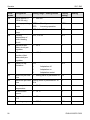
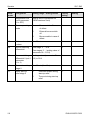
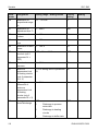
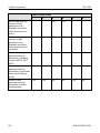
Service functions
Configuration
(heating circuits,
control paths)
Configuration
Programming
Hot water at night
Reduced operation Heating system
Heating curve
slope
Heating curve
slope
Direct heating
circuit
Mixed heating
circuit 1/2
Central device
address
Heat generator
test
Data bus
Relay test
Outside sensor
Direct heating
circuit pump test
Switching
differential
Cascading
Sensor calibration
Mixed heating
circuit 1 bus
authorisation
Direct heating
circuit bus
authorisation
Regulation
Total flow control
Fault message 1
Switch-off delay
Connection delay
Min. temperature
Buffer
Fault messages 1/2
Regulation
Min. temperature
Solid fuel
Fault message 3
Hot-water sensor
Heat generator
sensor
Mixed heating
circuit pump 1 test
Fault message 5
Mixed heating
circuit 2 flow
sensor
Mixed heating
circuit 1 flow
sensor
Mixed heating
circuit pump 2 test
Stage reversal
Forced discharge
Fault message 4
Mixer motor 1 test
Switch-over
capacity of stage
sequence
Mixed heating
circuit 2 bus
authorisation
Boiler temperature Buffer switching
offset
differential
Heat generator
cycle disable
Switch-on
differential
Switch-off
differential
Buffer maximum
temperature limit
Adjustment time
Solar loading
pump minimum
runtime
Fault message 2
Max. temperature
Max. temperature
Switch-off
differential
Switch-on
differential
Solar
Follow-up time of
pump
Switch-off
differential
Return
temperature
setpoint
Return increase
Secondary flow
boost
District heating
valve minimum
travel
Maximum flow
temperature
setpoint limit
Offset
District heating
Maximum
temperature limit
Minimum
temperature limit
Start-up protection
Design
Collector sensor
Fault message 6
Mixer motor 2 test
Guidance stage
Switch-on
differential
extension
Control mode
Runtime of district
heating valve 1
Sensor control
mode
Max. temperature
Transducer for hotlimit for hot-water
water circuit
circuit
Legionella
protection
temperature
Room factor
Variable output 2
7
Variable input 1
8
Variable input 2
9
Starting point of
flexible district
heating return
temperature
Max. return
temperature
setpoint
Switch-over of
base load with
grouping
Buffer start-up
protection
Buffer sensor of
collector
Fault message 7
Sensor of variable
input 1
Fault message 8
Tank loading pump Variable output 1
test
test
Peak-load stage
Follow-up switchoff differential
Heat generator
cycle disable
Runtime of district
heating valve 2
Sensor of variable
input 2
Fault message 9
Variable output 2
test
Quick hot-water
connection
Buffer discharge
protection
Heat balance
Burner switching
differential II
Burner switching
differential I
Minimum burner
runtime
Priority parallel
switch-over
Room thermostat
function
Room frost
protection limit
Heating limit
Heating limit
Temperature offset
of heat generator
during hot-water
circuit loading
Room thermostat
function
Tank discharge
protection
Room frost
protection limit
Hot-water circuit
control mode
Demand contact
Demand contact
Demand contact
module for variable module for variable module for variable Climate zone
input 1
input 2
input 3
System frost
protection
Room factor
Heat generator
6
Direct heating
Variable output 1
circuit pump output
5
Summer/Heat limit
Mixed heating
circuit 2 output
Switch-over
4
Room connection
Reduced operation Heating system
Room connection
Legionella
protection time
Legionella
protection day
Hot water
Operating mode
Mixed heating
circuit 1 output
Day - Month
3
Time program
Language
selection
System parameter
Hot-water loading
pump output
Hydraulic
schematic
Hydraulics
2
Year
1
Time
0
Date
Parameter
SDC / DHC
Operation
49
50
Service functions
Configuration
(heating circuits,
control paths)
Configuration
Programming
Sensor calibration
Fault messages 1/2
Relay test
Data bus
Cascading
Total flow control
Buffer
Solid fuel
Solar
Return increase
District heating
Heat generator
Mixed heating
circuit 1/2
Direct heating
circuit
Hot water
System parameter
Hydraulics
Date
Parameter
Constant
temperature
setpoint
Constant
temperature
setpoint
Boiler start-up
discharge stage II
Assignment of
outside sensor
Connection delay
stage II
Sensor of variable
input 3
Fault message 10
System
Buffer control
mode
Reset heat
balance
Max. return
temperature
setpoint during
hot-water circuit
loading
Fault message 12
Density of medium
Calibration of
thermal output
Minimum
temperature limit
Minimum
temperature limit
Circulation pump
switching time
program
Anti-blocking
function
12
Mixed heating
Direct heating
circuit 1 room
circuit room sensor
sensor
Fault message 11
Buffer loading
pump extended
running time
Volume flow
District heating
valve return limit
Hot-water loading
pump extended
running time
Switching
differential of hotwater circuit
Assignment of
outside sensor
Automatic exit time
Indirect return
increase via mixed
heating circuit
11
Building type
Variable input 3
10
Mixed heating
circuit 2 room
sensor
Fault message 13
Heat capacity of
medium
Calibration of
volume flow
Flow time of boiler
circuit pump or
parallel heat
generator enable
Maximum
temperature limit
Maximum
temperature limit
Circulation pump
economy interval
pause
Logical fault
messages
13
Locking code for
heating technician
15
Fault message 14
Max. thermal
output
Fault message 15
Solar loading
switch-over test
cycle
Max. volume flow
Boiler circuit pump Charging pump
extended running extended running
time
time
Temperature offset Follow-up time of
pump
of heating circuit
Temperature offset Follow-up time of
pump
of heating circuit
Economy interval
cycle
Automatic set
function
14
Fault message 16
Switch-over
temperature
Flue gas
temperature
monitoring
Screed function
Screed function
Circulation pump
Type code
16
Fault message 17
Flue gas
temperature limit
Return maximum
temperature limit
Behaviour of heat
generator during
extended running
time
17
19
Fault message 18
P-part Xp
Fault message 19
Modulation of
proportional part
Xp
Sample time Ta
Cycle temperature Frost protection
enable
mode
18
Operation
SDC / DHC
EN2H-0221GE51 R0213
EN2H-0221GE51 R0213
Service functions
Configuration
(heating circuits,
control paths)
Configuration
Programming
Sensor calibration
Fault messages 1/2
Relay test
Data bus
Cascading
Total flow control
Buffer
Solid fuel
Solar
Return increase
District heating
Heat generator
Mixed heating
circuit 1/2
Direct heating
circuit
Hot water
System parameter
Hydraulics
Date
Parameter
Fault message 20
I-part Tn
20
Actuator end
position function
22
Reset fault
messages
Modulation of
Modulation of
adjustment time Tn runtime
Actuator runtime
Adjustment of the
real time clock
(RTC)
21
Room control Tn
Room control Tn
24
Holiday control
mode
Holiday control
mode
Cooling switch-on
temperature
25
Outside
Modulation of start Modulation of start
temperature
time
power
disable
Room control Cfactor
Room control Cfactor
Locking code for
operating level
23
Base load offset
Room setpoint
ramp
Room setpoint
ramp
26
Heating circuit
minimum
temperature limit
27
Characteristic
curve for
emergency
operation without
outside sensor
29
Heating circuit
minimum
temperature limit
switching
differential
Cooling
temperature of
mixed heating
circuit
Heat generator
forced discharge
Switch-on delay for Offset setpoint for
electricawaterheat
electricalwater
er
heater
Fault memory 2
28
SDC / DHC
Operation
51
52
Service functions
Configuration
(heating circuits,
control paths)
Configuration
Programming
Sensor calibration
Fault messages 1/2
Relay test
Data bus
Cascading
Total flow control
Buffer
Solid fuel
Solar
Return increase
District heating
Heat generator
Mixed heating
circuit 1/2
Direct heating
circuit
Hot water
System parameter
Hydraulics
Date
Parameter
OEM maximum
limit
30
Full-load control
31
32
Selection
SDC/DHC
33
Heating capacity
limit
34
Hot-water capacity
limit
Parameter reset
35
36
Burner counter
mode
37
Inverse outside
temperature
disable
38
Fixed delay
(cascade)
Hot-water circuit
pre-control spread
39
Operation
SDC / DHC
EN2H-0221GE51 R0213
EN2H-0221GE51 R0213
Service functions
Configuration
(heating circuits,
control paths)
Configuration
Programming
Sensor calibration
Fault messages 1/2
Relay test
Data bus
Cascading
Total flow control
Buffer
Solid fuel
Solar
Return increase
District heating
Heat generator
Mixed heating
circuit 1/2
Direct heating
circuit
Hot water
System parameter
Hydraulics
Date
Parameter
Switch-on
optimisation
41
User
Offset valve
Switch-on
position of hotoptimisation
water circuit precontrol
Resetting of stage
2 burner start-up
and operating hour
counters
40
Max. pre-heat time
Max. pre-heat time
43
Heating technician OEM
Min. pre-heat time
Min. pre-heat time
42
Min. jump back
temperature
Min. jump back
temperature
44
Without room
sensor
Without room
sensor
45
Pre-heat time at
0°C
Pre-heat time at
0°C
46
Lowering ramp
Lowering ramp
47
Heating circuit
name
Heating circuit
name
Heating circuit
name
SDC / DHC
Operation
53
Operation
SDC / DHC
5.2.1
"Time - Date" menu
The following current calendar values can be specified in this
menu:
NOTE
•
Time
•
Year
•
Day - Month
•
Time change mode (summer / winter time)
All listed daytime values are set at the factory and generally do
not need to be updated.
An internal, pre-programmed calendar ensures automatic time
change on the annually recurring summer / winter time switchover
dates. If necessary, the automatic time change can be
deactivated. The current weekday, Mo to Su is determined from
the calendar date and does not need to be set.
Application
Corrections for rare fault cases
Access
See 5.2 Menu-selection level, pg. 48
Setting
► Turn input button and select the "Time - Date" menu.
► Turn input button and select the desired calendar value
(time, year, day - month, change).
► Press input button and change the corresponding value by
turning the input button .
► Press input button to confirm the set value.
► Turn input button to select and change additional calendar
values.
Returning
54
Returning to the basic display takes place by pressing the
button or automatically after the set information time (see
5.1.2.7 "System information" button, pg. 35).
EN2H-0221GE51 R0213
SDC / DHC
Operation
5.2.2
"Timeprograms" menu
Individualised switching time programs for heating and hot-water
operation can be created in this menu. Here, the factory-set
default programs P1 (and, if enabled, P2 and P3 as well) of each
heating circuit and the hot-water circuit are overwritten by
individualised switching times and temperature specifications.
This is especially advantageous if correspondingly adapted
heating programs are to be created in case of periodically
recurring assignments with different assignment times (e.g. shift
work). Max. three heating cycles, each with a switch-on and
switch-off time, are available for each day of the week for
programming switching times. Each heating cycle can also be
combined with a freely-selectable temperature specification.
NOTE
Access
Returning
EN2H-0221GE51 R0213
The default programs are not lost when overwritten by individually
created programs. Individualised programs, however, are deleted
when default programs are reloaded and must be recreated. For
this reason, individualised switch-on / switch-off times and
temperature specifications should always be entered in the tables
provided for this purpose (see 9 Log, pg. 257).
Press
button.
Returning to the basic display takes place by pressing the
button or automatically after the set information time (see
5.1.2.7 "System information" button, pg. 35).
55
Operation
SDC / DHC
5.2.2.1
Selection of the control circuit
After accessing the "Timeprograms" menu, the desired control
circuits can be selected with the input button in the following
sequence:
•
Direct heating circuit (HC)
•
Mixed heating circuit 1 (MC-1)
•
Mixed heating circuit 2 (MC-2)
•
Hot-water circuit (DHW)
► Press input button to access the selected circuit.
5.2.2.2
Selection of the program
If the switching time programs P2 and P3 have been enabled (see
"System Parameter" menu, program parameter = P1 to P3), the
program selection appears.
If switching time programs P2 and P3 are disabled, program
selection is automatically skipped (see "System Parameters"
menu, program parameter = P1).
5.2.2.3
Selection of day of the week and cycle
Once the program is selected, the first cycle of the first day of the
week (MO 1) and the relevant section in the top time bar flash.
The other cycles are selected by turning the input button and
confirmed by pressing the input button .
56
EN2H-0221GE51 R0213
SDC / DHC
Operation
5.2.2.4
5.2.2.4.1
Programming switching times and cycle temperatures
Switch-on time
The switch-on time is the start of heating or, with enabled switchon optimisation, the start of assignment.
After selecting the day of the week and the corresponding cycle,
the respective switch-on time appears flashing and can be set
with the input button . The time bar in the top part of the display
provides an overview of all programmed cycles between 0:00 and
24:00 hours on the selected day of the week.
NOTE
The switch-on time cannot be set below the switch-off time of a
previous cycle or below 0:00 hours of the selected day of the
week.
If the switch-on time is changed, the corresponding time bar
display is adjusted to the left-hand side.
If the switch-on time is made equal to the switch-off time, the
corresponding cycle is deleted. A subsequent cycle is
automatically shifted to the position of the deleted cycle upon
acceptance.
With subsequent insertion of a cycle that has been bumped up,
the corresponding day of the week must be reprogrammed.
A flashing switch-on time is accepted by pressing the input button .
5.2.2.4.2
Switch-off time
The switch-off time is the end of heating or, with enabled switchoff optimisation, the end of assignment.
Once the switch-on time is accepted, the associated switch-off time
appears flashing and can be changed with the input button . The
time bar in the top part of the display provides an overview of all
programmed cycles between 0:00 and 24:00 hours on the
selected day of the week.
EN2H-0221GE51 R0213
57
Operation
SDC / DHC
NOTE
The switch-off time cannot be set higher than the switch-on time
of a subsequent cycle.
If the switch-on time is changed, the corresponding time bar
display is adjusted to the right-hand side.
If the switch-off time is made equal to the switch-on time, the
corresponding cycle is deleted. A subsequent cycle is
automatically shifted to the position of the deleted cycle upon
acceptance.
With subsequent insertion of a cycle that has been bumped up,
the corresponding day of the week must be reprogrammed.
A flashing switch-off time is accepted by pressing the input button .
5.2.2.4.3
Cycle temperature
Once the switch-off time is accepted, the associated cycle
temperature appears flashing and can be changed immediately
with the input button . With heating circuits, the displayed cycle
temperature is always based on the desired room temperature;
with the hot-water circuit, it is based on the desired normal hotwater temperature in the selected cycle.
A flashing cycle temperature is accepted by pressing the input
button .
At the same time, the last called-up cycle appears flashing so that
it may be monitored; additional cycles can then be selected
directly and edited in the same way in the order: switch-on time,
switch-off time, cycle temperature.
58
EN2H-0221GE51 R0213
SDC / DHC
Operation
Switching time programming (programs P2 and P3 disabled)
Upon accessing the menu-selection level, the "Timeprograms"
menu always appears first.
Enabling of programs P2 and P3 in the "System Parameters"
menu (see 5.2 Menu-selection level, pg. 48 ).
EN2H-0221GE51 R0213
HC
Direct heating circuit
MC-1
Mixed heating circuit 1
MC-2
Mixed heating circuit 2
DHW
Hot-water heating circuit
Hcy
Heating cycle
59
Operation
SDC / DHC
Default switching time program (P1) for heating and hot
water
Uniform, continuous heating and hot-water operation on all days
of the week
Default program P1
Heating circuit
60
Day
Heating operation
from
to
Heat generator heating
circuit
Mo to Su
6:00
22:00
Hot-water circuit
Mo to Su
5:00
22:00
Mixed heating circuit 1 / 2
Mo to Su
6:00
22:00
EN2H-0221GE51 R0213
SDC / DHC
Operation
Switching time programming (program P2 and P3 enabled)
Upon accessing the menu-selection level, the "Timeprograms"
menu always appears first. Enabling of programs P2 and P3 in
the "System Parameters" menu (see 5.2 Menu-selection level, pg.
48 ).
EN2H-0221GE51 R0213
HC
Direct heating circuit
MC-1
Mixed heating circuit 1
MC-2
Mixed heating circuit 2
DHW
Hot-water heating circuit
Hcy
Heating cycle
61
Operation
SDC / DHC
Default program P1
Heating circuit
Day
Heating operation
from
to
Heat generator heating circuit
Mo to Su
6:00
22:00
Hot-water circuit
Mo to Su
5:00
22:00
Mixed heating
circuit 1 / 2
Mo to Su
6:00
22:00
Day
Heating operation
Default program P2
Heating circuit
Boiler heating circuit
Hot-water circuit
Mixed heating
circuit 1 / 2
from
to
from
to
Mo to Th
6:00
8:00
16:00
22:00
Fr
6:00
8:00
13:00
22:00
Sa to Su
6:00
22:00
Mo to Th
5:00
8:00
15:30
22:00
Fr
5:00
8:00
12:30
22:00
Sa to Su
6:00
23:00
Mo to Th
6:00
8:00
16:00
22:00
Fr
6:00
8:00
13:00
22:00
Sa to Su
7:00
23:00
Day
Heating operation
Default program P3
Heating circuit
to
18:00
Heat generator heating circuit
Mo to Fr
7:00
Sa to Su
Reduced
Hot-water circuit
Mo to Su
6:00
Sa to Su
Reduced
Mo to Su
7:00
Sa to Su
Reduced
Mixed heating
circuit 1 / 2
62
from
18:00
18:00
EN2H-0221GE51 R0213
SDC / DHC
Operation
5.2.2.4.3.1
Copying switching time programs (days)
Block programming enables the switching times and cycle
temperatures of any day of the week to be copied
1 – To any days within the week (Mo, Tu, We, ..., Su)
2 – To all weekdays (Mo to Fr)
3 – To the weekend (Sa to Su)
4 – To the entire week (Mo to Su)
Calling up the copy function (days)
See flowcharts on pg. 65
Source day
► Press input button to confirm the copy function.
► Turn input button to select the source day (MO to SU) to be
copied.
The respective automatic program P1 (P2, P3) of the source
day is copied in the display with the time switch symbol and
the program index.
Target day
► Press input button to confirm the source day.
The source day appears flashing.
► Turn input button to select the following setting values and
confirm by pressing the input button :
•
The following target days (Mo to Su) individually
•
All days of the week (1 to 7) as a week block
•
All weekdays (1 to 5) as a weekday block
•
The weekend days (6 to 7) as a weekend block
Acceptance is confirmed by acknowledging DAY COPY OK.
After acknowledgement, the following target days appear one
after another automatically with each additional press of the input
button and can be skipped and accepted if necessary.
Pressing the
display.
NOTE
EN2H-0221GE51 R0213
button causes an immediate return to the basic
Only complete days with all cycles and temperature specifications
and the respective program can be copied.
63
Operation
SDC / DHC
5.2.2.4.3.2
Copying switching time programs (heating circuits)
Block programming also enables the copying of all switching
times and temperature specifications of a heating circuit to
another heating circuit.
Calling up the copy function (heating circuits)
See flowcharts on pg. 65
Source circuit
► Press input button to confirm the copy function.
► Turn input button to select the source circuit to be copied
(HC, MC-1, MC-2, DHW).
If automatic program P1, P2 or P3 (see "System Parameter"
menu, PROGRAM parameter = P1 to P3) was enabled, the
desired switching time program P1, P2 or P3 of the source
circuit can be selected. If not enabled, program selection is
skipped.
Target circuit
► Press input button , to confirm the source circuit.
Based on the same chart, the desired target circuit and, if
enabled, the desired program can be selected and accepted.
Acceptance is confirmed by acknowledging COPY OK. The copy
function is then called up again to copy additional circuits, if
necessary.
NOTE
Heating circuits cannot be copied to hot-water circuits or the reverse due to the different temperature specifications. If a heating
circuit (HC, MC-1, MC-2) is selected as the source circuit, the hotwater circuit (DHW) switches off as the target circuit.
A hot-water circuit as the source circuit is also the target circuit. In
this case, only switching time programs P1 to P3 are copied
among one another.
Pressing the
display.
64
button causes an immediate return to the basic
EN2H-0221GE51 R0213
SDC / DHC
Operation
Block programming
The copy function enables a source day to be copied to any target
days or to all days of the week (week programming). All cycles of
the source day are copied. Individual heating cycles cannot be
copied.
EN2H-0221GE51 R0213
HC
Direct heating circuit
MC-1
Mixed heating circuit 1
MC-2
Mixed heating circuit 2
DHW
Hot-water heating circuit
1)
Program selection for source and target circuits are
skipped if programs P2 and P3 are disabled in the
"System Parameter" menu.
65
Operation
66
SDC / DHC
EN2H-0221GE51 R0213
SDC / DHC
Operation
Copying heating circuits
NOTE
EN2H-0221GE51 R0213
Heating circuits cannot be copied to hot-water circuits since they
have different cycle temperatures: If a heating circuit is selected
as the source circuit, the hot-water circuit can no longer be called
up as the target circuit. The hot-water circuit as the source circuit
is also the target circuit. In this case, only programs of the hotwater circuit are copied among one another if they were enabled
in the "System Parameter" menu.
67
Operation
SDC / DHC
5.2.2.4.4
HC
Direct heating circuit
MC-1
Mixed heating circuit 1
MC-2
Mixed heating circuit 2
DHW
Hot-water heating circuit
1)
Program selection for source and target circuits are
skipped if programs P2 and P3 are disabled in the
"System Parameter" menu.
Reloading default programs
See flowchart on pg. 70
Individually created switching time program P1, P2 or P3 can be
overwritten with the original default switching time program P1, P2
or P3.
For this purpose, select the DEFAULT-TIME function within the
heating circuit selection after accessing the "Timeprograms"
menu.
After confirming by pressing the input button , the circuit
dedicated to reloading appears flashing (HC, MC-1, MC-2, ALL).
If the automatic programs P1, P2 and P3 (see "System
Parameter" menu, program parameter = P1 to P3) were enabled,
the desired switching time program P1, P2 or P3 of the heating
circuit affected by the reload can be selected. If not enabled,
program selection is skipped.
Resetting
Resetting then occurs by pressing and holding the input button
approx. 5 s until acknowledgement appears in the display.
Resetting is confirmed by acknowledging COPY OK.
The DEFAULT-TIME function is then called up again to replace
other circuits with their default programs if necessary.
68
EN2H-0221GE51 R0213
SDC / DHC
Operation
ATTENTION
With the setting value ALL, all heating circuits and the hotwater circuit are overwritten with their default switching
times with regard to the selected program.
When overwriting occurs, individually created switching time
programs are permanently lost and must be recreated from
scratch.
Pressing the
display.
EN2H-0221GE51 R0213
button causes an immediate return to the basic
69
Operation
SDC / DHC
Reloading default programs
Switching time programs P2 and P3 disabled
70
HC
Direct heating circuit
MC-1
Mixed heating circuit 1
MC-2
Mixed heating circuit 2
DHW
Hot-water heating circuit
EN2H-0221GE51 R0213
SDC / DHC
Operation
Reloading default programs
Switching time programs P2 and P3 enabled
5.2.3
HC
Direct heating circuit
MC-1
Mixed heating circuit 1
MC-2
Mixed heating circuit 2
DHW
Hot-water heating circuit
"System Parameters" menu
The system parameters refer to general limiting parameters and
specification values within the heating system.
Access
See 5.2 Menu-selection level, pg. 48
Returning
EN2H-0221GE51 R0213
71
Operation
SDC / DHC
Returning to the basic display takes place by pressing the
button or automatically after the set information time (see
5.1.2.7 "System information" button, pg. 35).
5.2.3.1
Language selection
Several languages can be selected for all information that
appears in the display.
After selecting the language and confirming it by pressing the
input button , additional communication takes place in the
respective language.
Setting values
Factory setting
5.2.3.2
DE
German
GB
English
FR
French
IT
Italian
NL
Dutch
ES
Spanish
PT
Portuguese
HU
Hungarian
CZ
Czech
PL
Polish
RO
Romanian
RU
Russian
TR
Turkish
S
Swedish
N
Norwegian
DK
Danish
German
Time program
This parameter specifies enabling of the switching time programs
for program selection and for individualised switching time
programming. In the state of delivery, only one switching time
program is enabled. This achieves simplification of operation with
72
EN2H-0221GE51 R0213
SDC / DHC
Operation
a large portion of applications for which only one switching time
program is used.
Set values
Factory setting
Effects
P1
Program 1 = enabled, programs 2 and 3 = disabled
P1 to P3
All three programs enabled
P1
In contrast to the previous description, the following setting
options are available when programs P1 to P3 are enabled:
•
Operating mode selection: In the AUTOMATIC and SUMMER
operating modes, switching time program P1, P2 or P3 can be
selected.
•
Switching time programming: With switching time programming, the three switching time programs, P1 to P3, can
be selected for each heating circuit.
5.2.3.2.1
Control mode selection
In the AUTOMATIC and SUMMER control modes, switching time
program P1, P2 or P3 can be selected.
5.2.3.2.2
Switching time programming
With switching time programming, the three switching time
programs, P1 ... P3 can be selected.
EN2H-0221GE51 R0213
73
Operation
SDC / DHC
5.2.3.3
Operating mode
Two operating modes can be selected. They determine whether
the operating mode, the daytime temperature and the night-time
temperature apply for all heating circuits or can be specified
individually for each heating circuit.
Setting range
Set values
Factory setting
5.2.3.3.1
Setting
1, 2
1
The selected setting applies for all heating circuits together.
2
Each heating circuit can be assigned an individualised setting.
1
Individualised daytime room temperature for each heating
circuit
► Press button.
► Select desired heating circuit (HC, MC-1 or MC-2) by turning
the input button .
► Confirm selected circuit by pressing the input button .
► Set flashing room temperature specification to the desired
value by turning the input button .
► Confirm set value by pressing the button.
Alternative: Automatic acceptance of the value after the set
information time (see 5.1.2.7 "System information" button, pg. 35).
Setting range
Factory setting
74
5 ... 30 °C
20 °C
EN2H-0221GE51 R0213
SDC / DHC
Operation
5.2.3.3.2
Setting
Individualised night-time room temperature for each heating
circuit
► Press button.
► Select desired heating circuit (HC, MC-1 or MC-2) by turning
the input button .
► Confirm selected circuit by pressing the input button .
► Set flashing room temperature specification to the desired
value by turning the input button .
► Confirm set value by pressing the button.
Alternative: Automatic acceptance of the value after the set
information time (see 5.1.2.7 "System information" button, pg. 35).
Setting range
Factory setting
5.2.3.3.3
5 ... 30 °C
16 °C
Individualised operating mode for each heating circuit
Each heating circuit can be assigned an individualised operating
mode.
Setting
► Press
button.
► Select desired heating circuit (HC, MC-1 or MC-2) by turning
the input button .
► Confirm selected circuit by pressing the input button .
► Select flashing operating mode by turning the input button .
► Confirm set operating mode by pressing the
button or the
input button .
► With short-term operating modes (ABSENT, PARTY), set
desired target value by turning the input button and confirm
set value by pressing the input button .
Alternative: Automatic acceptance of the value after the set
information time (see 5.1.2.7 "System information" button, pg. 35).
This parameter specifies the end of heating operation depending
on the outside temperature based on the following criteria:
EN2H-0221GE51 R0213
75
Operation
SDC / DHC
Quick increase in outside temperature
If the averaged outside temperature is below the set value and
the current outside temperature is 2 K above the set value,
heating operation is interrupted.
Slow increase in outside temperature
Deactivation is also initiated when the averaged and current
outside temperature exceeds the set value.
Undoing deactivation
Deactivation is undone when the averaged and current outside
temperature exceeds the set value by 1 K.
The summer deactivation function is undone:
NOTE
•
In case of an outside sensor defect
•
In case frost protection is active
During deactivation phases (standby mode, manual summer
operation, summer deactivation) lasting longer than 24 hours all
pumps are switched on for approx. 20 s and the mixers are
temporarily opened during this time to protect against blocking by
corrosion.
In connection with a second outside sensor, the current averaged
outside temperature is accepted for summer deactivation if the
average value of both sensors is specified during outside sensor
assignment.
Active summer deactivation is represented by a beach umbrella
symbol in the basic display.
Only active in the AUTOMATIC operating mode.
Factory setting
Setting range
5.2.3.4
20 °C
OFF, set value of system frost protection to 40 °C
Parameter reset
With the reset parameter, it is possible to reset any inadvertently
made changes in the parameter menu to the factory setting.
76
EN2H-0221GE51 R0213
SDC / DHC
Operation
ATTENTION
A reset should only be carried out if all individually entered
values are to be replaced by the values specified at the
factory.
Setting
► When the PARAM. RESET dis pla y fla s he s , pre s s the input
button .
SET flashes in the display.
► Press and hold the input button for 5 s.
If a reset is carried out, the RESET OK confirmation appears
briefly. Verification is then started with a call-up of the first
parameter in the respective menu once again.
After the parameter values are reset, a return to the first
parameter in the "System Parameter" menu occurs.
5.2.3.5
Complete reset
To reset all settings, a complete reset of the device can be carried
out.
A complete reset is initiated when the
, , and keys
are pressed simultaneously until the controller restarts.
5.2.4
"DHW" menu
This menu contains all parameters required to program the hotwater circuit, except the hot-water switching time programs.
EN2H-0221GE51 R0213
77
Operation
SDC / DHC
5.2.4.1
Night-time hot-water temperature
This parameter specifies the temperature in the hot-water
generator between the operational-readiness times in automatic
mode.
Factory setting
Setting range
40 °C
5 °C to set normal hot-water temperature value
NOTE
If a hot-water thermostat (see parameter 05 = transducer for hotwater circuit) is used to detect the hot-water temperature, this
parameter is skipped.
5.2.4.2
Legionella protection day
Factory setting
Setting range
Set values
NOTE
OFF
OFF, MO to SU, ALL
OFF
The legionella protection function is not active.
MO to SU
Legionella protection is activated on the selected
day of the week at the legionella protection time set
in the following parameter.
ALL
The legionella protection function is activated daily
at the legionella protection time set in the next
parameter.
If a hot-water thermostat (see 05 parameter = transducer for hotwater circuit) is used to detect the hot-water temperature, these
parameters are skipped.
If the legionella protection is active, one of the variable outputs
can be enabled. This allows the temporary inactivation of e.g.
external limiting fascilities in order to execute disinfection.
5.2.5
"Direct Heating Circuit" / "Mixed Heating Circuit 1" / "Mixed
Heating Circuit 2" menu
These menus contain all parameters required to program the
heating circuit, except the switch time programs. Max. one direct
heating circuit and two mixed heating circuits (mixed heating
circuit 1 and mixed heating circuit 2) are available as heating
circuits.
78
EN2H-0221GE51 R0213
SDC / DHC
Operation
The following described heating circuit parameters are available
separately for setting for each heating circuit.
5.2.5.1
Reduced operation
During reduced operation, you can select between two operating
modes.
Factory setting
Setting range
Set values
ECO
ECO, RED
RED (lowering operation)
The heating circuit pump of the direct heating circuit continues
functioning during reduced operation (see 5.2.3.2 Time program,
pg. 72). The flow temperature is determined based on the lowered
room temperature from the associated reduced heating curve.
The set maximum temperature is not undershot.
Application
Building with minimal insulation values and high cooling loss.
ECO (switch-off operation)
During reduced operation, the direct heating circuit is switched off
completely with outside temperatures above the set frostprotection limit. The maximum heat generator temperature is not
functional. The heating circuit pump is switched off after a delay to
avoid safety deactivation by reheating the heat generator (pump
follow-up).
If the outside temperature is or becomes lower than the specified
outside temperature frost-protection limit, the controller switches
from deactivated (deactivation mode) to lowered lowering
operation and controls the heating circuit temperature based on
the set lowering curve taking the set minimum heat generator
specification into account.
Application
Building with high insulation values (full heating protection).
NOTE
The mode set here also applies for the ABSENT and RED.
HEATING operating modes.
EN2H-0221GE51 R0213
79
Operation
SDC / DHC
5.2.5.2
Heating system
This parameter refers to the type of the heating system (floor,
radiator or convector heating) and can be matched to the
exponent of the respective heat distributor. Using its progressive
characteristics, the set value determines the curve characteristics
of the heating curve of the direct heating circuit and compensates
for the losses in output in the low-temperature range with it.
The following settings are recommend depending on the type of
heating system:
Factory setting
Setting range
5.3
UFH
Slightly progressive heating curves for floor or other
area heating.
RAD
Progressive standard heating curves for all radiator
heating with m-values between 1.25 and 1.35.
CONV
Progressive heating curves for convector and
baseboard heating.
RAD
(radiator systems)
UFH
(floor heating) with mixed heating circuits
UFH, RAD, CONV
Error messages
ATTENTION
Inform the heating technician whenever any fault messages
are output.
The control device contains substantial error-notification logic.
The error messages appear in continuous alteration with the basic
display. Multiple errors that occur at the same time appear one
after another in the order in which they occurred. The following
types of error message exist:
80
Sensor error
messages
Sensor measured values that do not lie in the measurement
range are evaluated as an interruption or short-circuit. They
appear depending on the type and allocation with fault code 10 to
20 and index 0 for short-circuit or 1 for interruption.
Heat generator error
messages
These error messages evaluate the respective switching status.
They appear depending on the type and allocation with fault code
30 to 40 and index 0, 1 or 2.
EN2H-0221GE51 R0213
SDC / DHC
Operation
Logical error
messages
Bus error messages
5.4
5.4.1
These error messages evaluate the control result to be expected.
They appear depending on the type and allocation with fault code
50 to 60 and index 0, 1 or 2.
These error messages refer to address faults such as double
issuance or non-recognition of address settings on the data bus.
They appear with fault code 70 and index 0 or 1, depending on
the type and assignment.
Parameter settings
"Hydraulics" menu (HYDRAULIC)
The parameters in this menu refer to the general system
hydraulics and the functions and configuration of the
programmable inputs and outputs for the respective system
components. Representative of many individual settings, the
applications are only defined by the 1st parameter of this setting
table.
Example: The controller is to cover system No 0202. Provided
that the controller features enough relays, parameter 01 must be
set to value 0202.
Parameter
Designation
Setting range / Setting values
Factory
setting
01
Hydraulic
schematic
0, 0101, 0102, ... n
0
02
Hot-water charging OFF
pump output
1
EN2H-0221GE51 R0213
No function
Setting
1
Hot-water charging
pump
4
Circulating pump
5
Electric heating rod
81
Operation
SDC / DHC
Parameter
Designation
Setting range / Setting values
Factory
setting
03
Mixed heating
circuit 1 output
OFF
No function
3
2
Direct heating circuit
controlled by weather
conditions
3
Mixed heating circuit
controlled by weather
conditions
6
Constant regulator
7
Fixed-value regulator
8
Return maintenance
30
Mixed heating circuit as
continuous hot-water
pre-regulator (district
heating)
39
Hot-water pre-regulator
(district heating)
04
Mixed heating
circuit 2 output
05
Direct heating
OFF
circuit pump output 2
82
Setting
For setting values, see parameter 3
03
No function
2
Direct heating circuit
pump
4
Circulating pump
5
Electric heating element
6
Constant regulation
10
Feeder pump
11
Boiler circuit pump 1
12
Boiler circuit pump 2
13
Group alarm
14
Time switch
15
Solar charging pump
25
Cooling switchover
27
Hydraulic buffer relief
47
Electrical water heater
EN2H-0221GE51 R0213
SDC / DHC
Operation
Parameter
Designation
Setting range / Setting values
05
Direct heating
50
circuit pump output
Output for legionella
protection
06
Variable output 1
OFF
No function
4
Circulating pump
5
Electrical heating circuit
9
Bypass pump
10
Feeder pump
11
Boiler circuit pump 1
12
Boiler circuit pump 2
13
Group error message
15
Solar charging pump
16
Buffer charging pump
17
Solid fuel charging pump
18
Stratified tank charging
pump (DHC)
19
Solar charging
switchover
25
Cooling switchover
26
Primary pump
27
Hydraulic buffer relief
47
Electrical water heater
50
Output for legionella
protection
Factory
setting
OFF
07
Variable output 2
For setting values, see parameter OFF
06
08
Variable input 1
OFF
1
No function
Outside sensor 2
2
Heat generator sensor 2
3
Tank sensor 2
4
Buffer sensor 2
5
Request contact
6
External error message
input
EN2H-0221GE51 R0213
Setting
OFF
83
Operation
SDC / DHC
Parameter
Designation
Setting range / Setting values
08
Variable input 1
7
12
Return maximum limit of
mixed heating circuit 1
Return maximum limit of
mixed heating circuit 2
Return temperature
sensor
External heat generator
cutoff
External switching
modem
External information
13
Total flow sensor
14
Collector return sensor
15
16
District hot-water stratified tank charge sensor
Exhaust gas sensor
18
Solids buffer sensor
19
Buffer sensor 1
29
Hygrostatic switch-off
30
Room sensor NTC 20 of
direct heating circuit
Room sensor NTC 20 of
mixed heating circuit 1
8
9
10
11
31
09
84
Variable input 2
32
Room sensor NTC 20 of
mixed heating circuit 2
50
Remote control TF22 for
DK1
51
Remote control TF22 for
MK1
52
Remote control TF22 for
MK2
Factory
setting
Setting
For setting values, see parameter OFF
08; does not include setting value
16 (exhaust gas sensor),
however
EN2H-0221GE51 R0213
SDC / DHC
Operation
Parameter
Designation
Setting range / Setting values
10
Variable input 3
For setting values, see parameter OFF
08; does not include setting value
16 (exhaust gas sensor), limit
sensor of district heating VFB,
however
11
Indirect return lifting via mixed
heating circuit
OFF, ON
5.4.2
Factory
setting
Setting
OFF
"System parameters" menu (SYSTEM)
The parameters in this menu refer to general limit parameters and
specification values in the heating system used.
Parameter
Designation
Setting range / Setting values
Factory
setting
Language
selection**
Language
selection
DE
German
DE
GB
English
GR
Greek
FR
French
IT
Italian
NL
Dutch
ES
Spanish
PT
Portuguese
HU
Hungarian
CZ
Czech
PL
Polish
RO
Romanian
RU
Russian
TR
Turkish
SE
Swedish
NO
Norwegian
GR
Greek
EN2H-0221GE51 R0213
Setting
85
Operation
SDC / DHC
Parameter
Designation
Setting range / Setting values
Factory
setting
Time
program
Time program
P1
Only one switching time
program enabled
P1
P1 to
P3
Three switching time
programs enabled
1
Common adjustment for
all heating circuits
2
Separate adjustment for
the individual heating
circuits
Operating
mode
Operating mode
1
Summer
Summer switchoff
OFF, setting value of parameter
05 to 30°C
20
05
System frost
protection
OFF, –20°C to Setting value of
summer parameter
3
06
Request contact 1
module
2
for variable
3
input 1
4
ALL
Direct heating circuit
1
Mixed heating circuit 1
Mixed heating circuit 2
Hot-water circuit
All controllers
07
Request contact For setting values, see parameter 1
module
06
for variable
input 2
08
Request contact For setting values, see parameter 1
module
06
for variable
input 3
09
Climate zone
–50 ... 0°C
–12
10
Building type
1
Light construction
2
2
Medium construction
3
Heavy construction
86
Setting
EN2H-0221GE51 R0213
SDC / DHC
Operation
Parameter
Designation
Setting range / Setting values
Factory
setting
11
Automatic exit
time
OFF
No automatic exit
2
0,5 ...
5 min
Automatic jump back to
the basic display occurs
after the set time
Anti-blocking
protection
ON
Anti-blocking protection
active
OFF
Anti-blocking protection
not active
12
ON
13
Logical fault
messages
OFF, ON
OFF
14
Automatic set
function
OFF, ON
OFF
15*
Locking code
OFF, 0001 to 9999
for heating technician
1234
16*
Type code
Controller type corresponding to
type code table
Type
18
Cycle
temperature
enable
OFF
Cycle temperature
disabled
ON
ON
Cycle temperatures
enabled
Frost-protection
mode
OFF
Continuous frost
protection as per
parameter 05
0.5 to
60 min
Cyclic operation
19
EN2H-0221GE51 R0213
Setting
OFF
87
Operation
SDC / DHC
Parameter
Designation
Setting range / Setting values
Factory
setting
21*
Adjustment of
the real time
clock (RTC)
–10 ... 10 s
0
23
Locking code
for operating
level
OFF, 0000 ... 9999
OFF
25
Cooling switchon temperature
2 ... 10 K
6
28
Error memory 2
OFF, ON
OFF
29*
Characteristic
curve for
emergency
operation
without outside
sensor
–50 to 30°C
0
Selection
of SDC/
DHC
Selection of
SDC/DHC
SDC, DHC
SDC
Parameter reset
Parameter reset
SET by pressing the input button
–
Setting
* OEM
** Other controllers also allow other language variants.
88
EN2H-0221GE51 R0213
SDC / DHC
Operation
5.4.3
"Hot-water circuit" menu (DHW)
This menu contains all parameters required to program the
hot-water circuit, except the switch time programs.
Parameter
Designation
Setting range / Setting values
Factory
setting
Hot
water
Hot water at night
10°C to normal hot-water
temperature
40
OFF
OFF
Legio
Legionella
protect protection day
ion day
No legionella protection
Mon to Legionella protection on
Sun
specified day of week
ALL
Legionella protection
every day
03
Legionella
protection time
00:00 ... 23:00 hours
02:00
04
Legionella
protection
temperature
10 °C to setting value of
parameter 06
65
05
Transducer for hot- 1
water circuit
2
06
Hot-water circuit
temperature sensor
1
Hot-water circuit
temperature controller
(thermostat)
Maximum
20°C to heat generator maximum
temperature limit
temperature
for hot water circuit If parameter 07 = 7:
20 to 90°C.
In automatic mode, from hotwater circuit minimum
temperature.
EN2H-0221GE51 R0213
Setting
65
89
Operation
SDC / DHC
Parameter
Designation
Setting range / Setting values
Factory
setting
07
Hot-water circuit
operating mode
1
Parallel operation
2
2
Priority operation
3
Conditional priority
4
Parallel operation
based on weather
conditions
5
Priority operation with
intermediate heating
6
Priority isolating circuit
7
External operation
8
Conditional parallel
operation for mixed
heating circuit (DHC
only)
OFF
No discharge
protection
Switching
differential
5 … 30 K
08
09
10
11
90
Tank discharge
protection
Temperature increase of heat
generator with hotwater circuit
charging
Switching
differential of hotwater circuit
0 ... 50 K
Setting
5
15
Difference between hot-water
circuit charging temperature and
hot-water circuit setpoint
temperature
2 ... 20 K
5
Value of hot-water circuit switching differential. Symmetrical
effect around the hot-water circuit
setpoint
Hot-water charging 0 ... 60 min
pump follow-up
time
5
EN2H-0221GE51 R0213
SDC / DHC
Operation
Parameter
Designation
Setting range / Setting values
Factory
setting
12
Circulation pump
switching time
program
AUTO
Active hot-water circuit
time program
AUTO
1
P1, direct heating circuit
2
P2, direct heating circuit
3
P3, direct heating circuit
4
P1, mixed heating
circuit 1
5
P2, mixed heating
circuit 1
6
P3, mixed heating
circuit 1
7
P1, mixed heating
circuit 2
8
P2, mixed heating
circuit 2
9
P3, mixed heating
circuit 2
10
P1, hot-water circuit
11
P2, hot-water circuit
12
P3, hot-water circuit
13
Economy interval
pause of circulating pump
0 ... setting value of parameter 14 5
14
Economy interval
cycle (period
duration)
1 ... 60 min
20
15
Switching
differential for
storage charge
POS, NEG, SYM
SYM
16
Circulating pump
1
Normal operation
1
2
Switched off during hotwater circuit charging
EN2H-0221GE51 R0213
Setting
Switch-on interval while the
circulating pump is running
91
Operation
SDC / DHC
Parameter
Designation
Setting range / Setting values
Factory
setting
17
Behaviour of heat
generator during
follow-up time
AUTO
Setpoint at heat generator depending on
demand
AUTO
OFF
Heat generator off
during follow-up time of
solar charging pump
0 … 600 min
60 min
28
Switch-on delay
time for electrical
water heater
-1 … 99 K
-5 K
29
Offset setpoint for
Electrical water
heater
5.4.4
Setting
"Direct heating circuit" menu (UNMIXED CIRC)
This menu contains all parameters required to program the unmixed heating circuits, except the switching time programs.
Parameter
Designation
Setting range / Setting values
Factory
setting
Heating
curve
Slope
OFF, 0.02 to 3.50
1.5
Reduced
Reduced operation ECO
HeatHeating system
ing
system
92
RED
Switch-off operation
Setting
ECO
Lowering operation
UFH
Under floor heating
RAD
Radiator
CON
V
Convector heater
RAD
EN2H-0221GE51 R0213
SDC / DHC
Operation
Parameter
Designation
Setting range / Setting values
Factory
setting
03
Room connection
(in conjunction
with room sensor)
OFF
Display of heat
generator temperature,
room sensor off,
operation active
OFF
1
Display of room
temperature, room sensor
active, operation active
2
Display of room
temperature, room sensor
active, operation
disabled
3
Display of room
temperature, room sensor
off, operation active
04
Room factor
OFF
OFF
10 ...
500
%
Influence active
RC
Room controller active
07
Heating limit
OFF, 0.5 to 40 K
OFF
08
Room frostprotection limit
5 ... 30°C
10
09
Room thermostat
function
OFF, 0.5 to 5 K
OFF
10
Assignment of
outside sensor
0
Regulation to average
value (outside sensor 1
+ outside sensor 2)
0
1
Regulation to outside
sensor 1
2
Regulation to outside
sensor 2
11
Constant
temperature
setpoint (day)
EN2H-0221GE51 R0213
Setting
10 … 95°C
20
93
Operation
SDC / DHC
Parameter
Designation
Setting range / Setting values
Factory
setting
12
Minimum
temperature limit
10°C to setting value of
parameter 13
20
13
Maximum
temperature limit
Setting value of parameter 12 to
Setting value of parameter 30 in
"Heat generator" menu (OEM
maximum limit)
75
14
Temperature
–5 ... 20 K
increase of heating
circuit
Direct
heating
circuit = 0
15
Extended pump
over-run
0 ... 60 min
5
16
Screed function
OFF
OFF
1
Functional heating
2
Screed-drying heating
23
Room control
C-factor (SDW 30
only)
1 ... 100
8
24
Room control Tn
(SDW 30 only)
5 ... 240 min
35
25
Holiday operating
mode
STBY
Standby
STBY
RED
Lowering operation
26
Room setpoint
ramp
OFF, 0.5 to 60 K/h
OFF
41
Switch-on
optimisation
OFF
OFF
1
Adaption off
2
Adaption on
3
Adaption restart
42
Min. pre-heat time
0 ... setting value of parameter 43 0,5
43
Max. pre-heat time
Setting value of parameter 42 to
30 h
5
44
Min. jump back
temperature
0 ... 30°C
5
45
Without room
sensor
0 ... 10°C
1
94
Setting
EN2H-0221GE51 R0213
SDC / DHC
Operation
Parameter
Designation
Setting range / Setting values
Factory
setting
46
Pre-heat time at
0°C
0 ... 30 h
1
47
Lowering ramp
0 ... 500 %
100
Heating
circuit
name
Heating circuit
name
00000 ... ZZZZZ
–
48
Constant
temperature
setpoint (night)
10 … 95°C (only for reduced
operation = RED)
20
5.4.5
Setting
"Mixed heating circuit 1 / 2" (MIX.VALVE - 1 / MIX.VALVE - 2)
menus
These menus contain all parameters required to program the
mixed heating circuit, except the switching time programs.
Parameter
Designation
Setting range / Setting values
Factory
setting
Heating
curve
Slope
OFF, 0.02 to 3.50
1
Reduced
Reduced operation ECO
HeatHeating system
ing
system
EN2H-0221GE51 R0213
Switch-off operation
RED
Lowering operation
UFH
Floor heating
RAD
Radiator
CONV
Convector heater
Setting
ECO
RAD
95
Operation
SDC / DHC
Parameter
Designation
Setting range / Setting values
Factory
setting
03
Room connection
(in conjunction
with room sensor)
OFF
Display of heat
generator temperature,
room sensor off,
operation active
OFF
1
Display of room
temperature, room
sensor active, operation
active
2
Display of room
temperature, room
sensor active, operation
disabled
3
Display of room
temperature, room
sensor off, operation
active
04
Room factor
OFF
OFF
10 ...
500 %
Influence active
RC
Room controller active
07
Heating limit
OFF, 0.5 to 40 K
OFF
08
Room frostprotection limit
5 ... 30 °C
10
09
Room thermostat
function
OFF, 0.5 to 5 K
OFF
10
Assignment of
outside sensor
0
Regulation to average
value (outside sensor 1
+ outside sensor 2)
0
1
Regulation to outside
sensor 1
2
Regulation to outside
sensor 2
96
Setting
EN2H-0221GE51 R0213
SDC / DHC
Operation
Parameter
Designation
Setting range / Setting values
Factory
setting
11
Constant temperature setpoint
(only if output was
set to constant
regulator)
10 ... 95°C
20
12
Minimum
temperature limit
10°C to setting value of
parameter 13
20
13
Maximum
temperature limit
Setting value of parameter 12 to
Setting value of parameter 30 in
"Heat generator" menu (OEM
maximum limit)
75
14
Temperature
–5 ... 20 K
increase of heating
circuit
Mixed
heating
circuit = 4
15
Follow-up time of
pump
0 ... 60 min
5
16
Screed function
OFF
OFF
1
Functional heating
2
Screed-drying heating
17
Return maximum
temperature limit
10 ... 90 °C
90
18
P part XP
1 ... 50 %/K
2
19*
Sampling time Ts
1 ... 600 s
20
20
I part Tn
1 ... 600 s
270
21
Actuator runtime
10 ... 600 s
120
22*
Actuator end
position function
1
Continuous control
signal in end position
1
2
Control signal
suppressed at end
position (actuator deenergised)
23
Room control Cfactor (SDW 30
only)
EN2H-0221GE51 R0213
1 ... 100
Setting
8
97
Operation
SDC / DHC
Parameter
Designation
Setting range / Setting values
Factory
setting
24
Room control Tn
(SDW 30 only)
5 ... 240 min
35
25
Holiday operating
mode
STBY
Standby
STBY
RED
Lowering operation
26
Room setpoint
ramp
OFF, 0.5 ... 60 K/h
OFF
28
Cooling
temperature of
mixed heating
circuit
OFF, 5 to 24
OFF
39
Spread of hotwater circuit preregulator
2 ... 20 K
5
40
Offset valve
position of hotwater circuit preregulator
0 ... 100 %
0
41
Switch-on optimisation
OFF
OFF
1
Adaptation off
2
Adaptation on
3
Adaptation restart
42
Minimum pre-heat
time
0 ... setting value of parameter 43 0.5
43
Maximum pre-heat
time
Setting value of parameter 42 to
30 h
5
44
Min. jump back
temperature
0 ... 30 °C
5
45
Without room
sensor
0 ... 10 °C
1
46
Pre-heat time at
0 °C
0 ... 30 h
1
47
Lowering ramp
0 ... 500 %
100
98
Setting
EN2H-0221GE51 R0213
SDC / DHC
Operation
Parameter
Designation
Setting range / Setting values
Factory
setting
Heating
circuit
name
Heating circuit
name
00000 ... ZZZZZ
–
48
Constant
temperature
setpoint (night)
10 … 95°C (only for reduced
operation = RED)
20
Setting
* OEM
5.4.6
"Heat generator" menu (HEAT GENER.
The parameters in this menu refer to the type of the respective
heat generator and the associated specific control functions.
Parameter
Designation
Setting range / Setting values
Factory
setting
01
Design
OFF
Without heat generator
1
1
Oil/gas - one stage
2
Oil/gas - two stages
3
Oil/gas - 2 x one stage
4
Modulating burner
5
Open Therm
OFF
No start-up protection
1
Unlimited start-up
protection
2
Start-up protection
controlled by weather
conditions
3
Start-up protection
disconnected
02
Start-up protection
(not if parameter
01 = OFF)
1
03
Minimum temperature limit (not
if parameter 01 =
OFF)
5°C to setting value of parameter
04
38 (5 with
automatic
operation)
04
Maximal
Setting value of parameter 03 to
80
EN2H-0221GE51 R0213
Setting
99
Operation
Parameter
06
SDC / DHC
Designation
Setting range / Setting values
temperature limit
(not if parameter
01 = OFF)
setting value of parameter 30
(OEM maximum limit)
Sensor operating
mode
1
Burner switch-off in case
of defect
2
External burner switchoff
3
Burner enable in case of
defect
Factory
setting
1
07
Minimum burner
runtime
0 ... 20 min
2
08
Burner switching
differential I
One stage: 2 ... 30 K
6
09
Burner switching
differential II (not if
parameter
01 = 2)
(setting value of parameter 08 +
0.5) to 30 K
8
10
Connection delay
stage II
0 ... 60 min (0 = 10 s)
0
11
Boiler start-up
relief stage II
1
Unlimited enable during
start-up relief
2
2
Time-out during start-up
relief
100
Setting
Two stages: 2 ... (setting value of
parameter 09 – 0.5 K)
EN2H-0221GE51 R0213
SDC / DHC
Operation
Parameter
Designation
13
Lead time of boiler 0 ... 10 min
circuit pump or
parallel heat
generator enable
(only with
appropriate
configuration in the
"Hydraulics"
menu)
0
14
Follow-up time of
0 ... 60 min
boiler circuit pump
(only with
appropriate
configuration in the
"Hydraulics"
menu)
2
15
Follow-up time of
0 ... 60 min
feeder pump (only
with appropriate
configuration in the
"Hydraulics"
menu)
2
16
Exhaust gas
temperature
monitoring (only
with appropriate
configuration in the
"Hydraulics"
menu)
OFF
17
Setting range / Setting values
OFF
Display of exhaust gas
temperature only
0 ... 60
min
Heat generator lock if
limit value is exceeded
for set time
SLT
Heat generator lock if
limit value is exceeded
Exhaust gas limit
50 ... 500°C
value (only with
appropriate
configuration in the
"Hydraulics"
menu)
EN2H-0221GE51 R0213
Factory
setting
Setting
200
101
Operation
SDC / DHC
Parameter
Designation
Setting range / Setting values
Factory
setting
19
Modulation of
proportional range
XP
0.1 ... 50 %/K
5
21
Modulation of
adjustment time Tn
1 ... 600 s
180
22
Modulation of
runtime
5 ... 600 s
12
23
Modulation of start
time
0 ... 900 s
60
24
Modulation of start
power
0 ... 100 %
70
25
Outside temperature lock (not if
parameter 01 =
OFF)
OFF, –20 to +30 °C
OFF
26
Base load
increase
0 ... 60 K
30
27
Minimum
temperature limit
of heating circuits
(only if parameter
02 = 3)
5 °C to setting value of parameter
03
36
28
Switching
differential of
minimum
temperature limit
of heating
circuits (only if
parameter 02 = 3)
2 ... 20 K
4
29
Heat generator
forced discharge
OFF
OFF
102
1
Discharge to process
water tank
2
Discharge to heating
circuits
3
Discharge to buffer tank
Setting
EN2H-0221GE51 R0213
SDC / DHC
Operation
Parameter
Designation
Setting range / Setting values
Factory
setting
30*
OEM maximum
limit
Setting value of parameter 03 to
130 °C
110
31*
Full-load
regulation
OFF, 0.5 to 10
OFF
34
Power limit for
heating
50 ... 100 %
100
35
Power limit for hot
water
50 ... 100 %
100
37
Burner counter
mode (counter of
operating hours)
AUTO
AUTO
38
Outside
temperature
lock, inverse
OFF, –20 to +30 °C
OFF
39
Fixed delay
(Cascade)
Off, 1...300min
OFF
RESET
ST-1
Resetting of burner
start counter and
operating hours of
stage 1 (not if
parameter 01 =
OFF)
SET by pressing the input button
–
RESET
ST-2
Resetting of
burner start
counter and
operating hours of
stage 2 (not if
parameter 01 = 2
or 01 = OFF)
SET by pressing the input button
–
1
Feedback only
2
Free counter
Setting
* OEM
5.4.7
"District hot water" menu (DIST.HEATING)
The parameters in this menu refer to the type of the respective
district hot-water station and the associated specific control
functions.
EN2H-0221GE51 R0213
103
Operation
SDC / DHC
Parameter
Designation
Setting range / Setting values
Factory
setting
01
Increase
OFF, –10 to 50 K
0
02
Maximum limit of
flow temperature
setpoint
10 ... 130 °C
90
03*
Minimum district
heating valve
stroke
0 ... 50 %
10
04
Secondary flow
boost
0,1 ... 30 %/K
5
05
Adjustment time
0 ... 60 min
3
06
Runtime of district
heating valve 1
10 ... 1800 s
120
07*
Runtime of district
heating valve 2
10 ... 1800 s
30
08
Maximum return
temperature
setpoint
0 ... 100 °C
90
09
Application point
variable district
heating return
temperature
OFF, –40 to +10 °C
OFF
10
Maximum return
temperature
setpoint with hot
water circuit
charge
0 ... 100 °C
90
104
Setting
EN2H-0221GE51 R0213
SDC / DHC
Operation
Parameter
Designation
Setting range / Setting values
Factory
setting
11
Return limit of
district heating
valve
0
Temperature
(parameters 12 through
15 are not displayed)
0
1
Volume flow and
temperature (parameters
12 through 14 are not
displayed)
2
Heat output and
temperature (parameters
13 through 15 are not
displayed)
12*
Calibration of heat
output
1 ... 9999
1
13*
Calibration of
volume flow
1 ... 9999
1
14*
Maximum heat
output
1 ... 9999 kW
9999
15*
Maximum volume
flow
0,01 ... 99.99 m3/h
99.99
16
Increase in return
temperature at
legionella function
OFF, 0,5 … 20K
OFF
Setting
* OEM
5.4.8
"Return increase" menu (RETURN CONTR)
The parameters in this menu refer to special settings with regard
to the increase in return temperature with heat generators.
Enabling occurs only with corresponding activation in the
"Hydraulics" menu.
Parameter
Designation
01
Return temperature 10 ... 95°C
setpoint
EN2H-0221GE51 R0213
Setting range / Setting values
Factory
setting
Setting
20
105
Operation
SDC / DHC
Parameter
Designation
Setting range / Setting values
Factory
setting
02
Switch-off
differential
1 ... 20 K
2
03
Follow-up time of
pump
0 ... 60 min
1
5.4.9
Setting
"Solar" menu (SOLAR)
The parameters in this menu refer to special settings with regard
to the solar applications.
Enabling occurs only with corresponding activation in the
"Hydraulics" menu.
Parameter
Designation
Setting range / Setting values
Factory
setting
01
Switch-on
differential
(Setting value of parameter
02 + 3 K) to 30 K
10
02
Switch-off
differential
2 K to (setting value of parameter
01 – 3 K)
5
03
Minimum runtime
of solar charging
pump
0 ... 60 min
3
05
Buffer maximum
temperature limit
20 ... 110°C
75
06
Operating mode
1
Priority operation
2
2
Parallel operation
3
Priority operation of hotwater circuit
4
Priority operation of
buffer
07
Heat generator
cycle inhibitor
(only if parameter
06 = 1)
OFF, 0.5 to 24 h
OFF
08
Solar priority
parallel switchover
OFF, 1 to 30 K
OFF
106
Setting
EN2H-0221GE51 R0213
SDC / DHC
Operation
Parameter
Designation
Setting range / Setting values
Factory
setting
09
Heat balance
OFF
No heat balancing
OFF
1
Heat balancing via flowthrough calculation
2
Heat balancing via pulse
input
10
Reset heat
balance
SET by pressing the input button
–
11
Volume flow
0 ... 30 L/min or L/pulse
0
12
Density of medium
0.8 ... 1.2 kg/L
1.05
13
Heat capacity of
medium
2 ... 5 KJ/kgK
3.6
15
Test cycle of solar
charging
switchover
1 ... 60 min
10
16
Switchover temperature
20 ... 110 °C
75
5.4.10
Setting
"Solid" menu (SOLID FUEL)
The parameters in this menu refer to special settings with regard
to solids regulation.
Enabling occurs only with corresponding activation in the
"Hydraulics" menu.
Parameter
Designation
Setting range / Setting values
Factory
setting
01
Minimum
temperature
20 ... 80 °C
60
02
Maximum
temperature
30 ... 100 °C
90
03
Switch-on
differential
(Setting value of parameter
04 + 3 K) to 20 K
10
04
Switch-off
differential
2 K to (setting value of parameter
03 – 3 K)
5
EN2H-0221GE51 R0213
Setting
107
Operation
SDC / DHC
Parameter
Designation
Setting range / Setting values
Factory
setting
05
Heat generator
cycle inhibitor
OFF, 2 to 180 min
OFF
5.4.11
Setting
"Buffer" menu (BUFFER)
The parameters in this menu refer to special settings with regard
to solids regulation.
Enabling occurs only with corresponding activation in the
"Hydraulics" menu.
Parameter
Designation
Setting range / Setting values
01
Minimum
temperature
5 °C to setting value of parameter 20
02
02
Maximum
temperature
Setting value of parameter
01 to 95 °C
80
03
Boiler temperature
increase
–10 to 80 K
0
04
Buffer switching
differential
1 to 70 K
2
05
Forced discharge
OFF
OFF
1
In process water tank
2
In heating circuits
Factory
setting
06
Follow-up switchon differential
OFF, (setting value of parameter
07 + 2 K) to 50 K
10
07
Follow-up switchoff differential
1 K to (setting value of parameter
06 – 2 K)
5
08
Buffer start-up
protection
OFF
No start-up
protection
ON
Switching
differential
5 ... 20 K
5
OFF
No discharge
protection
ON
ON
Discharge protection
active
09
108
Buffer discharge
protection
Setting
EN2H-0221GE51 R0213
SDC / DHC
Operation
Parameter
Designation
Setting range / Setting values
Factory
setting
10
Buffer operating
mode
1
Heating circuit
charge regulation
and hot-water circuit
1
2
Heating circuit
charge regulation
without hot-water
circuit
3
Heating circuit and
hot-water circuit
discharge regulation
4
Heating circuit
discharge regulation
without hot-water
circuit
5
Charge regulation
with hot-water circuit
switchover
6
Discharge regulation
for heat generator
11
Follow-up time of
buffer charging
pump
5.4.12
0 ... 60 min
Setting
3
"Total flow regulation" menu (MAIN SUPPLY)
The parameters in this module refer to special settings with regard
to total flow regulation.
This selection is only available if a total flow sensor is configured
on one of the variable inputs (see the "Hydraulics" menu,
parameters 08, 09 or 10).
Parameter
Designation
Setting range / Setting values
Factory
setting
01
Regulation
0 ... 50 %/K
5
03
Regulation
1 ... 600 s
180
EN2H-0221GE51 R0213
Setting
109
Operation
SDC / DHC
5.4.13
"Cascading" menu (CASCADE)
The parameters in this menu refer solely to the parameters that
are associated with the cascading of multiple heat generators.
This selection is only available if multiple heat generators exist in
the control system.
Parameter
Designation
Setting range / Setting values
Factory
setting
01
Switching
differential
0.5... 30 K
4
02
Connection delay
0 ... 200 min
0
03
Switch-off delay
0 ... 60 min
0
04
Switchover power
of stage sequence
10 ... 100 %
65
05
Stage reversal
OFF, 1 to 250 h
OFF
06
Guidance stage
1 ... maximum number of stages
1
07
Peak-load stage
OFF, 2 ... maximum number of
stages
OFF
Setting
All heat generators are numbered
consecutively within the cascade.
The total quantity determines the
maximum number of stages.
08
Switchover of base OFF, ON
load with grouping
OFF
09*
Quick hot-water
connection
OFF
OFF, 1 ... maximum number of
stages
* OEM
110
EN2H-0221GE51 R0213
SDC / DHC
Operation
5.4.14
"Data bus" menu (BUS)
The parameters in this menu refer solely to the parameters that
are associated with the data bus.
Parameter
Designation
Setting range / Setting values
Factory
setting
01
Central device
address
10, 20, 30, 40, 50
10
02
Bus authorisation
SDW 30 of direct
heating circuit
1
Expanded access
authorisation
1
2
Simple access
authorisation
Bus authorisation
SDW 30 of mixed
heating circuit 1
1
Expanded access
authorisation
2
Simple access
authorisation
Bus authorisation
SDW 30 of mixed
heating circuit 2
1
Expanded access
authorisation
2
Simple access
authorisation
Cascading
operation
OFF, ON
03
04
05
5.4.15
Setting
1
1
ON
"Relay test" menu (RELAY TEST )
In this menu, the relays contained within the central device can be
selected via the input button and checked for operation.
Parameter
Designation
01
Heat generator test Different relay switching sequence –
depending on the set heat
generator
02
Direct heating
circuit pump test
OFF-ON-OFF
OFF
03
Mixed heating
circuit pump 1 test
OFF-ON-OFF
OFF
04
Mixer motor 1 test
STOP-OPEN-CLOS
STOP
EN2H-0221GE51 R0213
Setting range / Setting values
Factory
setting
Setting
111
Operation
SDC / DHC
Parameter
Designation
Setting range / Setting values
Factory
setting
05
Mixed heating
circuit pump 2 test
OFF-ON-OFF
OFF
06
Mixer motor 2 test
STOP-OPEN-CLOS
STOP
07
Storage charging
pump test
OFF-ON-OFF
OFF
08
Variable output 1
test
OFF-ON-OFF
OFF
09
Variable output 2
test
OFF-ON-OFF
OFF
10
System
Display of sensor value by
pressing the input button
–
5.4.16
Setting
"Error messages" menu (ALARM)
Error messages that occur are displayed in this menu. The fault
memory can hold max. 20 messages, which can be displayed
individually.
Parameter
Designation
Setting range / Setting values
Factory
setting
01
Error message 1
Last error message
"Display"
02
Error message 2
Last error message but one
"Display"
03
Error message 3
Last error message but two
"Display"
04
Error message 4
Last error message but three
"Display"
05
Error message 5
Last error message but four
"Display"
20
Error message 20
First error message
"Display"
21*
Reset error
messages
SET by pressing the input button
–
Setting
...
* OEM
112
EN2H-0221GE51 R0213
SDC / DHC
Operation
5.4.17
"Error messages 2" menu (ALARM 2)
Only in conjunction with heat generator interface
Error messages triggered by an automatic stoker are displayed in
this menu. The fault memory can hold max. 20 messages, which
can be displayed individually.
For this purpose, parameter 28 in the "System parameters" menu
must be set to ON.
Parameter
Designation
Setting range / Setting values
Factory
setting
01
Error message 1
Last error message
"Display"
02
Error message 2
Last error message but one
"Display"
03
Error message 3
Last error message but two
"Display"
04
Error message 4
Last error message but three
"Display"
20
Error message 20
First error message
"Display"
21*
Reset error
messages
SET by pressing the input button
–
Setting
...
* OEM
5.4.18
"Service" menu (SERVICE)
With this menu the controller´s function can be tested at the
commissioning process.
For this, the outside temperature will be given via parameter 1.
This preset equates the actual and the delayed outside
temperature – in order allowing testing e.g. frost protection or
switching behavior (heating/cooling).
NOTE
After 20 min, the controller automatically switches to the sensor
value again.
Parameter
Designation
Setting range / Setting values
Factory
setting
01
Outside
temperature
specification
OFF, –50 ... +30°C
OFF
EN2H-0221GE51 R0213
Setting
113
Operation
SDC / DHC
5.4.19
"Sensor calibration" menu (SENSOR ADJ.)
In this menu, all sensors connected to the central device can be
corrected by ±5 K based on the factory calibration value.
Parameter
Designation
Setting range / Setting values
Factory
setting
01
Outside sensor
–5 ... +5 K
0
02
Heat generator
sensor
–5 ... +5 K
0
03
Hot-water sensor
–5 ... +5 K
0
04
Flow sensor of
mixed heating
circuit 1
–5 ... +5 K
0
05
Flow sensor of
mixed heating
circuit 2
–5 ... +5 K
0
06
Collector flow
sensor
–5 ... +5 K
0
07
Buffer sensor of
collector
–5 ... +5 K
0
08
Sensor of variable
input 1
–5 ... +5 K
0
09
Sensor of variable
input 2
–5 ... +5 K
0
10
Sensor of variable
input 3
–5 ... +5 K
0
11
Room sensor SDW –5 ... +5 K
10 of direct heating
circuit
0
12
Room sensor SDW –5 ... +5 K
10 of mixed heating
circuit 1
0
13
Room sensor SDW –5 ... +5 K
10 of mixed heating
circuit 2
0
114
Setting
EN2H-0221GE51 R0213
SDC / DHC
6
6.1
Control Functions
Variable adjustment of the hydraulic parameters (variable
inputs and outputs)
The hydraulic presetting of the inputs and outputs of the controller
selected via the "Hydraulics" menu, Parameter 01 can be
adjusted individually. The preset hydraulics parameters can be
changed individually for this purpose. Thus hydraulics not covered
by the automatic preconfiguration can also be implemented.
ATTENTION
The hydraulic parameters define the system. Changes can
have far-reaching effects on the way the controller works.
Parameter settings made elsewhere can be lost. Individual
adjustments must therefore be made very carefully!
Only those inputs and outputs that are actually present on the
controller are available for setting in the "Hydraulics" menu.
The function of the corresponding output is determined by the
setting of the hydraulic parameter.
Example:
Parameter 05 defines the function assignment of the output for
the direct heating circuit pump (DHCP). Ex works, this output is
set to the corresponding setting for the direct heating circuit
pump.
If this output is assigned the "circulation pump" function, the direct
heating circuit pump function is no longer available.
A function can only be executed if the corresponding function is
also available in the hydraulic system.
Example:
The parameters for setting the circulation pump are not
accessible until the direct heating circuit pump output is assigned
to the "circulation pump" function, for example.
If a variable function requires an input value (sensor), then this
sensor will be assigned to the matching variable input. This input
can then no longer be changed manually.
EN2H-0221GE51 R0213
115
Control Functions
SDC / DHC
If individual settings were previously made for the associated
input, they are overwritten and the corresponding functions are
reset.
Example:
A second outside sensor is assigned to variable input 1. The
"buffer loading pump" function is now assigned to variable output
1. The variable input is now reset automatically (outside sensor 2
no longer active). The buffer sensor is then assigned to it, as it is
required for correction.
6.1.1
Function
Connection and settings table
Adjustable
at output
Inputs
Fixed
assign
ment
Optional
(VI 1/2)
DHW loading
SLP
SF
---
Direct heating circuit
controlled by weather
conditions
DKP, MK-1, --MK-2
---
Mixed heating circuit
controlled by weather
conditions
MK-1, MK-2 VF1,
VF2
---
Circulation pump
SLP, DKP,
VA1, VA2
---
---
Electric heating rod
SLP, DKP,
VA1, VA2
---
---
Constant control
DKP, MK-1, VF1,
MK-2
VF2
---
Sensor for connection to MK
Fixed-value control
MK-1, MK-2 VF1,
VF2
---
Sensor for connection to MK
Boiler return control
MK-1, MK-2 VF1,
VF2
---
Bypass pump (..VV..)
VA1, VA2
---
---
Charging pump
DKP, VA1,
VA2
---
---
Boiler circuit pump 1
DKP, VA1,
VA2
---
---
116
Comment
Fixed sensor input
Fixed sensor input for respective
mixed heating circuit
EN2H-0221GE51 R0213
SDC / DHC
Control Functions
Function
Adjustable
at output
Inputs
Fixed
assign
ment
Optional
(VI 1/2)
Boiler circuit pump 2
DKP, VA1,
VA2
---
---
Global malfunction
message
DKP, VA1,
VA2
---
---
Timer
DKP
---
---
Solar loading pump
DKP, VA1,
(SDC 8-21, SDC 9-21, VA2
SDC 12-31,
DHC 43-2)
KVLF,
KSPF
KRLF
(14)
Return flow sensor option
Buffer loading pump
VA1, VA2
(SDC 8-21, SDC 9-21,
SDC 12-31,
DHC 43-2)
PF
PF1 (19)
Fixed assignment to VI if PLP is
set to PF. Otherwise, PF1 can
be adjusted at free VI (activation
of buffer management)
Solid-fuel loading
pump
VA1, VA2
FKF
FPF (18)
SFS in fixed assignment to
corresponding VI; standard
buffer sensor is KSPF; separate
solid-fuel buffer tank sensor SFB
can be configured (optional)
Stratified tank loading
pump (DHC 43-2)
VA1, VA2
SSLP
---
Solar loading valve
VA1, VA2
SLVF
----
Solar forced
dissipation valve
VA1, VA2
6.2
Comment
SLVS in DHW storage; KSPF in
buffer
Switching time program enabling
The modular Smile SDC/DHC 43 series of controllers features
three switching time programs for each heating circuit that can be
set separately.
When supplied, only one switching time program is enabled. The
use of only a single switching time program for a wide range of
applications makes it possible to simplify operation.
See also
EN2H-0221GE51 R0213
5.2.3.2 Time program, Pg. 72
117
Control Functions
SDC / DHC
6.3
Suppressing the cycle temperature on time program level
When programming switching times, the specialist can set a
system parameter to suppress the respective room or DHW
temperature for the cycle.
Function
Setting "ON" causes control of the respective circuit to be based
on the cycle temperatures stored in the switching cycles.
For the "OFF" setting:
6.4
•
All cycle temperatures are suppressed during switching time
programming
•
Nominal room and DHW temperatures arise exclusively
depending on daytime room temperature or daytime water
heater temperature specification
•
All connected wall devices react identically to parameter
changes in the central device
Enabling "Separate Control Mode"
To make operation as easy as possible for most of the
applications, a global control mode is set for all heating circuits
when supplied. For those rare cases in which a separate control
mode is necessary (e.g. for renters and landlords), it must be
enabled in the "System Parameters" menu, Control Mode
parameter.
Function
Enabling
118
This parameter determines the operating mode and affects the
•
control mode selected with the "Control Mode" key
•
daytime temperature selected with the "Daytime Room
Temperature" key
•
night-time temperature selected with the "Night-Time Room
Temperature" key
5.2.3.3 Operating mode, Pg. 74
EN2H-0221GE51 R0213
SDC / DHC
Control Functions
6.5
Switching from SDC to DHC
Language selection occurs after the controller is started. You can
then select the controller type:
•
SDC (heating controller)
or
•
DHC (district heating controller)
"SDC - DHC" appears on the top line. The selection option "SDC"
or "DHC" appears at the bottom right. The controller type depends
on the relay equipment or the set type/max code.
Switching is only possible with relay equipment for which DHC
types exist. This is not the case with any others.
Switching the setting is also possible via a special system
parameter.
The type code setting is identical for both versions, i.e. the type
code numbers of SDC equipment correspond to those of DHC
equipment.
Reducing a controller to a heating circuit expansion via type code
(21 or 22) functions only with a presetting to controller type SDC.
6.6
Selection of hydraulic parameter presettings
Each controller type covers a specific hydraulic diagram in its "as
supplied" condition. Depending on the configuration variants there
is also the possibility of adapting the system by means of further
parameter settings to hydraulic diagrams differing from the
standard hydraulic system.
With parameter 01 in the "Hydraulics" menu a preselection can be
made from the hydraulic schemes collection. The corresponding
inputs and outputs are assigned automatically according to the
hydraulic diagram and can be altered if necessary. The
associated system schematics are available in the hydraulic
schemes collection.
See also
6.7
Variable inputs
EN2H-0221GE51 R0213
5.4 Parameter settings, Pg. 81
The variable inputs and outputs of device series SDC/DHC 43
The selected functions can be assigned only once and are then
no longer callable in other variable inputs. If an input function is
absolutely necessary for a corresponding output function with
regard to the variable outputs, no selection is possible.
119
Control Functions
SDC / DHC
6.8
6.8.1
6.8.1.1
Function
Light construction
General functions and their operation
Outside temperature sensing
Building type
This parameter takes into account the relevant building type by
means of various calculation methods for the determination of the
outside temperature mean value according to the setting.
The mean value is obtained over a period of 2 hours.
Application:
Wooden houses, lightweight brick buildings
Medium construction
The mean value is obtained over a period of 8 hours.
Application:
Medium-weight masonry in hollow blocks or bricks
Heavy construction
The mean value is obtained over a period of 24 hours.
Application:
Heavy masonry in tuff or natural stone
See also
120
5.4.4 "Direct heating circuit" menu (UNMIXED CIRC), Pg. 92 and
5.2.5 "Direct Heating Circuit" / "Mixed Heating Circuit 1" / "Mixed
Heating Circuit 2" menu, Pg. 78
EN2H-0221GE51 R0213
SDC / DHC
Control Functions
6.8.2
NOTE
Function
Heating circuit outside temperature assignment
Function active only when using a second outside sensor!
If in the central device a second outdoor sensor (AF2) was
connected to a variable input and registered, the heating circuit
can be assigned either to the outside sensor 1, 2 or to the mean
value of both sensors.
For each outside sensor the following applies:
In case of a defect affecting a sensor, switching to the remaining
outside sensor with simultaneous fault indication occurs
automatically. In case of a defect affecting both sensor circuits the
heating circuit is regulated on the basis of a set heating
characteristic curve and heating program corresponding to a
fictitious outside temperature of 0°C with regard to the set
minimum temperature.
See also
6.8.3
Function
5.2.5 "Direct Heating Circuit" / "Mixed Heating Circuit 1" / "Mixed
Heating Circuit 2" menu, Pg. 78
Outside temperature emergency operation value
If a connected outside sensor fails during weather conditioncontrolled operation (sensor short-circuit or interruption),
emergency operation takes effect.
Weather condition-based control then adjusts the temperature
based on an assumed fixed outside temperature specified via a
parameter value.
EN2H-0221GE51 R0213
Designation
Key/Menu
Parameter
Characteristic curve for
emergency operation without
outside sensor
SYSTEM
29
121
Control Functions
SDC / DHC
6.8.4
Function
Outside temperature disable
The purpose of outside temperature disable is to prevent the heat
generator from starting up above a defined outside temperature.
If several heat generators are controlled though one device
(automatic stoker, 2-stage), all stages of the device will be
disabled with outside temperature disable.
In the case of cascaded systems with multiple devices, the entry
of an outside temperature disable is possible for each central
device so that individual levels can be blocked by the outside
temperature disable.
6.8.5
Function
Climate zone
The climate zone is the coldest outside temperature value to be
expected.
For the heat demand coverage, this value is taken as the basis for
the design of the heating system.
This parameter defines the corresponding slope value of the
heating curve of the heating circuit with regard to the climate
zone.
See also
6.8.6
5.2.3 "System Parameters" menu, Pg. 71
Design temperature
Until now, configuration of the heating curve calculation occurred
via the values
•
Climate zone (TANorm)
•
Slope (S)
•
Heating system (m value)
Supplemental to the slope, the setting of the design temperature
TVLNorm is also possible directly at the controller.
Setting range DESIGN TEMP: Setting range HCmin to HCmax (°C)
There is a direct relation between the HEATING CURVE and
DESIGN TEMP parameters in the following connection:
TVLNorm = (20°C − T ANorm ) * S + 20°C
This means that the value of the respective other parameter
changes accordingly.
122
EN2H-0221GE51 R0213
SDC / DHC
Control Functions
The display for the heating curve adjustment occurs in
combination, i.e. the design temperature (bottom right) and the
slope (bottom left) are displayed and set in one display. Both flash
during adjustment.
The parameter (display above) is still HEATING CURVE.
The jump occurs via the "Direct Heating Circuit" or "Mixed Heating
Circuit 1"/"Mixed Heating Circuit 2" menu and the heating curve
parameter.
6.8.7
NOTE
Function
Summer switch-off
This function is only effective in control mode AUTOMATIC.
For higher outside temperatures, normally above 20°C, it does not
make sense to keep the heating on in the building. You can thus
choose to switch-off heating depending on the outside
temperature according to the following criteria:
Outside temperature rise
A switch-off is initiated when the mean outside temperature
exceeds the set value.
EN2H-0221GE51 R0213
a
Current outside temperature
c
Summer switch-off on
b
Mean outside temperature
d
Set value
123
Control Functions
SDC / DHC
Cancelling switch-off
The switch-off is cancelled when the current outside temperature
drops below the set value by more than 1 K
The summer switch-off function is cancelled:
NOTE
•
in case of an outside sensor defect
•
in case frost protection is active
The HEATING LIMIT parameter can be used to assist the
summer switch-off function. This function allows setting nonheating periods on warm days for each individual heating circuit.
In connection with a second outside sensor, the current averaged
outside temperature is accepted for summer deactivation if the
average value of both sensors is specified during outside sensor
assignment.
Active summer deactivation is represented by a beach umbrella
symbol in the basic display. In case of separate operation of the
heating circuits ("System Parameters" menu, Control Mode
parameter) the symbol is not displayed. If two outside sensors are
connected and they were assigned to different heating circuits,
the symbol is furthermore only displayed if both sensors fulfil the
condition for summer de-activation.
See also
6.8.8
Function
5.2.3 "System Parameters" menu, Pg. 71
System frost protection
To avoid the freezing of the heating system in switch-off mode,
the controller is equipped with electronic frost protection.
Operation without room temperature sensing
If the outside temperature (current value) drops below the set
limit, heating is turned on again. Heating is interrupted if the
outside temperature exceeds the set limit by 1 K.
124
EN2H-0221GE51 R0213
SDC / DHC
Control Functions
Operation with room temperature sensing
As long as the room temperature is above the set room setpoint,
the heating circuit pumps are running if outside temperatures are
below the set freezing limit.
If the room temperature drops below the set room setpoint,
heating is resumed.
Switch-off occurs again when the room temperature exceeds the
set room setpoint by 1 K. If at this moment the outside
temperature is still below the set freezing limit, only the heating
circuit pumps remain active.
NOTE
If not every heating circuit is operated with room temperature
sensing, different frost protection functions can be assigned to the
individual heating circuits. If, for example, a mixed heating circuit
is operated with room temperature sensing and the direct heating
circuit is not, the latter's heating curve and room temperature
setpoint are to be set as low as possible.
In connection with a second outside sensor, the frost protection
function is activated as soon as one of the two outside
temperatures drops below the frost protection limit. In case of a
faulty outside sensor, frost protection is activated continuously.
ATTENTION
In connection with a room sensor, the thermostat function is
not active with active frost protection.
See also
5.2.3 "System Parameters" menu, Pg. 71
Cycle operation
The frost protection function is activated as soon as the
temperature drops below the set frost protection limit ("System
Parameters" menu, parameter 05). The frost protection function
becomes effective when frost protection is active and there is no
demand by the heating circuit.
EN2H-0221GE51 R0213
125
Control Functions
SDC / DHC
•
With the frost protection setting "cycle operation", there is no
continuous demand for the heat generator, in contrast to
continuous operation.
•
With system frost protection active, the heating circuit pumps
are switched on and the mixed heating circuit valves are
closed.
•
As long as the measured flow temperature of the mixed
heating circuits or the heat generator temperature in the direct
heating circuit, respectively, does not drop below the current
setpoint room temperature (RTFrost or RTNight), no demand
value is forwarded to the heat generator.
•
When the flow temperature drops below the current setpoint
room temperature, heating is activated.
•
Once the setpoint flow temperature has reached the setpoint
room temperature and the set time ("System Parameters"
menu, parameter 19) has passed, the demand value to the
heat generator is retracted and the mixed heating circuit valve
closes while the pumps continue running.
•
If no data are detected from the outside sensor (e.g. because
the sensor is defective), control strategy is executed via the
parameter 29 in the "System" menu.
•
The set minimum and maximum limits are taken into account
while heating.
•
When the heat generator is activated, the set start-up
protection conditions of the heat generator are applied. This
can mean that the heating circuit pumps are switched off
temporarily.
Frost protection function in case of heat generator fault
If system malfunction message 30-3 or 31-3 occurs (e.g. switchon failure of the burner(s) due to fuel shortage or burner
malfunction), priority pump switch-off functions such as boiler
start-up protection, DHW priority etc. are disabled if frost
protection is active.
The heating water circulated in the heating circuits adopts the
overall mean room temperature and reduces or delays any
freezing.
126
EN2H-0221GE51 R0213
SDC / DHC
Control Functions
6.8.9
Pump forced operation
Function
With this function activated, all the pumps are switched on every
day for approx. 20 seconds to protect against blocking owing to
corrosion in case of long switch-off periods (> 24 h) and the mixed
heating circuit is opened temporarily during this period.
See also
5.2.3 "System Parameters" menu, Pg. 71
EN2H-0221GE51 R0213
127
Hydraulic Components
SDC / DHC
7
7.1
7.1.1
Hydraulic Components
Heat generator: Boiler
Heat generator start-up protection
The start-up protection function prevents condensate building up
when heating up while cold.
Function
There are three different modes of start-up protection that can be
set:
Unlimited start-up protection
When the temperature in the heat generator drops to 2 K below
the set minimal limit, all heating circuits are separated, at the
water side, from the heat generator (pumps = off, mixed heating
circuit = closed) to pass through the dew point as quickly as
possible. The heating circuits are enabled as soon as the
temperature in the heat generator has reached the minimum limit
plus half of the burner switching differential 1.
Start-up protection controlled by weather conditions
The heating-up characteristic is the same as for unlimited start-up
protection, meaning the heat generator remains in operation until
the set minimum temperature plus half of burner switching
differential 1 is exceeded. Below the minimum temperature, the
pumps remain switched off and the mixed heating circuit closed.
Once the heat generator has been switched off, the start-up
protection becomes active again only when the heat generator
temperature drops below the weather-responsive demand value
(acc. to heating curve setting and nominal room setting). The
subsequent heating-up follows the same scheme as for unlimited
start-up protection. The result is a mean value based on the
difference between the weather condition-controlled demand
value and the minimum limit setting. This mean value will be
significantly lower than the value set for a heat generator
operated with a permanent minimum temperature limit.
128
EN2H-0221GE51 R0213
SDC / DHC
Hydraulic Components
Separate start-up protection for heat generator and heating
circuits
This function allows separation of the temperatures for switching
on the burner and switching off the heating circuit when the boiler
temperature falls below the boiler minimum temperature limit.
See also
7.1.2
Function
5.2.4 "DHW" menu, pg. 77
Heat generator minimum temperature limit
To protect the heat generator from condensation formation, the
minimum temperature limit specified by the heat generator
manufacturer is to be set.
The heat generator switches on when the temperature falls below
the set value, while it switches off when the set value plus the
burner switching differential is exceeded. During heating, the set
limit value is not undershot.
The setting of this parameter is used solely for the response of
the heat generator (burner) to the set minimum temperature
( KTmin −WEZ ). The function for the heat generator remains
unchanged.
The mode of operation of the set limit is defined via the "Heat
Generator" menu, heat generator start-up protection parameter.
There are three different modes of operation for the minimum
temperature limit:
Minimum limit based on demand
As long as there is no demand from heating or hot water, the
boiler remains switched off. The minimum limit is disabled. The
burner is switched on and the heat generator is heated up to the
set minimum temperature limit as soon as the temperature in the
heat generator drops below the fixed heat generator frost
protection temperature of +5°C.
Conditional minimum limit
The boiler minimum temperature acts as the lower limit, which will
be maintained even if there is no demand. The boiler is switched
off only if summer switch-off is active.
EN2H-0221GE51 R0213
129
Hydraulic Components
SDC / DHC
Unlimited minimum limit
The boiler temperature is maintained according to the set
minimum temperature, independent of demands or deactivating
control modes.
See also
7.1.3
Function
5.2.4 "DHW" menu, pg. 77
Maximum temperature limit heat generator
In order to protect the heat generator against overheating, the
controller is equipped with an electronic maximum temperature
limit. It shuts off the burner if the temperature in the heat
generator exceeds the limit value.
The burner is switched on again if the temperature in the heat
generator falls below the limit value by half of the burner switching
differential plus 2 K.
See also
7.1.4
7.1.5
Function
5.2.4 "DHW" menu, pg. 77
Heating circuits minimum temperature limit
•
If the boiler temperature BTactual is less than or equal to the
parameter setting 27 (BTmin - HC), the heating circuit pumps
switch off (DHCP, SFP, MCP). The mixed heating circuit
valves close.
•
If BTactual is greater than BTmin - HC + SCmin - HC, the heating
circuit pumps and mixed heating circuit valves are enabled
again.
Heat generator sensor control mode
There are various ways in which the heat generator can react to a
malfunction of the heat generator sensor:
Burner switch-off in case of a faulty heat generator sensor
A fault message appears in case of a short-circuit or interruption
of the sensor; the burner will be switched off.
130
EN2H-0221GE51 R0213
SDC / DHC
Hydraulic Components
External burner switch-off
In case of the interruption of the sensor the burner is switched off
without a fault message. It is used, for example, for external
burner switch-off or enabling in case of the interruption of the heat
generator sensor.
ATTENTION
Only Ag (hard silver), Au (gold) or Ni (nickel) are to be used
for the contacts.
In case of a sensor short-circuit a relevant fault message appears
and the burner is blocked.
Burner enabling in case of a faulty heat generator sensor
In case of a sensor short-circuit or interruption, a fault message
appears upon simultaneous unlimited enabling of the burner.
The control of the heat generator is carried out only manually by
means of the mechanical boiler temperature controller (boiler
thermostat) on the boiler panel according to the set value.
ATTENTION
Activation of this setting is only permissible if an
electromagnetic boiler temperature controller is connected in
series with the burner phase and the boiler temperature is
thus limited by this boiler temperature controller. Otherwise,
there is the danger of boiler overheating.
See also
7.1.6
5.4.6 "Heat generator" menu (HEAT GENER., pg. 99
Minimum burner runtime
Function
This function extends the burner runtimes and reduces the
standby losses. After starting the burner, a minimum of the set
time must elapse before the burner is deactivated again
(regardless of the temperature increase).
NOTE
If the temperature in the heat generator exceeds the set heat
generator maximum temperature limit, the minimum burner run
time is stopped and the burner is switched off in advance.
See also
EN2H-0221GE51 R0213
5.4.6 "Heat generator" menu (HEAT GENER., pg. 99
131
Hydraulic Components
SDC / DHC
7.1.7
Function
Switching: Multi-stage heat generator/Switching differential
The control unit offers independently adjustable switching
differentials with reference to the same setpoint.
Switching differential I
Switching differential I controls the heat generator capacity
required according to load and demand by switching on and off
the stage required for the actual heat demand within the set
range. Switching on and off is initiated symmetrically to the
setpoint within half of the absolute value of the switching
differential.
Switching differential II
Switching differential II (only two-stage heat generator and heat
generator 2 x single stage) determines how many stages are
required to meet the actual heat demand (partial load - stage I, full
load - stage II). This switching differential is overlaid symmetrically
on switching differential I and must always be set to higher
values.
NOTE
In cascade mode, this setting would be superseded by the
cascade setting and is therefore not available.
Mode of operation with switching differential II
•
When the heat generator temperature is below switching
differential II, stage I is switched on without delay. Stage II is
enabled after stage II delay has passed (see "Heat Generator"
menu).
•
Stage II is switched off as soon as the heat generator reaches
the setpoint temperature plus half of switching differential I.
•
Stage II is switched on again as soon as the heat generator
undershoots the setpoint temperature minus half of switching
differential I.
•
Stage I is switched off when the heat generator temperature
exceeds the set nominal value plus half of switching
differential II.
In some cases it can be expedient to apply a fixed delay for
further heat generators, e.g. if the heat generators use different
energy sources. This fixed time delay can be set with parameter
39 in the Heat Generator menu. In this case, the settings of
parameter 10 in theHeat Generator menu or the parameter 02 in
132
EN2H-0221GE51 R0213
SDC / DHC
Hydraulic Components
the Cascading menu are no longer accessible or will be
overwritten.
Combined operation for 2-stage heat generators
•
As long as just one stage can meet the heat demand (stage II
inactive), stage I is switched according to switching
differential I.
•
As soon as stage 2 is needed to meet the heat demand,
switching differential I takes over the switching on and off of
stage II and switching differential II takes over the switching of
stage I.
a
Switch-off level stage I
b
Switch-off level stage II
c
Switch-on level stage II
d
e
g Area 1 high use (start-up),
coverage of heating demand at
full load (burner stages I and II)
h Area 2 low use, coverage of
heat demand with partial load
(burner stage I only)
i Area 3 increased use,
coverage of heating demand at
full load (both burner stages)
x Boiler temperature
y Time
Switch-on level stage I
Swap of switching
differential
f
Theoretical progression
with stage I alone
1) Temperature drop becomes slower after every switch-off of
stage II, as stage I provides support.
2) Switch-on level stage II is no longer reached, temperature is
reached from stage I.
EN2H-0221GE51 R0213
133
Hydraulic Components
SDC / DHC
3) Temperature drops due to increased heat demand under
switch-on level stage II.
Time delay stage II
NOTE
Enabling mode stage II
Enabling of stage II (full load stage) is controlled not only by the
switching differentials but also by a time delay. In this way, stage
II remains disabled for the set delay so that stage I will be active
longer. This function is only effective during the start-up phase
(when there is demand for both stages). When stage I is in baseload operation and stage II in adjustment operation (covering
excess heat demand), the latter is switched on immediately when
the demand arises.
In cascade mode, this setting would be superseded by the
cascade setting and is therefore not available.
The parameter "Enabling mode full-load stage" allows changing
the effect of a time delay stage II setting during the start-up
phase below the heat generator minimum temperature limit.
Unlimited enable during start-up relief
Both stages are in unlimited operating during start-up.
Time-out during start-up relief
Stage II is switched on after the set time delay acc. to time delay
stage II:
NOTE
Hot-water
loading mode
stage II
NOTE
See also
134
In cascade mode, this setting would be superseded by the
cascade setting and is therefore not available.
The function "hot-water loading mode stage 1-2" allows defining
of the loading mode for the hot-water heater with 2-stage or 2 x
single-stage heat generators. The following options are available:
•
2-stage hot-water circuit loading with delayed enabling of
stage II acc. to time delay stage II
•
Unlimited 2-stage hot-water circuit loading
•
Hot-water loading with stage I only; stage II disabled
In cascade mode, this setting would be superseded by the
cascade setting and is therefore not available.
5.4.6 "Heat generator" menu (HEAT GENER., pg. 99
EN2H-0221GE51 R0213
SDC / DHC
Hydraulic Components
Outside temperature
disable
NOTE
Base load offset
When the actual outside temperature exceeds the set limit, all
demand on the heat generator is disabled within a device. The
heating circuits continue operating, but the heat generator will not
be switched on. The preset minimum burner running times are
fulfilled. Only when the outside temperature drops to the outside
temperature disable level minus 2 K is the heat generator enabled
again. If several heat generators are controlled though one device
(condensing burners, 2-stage burners), all stages of the device
will be disabled.
If a fault occurs at a heat generator, all outside temperature
disables in the system are cancelled.
This setting becomes effective only if several heat generators are
operated in cascade mode.
Burner stages operating as base load are given a higher setpoint
temperature than the modulating stage, which is switched on last.
This higher value is composed of the current setpoint temperature
plus the set base load offset. If several heat generators are
switched though one control device, the setting applies to every
heat generator.
Heat generator reset
With 2-stage heat generators, the counters for operating hours
and burner starts (see Parameter settings 5.4, pg. 81) can be
reset separately for stage 1 (ST-1) and stage 2 (ST-2).
Resetting
With the reset indicator flashing (RESET), the reset-ready
indicator (SET) will flash when the input button is pressed briefly.
A reset will be performed when the input button is pressed for
approx. 5 seconds.
After the parameter values are reset, a return to the first
parameter in the "Heat Generator" menu occurs.
EN2H-0221GE51 R0213
135
Hydraulic Components
SDC / DHC
7.1.8
Operation for modulating burners
Modulating burners are controlled in a way similar to mixed
heating circuit control, through a PI control algorithm, since in this
case an actuator integrated in the burner regulates the air/fuel
ratio according to the heating power. However, in contrast to the
control of conventional burners, operation of modulating burners
is subject to the following criteria:
Switching differential
In contrast to conventional ON/OFF burner control systems with
their switching differentials symmetrical around the respective
setpoint temperature, the switching differential for modulating
burners is an asymmetric interval with the switch-on level always
1 K below the setpoint temperature. This offers the advantage
that, in case of another possible overshoot through the P part, the
burner is not switched off, because the switch-off point lies above
the setpoint by a wider margin than the switch-on point is below
the setpoint (overshoot reserve). Also, when the heat demand is
low (especially in the low-load area) the temperature will drop only
slightly since the burner is switched on again as soon as there is
a deviation of more than 1 K.
Example:
Set nominal temperature = 50 K
Switching differential = 6 K
Switch-on at (50°C - 1 K) = 49°C
Switch-off at (49°C + 6 K) = 55°C
136
a
Switch-off level
x
Deviation (K)
b
Switch-on level
y
Setpoint value
EN2H-0221GE51 R0213
SDC / DHC
Hydraulic Components
Activation of
modulation
The modulating burner stage is activated when the heat generator
temperature has dropped below the set nominal temperature by
more than 1 K. The burner is enabled through the burner relay. As
soon as the heat generator temperature crosses the switch-off
level the burner is deactivated, in contrast to the mixed heating
circuit parameters.
Adjustment
Adjustment to the setpoint temperature is realised through the
conventional 2-point output (activating the burner) and an
additional 3-point output for modulating the actuator in the burner.
The temperature is registered by the heat generator sensor. In
contrast to mixed heating circuit control, no end position function
is assigned to this actuator. The control algorithm is running
continuously.
Minimum burner run
time
Minimum and
maximum
temperature limit
7.1.9
Function
The burner remains in operation for the duration of the set
minimum burner runtime irregardless of temperature-based
switch-off conditions.
If the heat generator maximum temperature is exceeded or the
heat generator minimum temperature is undershot, the same
functions apply as with conventional heat generators.
Modulation of P part (Xp)
The proportional part Xp defines how a step change of the
setpoint effects a change of the corresponding actuator according
to the new setpoint.
Example:
With a max. heat generator temperature of 70°C, the actuator in
the modulating burner must cover a temperature differential of 50
K (starting from a room temperature of 20°C). This corresponds to
a control deviation of 100%. The set value is calculated as
follows:
Xp (%)/K x 50 K = 100% or Xp = 2%/K
7.1.10
Modulation of sample time Ta
The sample time is a controller-internal quantity which defines the
time interval between two subsequent actuator pulses in the
presence of a control deviation. Shorter sample times allow finer
adjustments.
EN2H-0221GE51 R0213
137
Hydraulic Components
7.1.11
SDC / DHC
Modulation of integral action time Tn
The integral part (= adjustment time) determines the dynamic
behaviour of the controller and thus the time required by the
controller to adjust for the actual control deviation. The adjustment
time is independent of the amount of deviation.
7.1.12
Modulation of runtime
This function allows adjusting the actuator, with regard to its finite
running time, to the control characteristics, meaning that actuators
with different runtimes react to the same deviation by readjusting
by the same amount through adapting the action times. The
integral action time Tn remains unchanged in this. However, care
must be taken that the latter must always exceed the runtime of
the respective actuator.
7.1.13
Modulation of start time
The start time parameter determines the length of the start-up
phase in modulation mode so that a stable start-up is ensured. As
soon as the set start time has expired, the modulation switches to
its normal control characteristics defined by the modulation
parameters.
7.1.14
Modulation of start power
The start power parameter determines a percentage setting for
part of the modulation runtime during the start-up phase. With a
setting of 0% the actuator valve remains always closed. As soon
as the set start time has expired, the modulation switches to its
normal control characteristics defined by the modulation
parameters.
138
EN2H-0221GE51 R0213
SDC / DHC
Hydraulic Components
7.1.15
a
Modulation
e
Base load
b
Upward/downward modulation
depending on the control deviation
f
On
c
Adjustment operation
g
Start
d
Start-up phase
x
Starting load (%)
OpenTherm
•
OpenTherm is the plug & play bus system!
•
OpenTherm has developed into a standard in heating
technology. Many gas condensing boilers today feature an
OpenTherm connection or manufacturers offer an optional
OpenTherm interface.
•
The OpenTherm bus uses simple bi-directional 2-wire
communication between the heat generator and the room
controller.
The simple OpenTherm 2-wire bus allows bi-directional
communication between the room controller and heat generator,
i.e. data exchange occurs in both directions.
In use, the simplicity of the OpenTherm system is key.
The boiler setpoint is transmitted from the SDC controller to the
automatic stokers via OpenTherm, and feedback of the boiler
actual value occurs from the automatic stokers (in addition to the
hot-water actual and outside temperature and fault messages, if
appropriate).
EN2H-0221GE51 R0213
139
Hydraulic Components
SDC / DHC
Setting in the "Heat Generator" menu, parameter 1, setting 5
(automatically detected when a heat exchanger bus
(OpenTherm) is connected (AUTOSET), however).
If the OpenTherm function is active, the boiler minimum limit is
automatically set to 5°C.
To use the OpenTherm function, the boiler must have an
OpenTherm logo.
Electrical connection
7.1.16
Function
Terminals 37/38 on SDC
Use of boiler sensor 2
Two single-stage heat generators
For sensing of the temperature in the second heat generator with
double boilers or two single-stage heat generators (see "Heat
Generator" menu, parameter 1 boiler type = 3)
Two measuring points in the combustion chamber
In order to reduce standby losses by increasing the burner
runtimes. With automatic sensor switching between boiler sensor
1 and 2 after the burner switching cycle, the On signal for the
burner will be determined by the upper sensor (BS1) and the Off
signal by the lower sensor (BS2) based on the specified demand
value and switching differential(s).
7.1.17
Function
140
External heat generator cut-off
If the assigned variable input is short circuited, there will be a
permanent deactivation of the heat generator. It is cancelled
again once the short-circuit is remedied.
EN2H-0221GE51 R0213
SDC / DHC
Hydraulic Components
ATTENTION
This function is meant exclusively for external override
signals and not for safety switch off!
7.1.18
Function
Set values
Heat generator forced discharge
When the temperature in the heat generator exceeds the set
maximum temperature limit, any excess energy is dissipated into
circuits downstream. This function applies to all controllers on the
bus system.
OFF
No heat dissipation
Dissipation into hot-water tank
With provision tanks only
ATTENTION
Thermal mixing valve at water heater outlet obligatory
because of scalding hazard.
Discharge to heating circuits
Any excess heat is dissipated into the heating circuits. The set
maximum temperature is not exceeded here. The intended room
temperature may be exceeded for short periods. If the respective
circuits are equipped with room stations, the thermostat function
should be activated.
ATTENTION
For floor heating a contact thermostat must be installed to
control forced switch-off of the pumps.
Dissipation into buffer tank
Any excess heat is dissipated into the buffer tank, without
exceeding the set maximum temperature.
7.1.19
Exhaust gas temperature monitoring
NOTE
Only if parameter 8 variable input 1 = 16 - Flue gas sensor set in the
"Hydraulics" menu.
EN2H-0221GE51 R0213
141
Hydraulic Components
SDC / DHC
A flue gas sensor can only be connected to the variable sensor
input VI 1. Due to the high temperatures involved, a PT 1000
sensor is used for this purpose. The control device automatically
evaluates the sensor data, which are different from the data
supplied by the standard sensors.
When a sensor fault is detected with the flue gas sensor active,
and if flue gas monitoring was set for temporary disable or
permanent inhibit (safety functions), there will be a heat generator
switch-off in addition to the malfunction message.
Function
This function controls the necessary measures in case the flue
gas temperature exceeds the allowable limit.
Display of flue gas temperature only
No follow-up function; the actual flue gas temperature is displayed
in the Information display.
Heat generator lock if limit value is exceeded for set time
When the temperature limit is exceeded the heat generator is
disabled for the set time and a fault message is sent.
Heat generator lock if limit value is exceeded
When the temperature limit is exceeded the heat generator is
disabled and inhibited permanently. It can only be unlocked by a
reset in the "Fault Messages" menu.
Flue gas temperature
limit
With the parameter set accordingly, the allowable temperature
limit for the flue gas, according to specifications of the heat
generator manufacturer, has to be entered as the reference value
for the follow-up functions described above.
Recommended setting:
Nominal flue gas temp. acc. to manufacturer data, plus 10 - 20 K
See also
7.1.20
5.4.6 "Heat generator" menu (HEAT GENER., Pg. 99
Burner counter mode
The system features two operating hour and burner start-up
counters (one each for the 1st and 2nd stages). The display is
output on the information level of the counter.
142
EN2H-0221GE51 R0213
SDC / DHC
Hydraulic Components
The function of the operating hour counter can be set via a
parameter.
OFF
AUTO
The operating hour counter is deactivated.
If an operating hour counter is connected to the corresponding
inputs of the controller (operating hour counter inputs), this value
is called upon for counting.
Otherwise, theoretical values are determined and included
(switching times and switching frequency of the outputs).
If a signal was detected once at the operating hour counter input
and the operating hour counter signal does not follow the boiler
demand, a fault message occurs.
Feedback only
Free counter
NOTE
Returning
7.2
Function
Functions such as AUTO, however a theoretical value is not
determined. Only signals from burners are processed.
The operating hour counter input can be used as a free counting
input. A fault message does not arise if a signal is missing.
Since the counter values are only stored in the permanent data
memory once per day, counter values of the current day could be
lost in case of a power failure.
The operating ours and start-ups can be reset separately for
stage 1 and stage 2 via two parameters in the "Heat Generator"
menu.
Heat generation, heat exchanger, district heating
The heat exchanger control assures that the right flow
temperature is provided for all heating demands. The setpoint for
the heat exchanger's secondary flow temperature is the maximum
selection of all the required flow setpoints. An increase is to be
entered under parameter 01.
Parameter
Designation
Range
Presetti Step
ng
01
Increase
–10 ... 50 0
0,5
Unit
K
The setpoint for the secondary flow temperature has a maximum
limit through code 02.
There is a fixed minimum limit of 10°C < 10°C, corresponding to
the functionality of the return interval flushing.
EN2H-0221GE51 R0213
143
Hydraulic Components
SDC / DHC
The parallel shift is valid only if there is a demand higher than
15°C.
7.2.1
Parameter
Designation
Range
Presetti Step
ng
02
Max. flow
10 ... 130 90
temp. setpoint
0.5
Unit
°C
On/Off operation of the district heating valve
To always ensure a minimum flow so that the heat meter can
work precisely, pure on/off switching is provided in low load mode.
Code 03 is suitable for this function as shown in the following
diagram.
a
Minimum travel
x
Valve travel
y
Controller output
Parameter
Designation
Range
Presetti Step
ng
Unit
03
Minimum
travel
0 ... 50
10
%
1
Should the secondary flow temperature controller output fall
below the settable minimum travel in % (code 03), two-step
operation begins and the valve is closed. The valve remains
closed until the internal controller output reaches 10% again. If a
10% controller output is reached, the valve opens again to the
144
EN2H-0221GE51 R0213
SDC / DHC
Hydraulic Components
minimum travel. If the controller output drops below 10% again,
the valve closes again and the cycle starts from the beginning.
This means that whenever there are demands of up to 10% on
the heat generator the valve is operated in On/Off mode and the
secondary flow temperature is controlled this way.
7.2.2
Continuous heat exchanger valve control
If the output of the secondary flow temperature controller rises
above 10%, the PI controller controls the secondary flow
temperature according to the required setpoint within its limits.
The "Proportional Range", "Adjustment Time" and "Motor
Runtime" control parameters can be set in parameters 04 and 05.
Para- Designation
meter
Range
Presetti Step
ng
Unit
04
S gain
0,1 ... 30
5
0.1
%/K
05
Adjustment
time
0 ... 60
3
1
min
1
s
0 = pure
P controller
06
EN2H-0221GE51 R0213
10 ... 1800 120
Runtime of
district
heating valve
145
Hydraulic Components
SDC / DHC
7.2.3
District heating return temperature limit
Many district heating companies require min. volume flows in their
networks. This can be achieved through a high temperature
differential between the flow and return.
146
a
Example 1 (factory setting) e
Example 4
b
Return temperature limit
f
Starting points of the
flexible return temperature
limit in examples 3 and 4
c
Example 2
x
Return setpoint
d
Example 3
y
Outside temperature
EN2H-0221GE51 R0213
SDC / DHC
Hydraulic Components
By means of district heating return temperature limitation the
required temperature difference is assured. The maximum limit
can either be a fixed value limitation or a flexible limitation
according to the outside temperature. A fixed value limit of e.g.
50°C means that the district heating return temperature will not
exceed this value over the entire outside temperature range.
In case of higher outside temperatures it is desirable that the
maximum limit can be reduced, i.e. flexible district heating return
temperature limitation is to be adopted. Through the assignment
to the respective outside temperature, the lowest possible district
heating return temperature and thus good heat exploitation are
obtained.
The values for the maximum limitation of the district heating return
temperature (code 08) and the starting point of the flexible district
heating return temperature limitation (code 09) can be set for the
operation with heating circuits. The flexible return temperature
limitation can be switched off by selecting 10°C as the starting
point.
+40°C is set as the bottom return setpoint for the flexible return
temperature limit.
If the maximum limit is exceeded, a second Pl controller
intervenes with the same parameters as in the secondary control
(heating temperature control).
EN2H-0221GE51 R0213
Return temperature limit
Starting point of the flexible
return temperature limitation
Example 1: 90°C
10°C Factory setting
Example 2: 50°C
10°C Fixed value limit
Example 3: 80°C
5°C
Example 4: 50°C
–10°C
147
Hydraulic Components
SDC / DHC
Besides return temperature limitation either volume flow limit or
thermal output limit can also be set for this controller. The
selection of these functions is described below in parameter 11.
Para- Designation
meter
Range
Presetting
Step
Unit
08
Max. return
setpoint
0 ... 100
90
0.5
°C
09
Starting point
of the flexible
district heating
return
temperature
Off
Off
0.5
°C
Return limit
0/1/2
0
-
-
11
–40 ... +10
0=
Temperature
1 = Volume
flow and
temperature
2 = Heat output
and
temperature
7.2.4
Return temperature limit for hot-water loading
In the case of hot-water loading a special constant return setpoint
applies. It is valid only if the hot-water loading pump is operating.
The return setpoint is to be set with parameter 10.
Para- Designation
meter
10
Range
Hot-water
40 ... 100
circuit loading:
Presetti
ng
Step
Unit
90
0.5
°C
Target return
148
EN2H-0221GE51 R0213
SDC / DHC
Hydraulic Components
The return temperature for hot water loading and simultaneously
enabled legionella function can be increased with the value of
parameter 16. By doing so, the requirement of municipal utilities
allowing an increased return temperature for normal hot water
loading and simultaneous legionella function, is met.
7.2.5
Hot-water pre-regulator with district heating systems
The hot-water pre-control function is necessary for the controlled
filling of hot water storage tanks with layered loading from the
district heating network. Generally, such loading is carried out
through a separate heat exchanger.
The function is activated via a new setting in the "Hydraulics"
menu, parameters 03 and 04.
Function number: 30
In the parameter tree for the heating circuits, parameters 14, 15,
18, 19, 20, 21 and 22 are available. With the return flow limit
activated, parameter 17 is displayed, too.
Display
With the FLOW display, the symbol WW for hot-water pre-mixing
is displayed to the lower left.
When the pump status is displayed, the string DEMAND is
displayed instead of the control mode.
When the hot-water pre-control is active, the respective mixed
heating circuit cannot be used as a heating circuit anymore.
When the hot-water pre-control is active, the request for hot-water
loading is not sent directly to the energy management unit (and
further to the district heating valve), but instead to the hot-water
pre-control.
The hot-water pre-control forwards the setpoint, taking into
account the parameter-defined offset, to energy management and
adjusts to the nominal value, which was received from hot-water
loading, at the mixed heating circuit actuator.
Any parameter-defined return flow limiter sensor (setting 7/8 at
the variable input) acts according to its set function on the
actuator of the hot-water pre-control.
The switching behaviour of the tank loading pump is described in
a separate demand.
EN2H-0221GE51 R0213
149
Hydraulic Components
SDC / DHC
The hot-water pre-control must be activated in the same control
device as the associated hot-water loading.
The mixed heating circuit minimum and maximum limits are not
adjustable and have no effect.
The run-down time of the mixed heating circuit pump runs parallel
with the tank loading pump extended running time.
The boiler parallel shift of the tank loading pump (parameter) acts
on the mixed heating circuit demand.
The boiler parallel shift of mixed heating circuits acts on the heat
generator, provided the tank loading pump control mode has not
been set to "external storage tank".
The optional return flow limit acts on the flow mixture according to
the setting.
The hot-water pre-control acts only on hot-water loading
configured in the same device.
7.2.6
Mode of operation: Hot-water pre-control
When operating in combination with hot-water pre-control,
parameter 08 (tank drainage protection) does not act directly on
the heat generator, but on the hot-water pre-control.
Parameter 08 is always adjustable for function with pre-mixer.
Here, the "OFF" and "ON" settings have different effects, which
are described in the following.
Function
With the setting "OFF", there will be no start-up protection through
the hot-water pre-control. The tank loading pump is switched on
without any delay.
With the setting "ON", the tank loading pump is switched on only
when the flow sensor detects that the hot-water setpoint
temperature + ½ switching difference hot water (without offset) is
reached:
150
•
HWPCsetpoin t = WH setpoin t + P09 ( HW )
•
SLP = ON if HWPCactual ≥ HWsetpoin t +
•
SLP = OFF if HWPCactual ≤ HWsetpoin t
1
SDHW
2
EN2H-0221GE51 R0213
SDC / DHC
Hydraulic Components
Legend:
HWPCsetpoin t = Actual temperature at flow sensor "hot-water pre-
control"
HWsetpoin t = Hot-water setpoint temperature
P 09 ( HW ) = Value of parameter 09 (hot-water loading temperature
offset)
SDHW = Switching difference hot water
Both pumps (tank loading pump and hot-water pre-control) switch
off after completion of a hot-water circuit loading, taking into
account their extended running times. If they are to switch off
simultaneously, identical extended running times must be
selected for them.
7.2.7
Quick hot-water control
For monetary reasons, hot-water tanks are not used in many
district heating systems, especially in Eastern Europe. The hotwater setpoint temperature is held in a closed loop pipeline here
(see hydraulic example).
New parameters
EN2H-0221GE51 R0213
a
Flow from closed loop
pipeline
b
Draw-off points
•
Minimum spread between the tank sensor and the return
sensor from which an offset at the valve is given (see "Mixed
Heating Circuit 1"/"Mixed Heating Circuit 2" menu, parameter
39)
•
Additional value for offset in %/K deviation (valve staring point
for controller) (see "Mixed Heating Circuit 1"/"Mixed Heating
Circuit 2" menu, parameter 40)
151
Hydraulic Components
Activation
SDC / DHC
► Set "quick hot-water control" in the "Hydraulics" menu,
parameters 03 and 04 (MC-1/MC-2), set value 39.
The tank loading pump is operated via the tank loading pump
output on the controller. The mixed heating circuit pump output
switches together with the tank loading pump.
The OPEN and CLOSED outputs of the assigned mixed heating
circuit are provided fixed to actuator operation.
The mixed heating circuit 1 flow sensor is automatically assigned
as a return sensor.
The mixed heating circuit pump runs continuously except in the
STANDBY and HOLIDAY control modes.
With quick hot-water control, parallel operation is generally
dominant.
The control valve is operated via two relay outputs. The valve
continually adjusts the hot-water setpoint temperature at the
strap-on flow sensor (no hysteresis).
The cycle time of the control unit must be less than or equal to 3
sec. Normally, a mixed valve with a runtime of 30 to 60 sec. is
used.
Opening offset
Attach a return sensor so that the mixing valve responds to the
varying draw-off behaviour. A conclusion is made based on the
quantity drawn off via the temperature differential, and the valve is
charged proportionally accordingly.
If the temperature spread between the tank sensor and the return
sensor is greater than the set minimum spread, you can assume
that water is being drawn off. In this case, give the valve an offset
that anticipates down times and thus prevents heavy cycling of
the mixing valve.
The value to be added is dynamic and is yielded from the
temperature differential and the set parameter value (% based on
K deviation).
152
EN2H-0221GE51 R0213
SDC / DHC
Hydraulic Components
Set value
•
Offset 0 - 100%
•
Default value 0%: Represents the valve start-up value (degree
of opening) in %. It functions as an offset to the current valve
position (0% means no accessing of the valve)
•
DTmin: 2 … 20 K, factory value: 5 K
In case of a defect, the tank sensor or flow sensor switches off to
prevent scalding.
If hot-water loading is not activated, there is no setpoint for the
mixed heating circuit. The setpoint for the mixed heating circuit is
mandatory.
7.2.8
Mode of operation of hot-water control mode "external
operation"
If the energy supply for hot-water loading is not provided through
the district heating valve, no hot-water demand may be sent to the
heat generator. The following setting needs to be selected for this
case:
"Hot Water Circuit" menu, parameter 07 ("Hot-Water Circuit"
control mode) = 7 (external operation)
Function
The hot-water pre-control is part of the hot-water loading.
Consequently, the request from storage control is forwarded to
the hot-water pre-control, which acts according to its function.
In the "Hot-Water Circuit" "External Operation" control mode, the
setpoint value from the hot-water pre-control is not forwarded to
the energy management unit (or the district heating valve).
EN2H-0221GE51 R0213
153
Hydraulic Components
SDC / DHC
7.2.9
Conditional parallel operation for mixed heating circuits
This function is only realised for district heating controllers.
Additional setting in the "Hot Water" menu, parameter 07 ("Hot
Water Circuit" control mode) = 8 (priority with enabling of mixed
heating circuit control operation)
Function
Function as for hot-water priority operation (setting 2), with the
difference that mixed heating circuits (mixed heating circuit
control, constant control, fixed-value control) can still adjust to
their setpoint. During an active hot-water loading, the heating
circuits do post a setpoint value to energy management. Mixed
heating circuits must operate at the temperature required by the
hot-water demand. Direct heating circuits remain switched off.
Hot-water loading with priority operation in the system has priority.
The mixed heating circuits must shut in this case.
7.2.10
Circulation pump control mode
During service water loading, it should be possible to switch off
the circulation pump.
Setting
Access level
Function
New parameter: "Hot Water Circuit" menu, parameter 16 =
circulation pump.
HS (heating specialist)
1
Function according to time program
2
While hot-water loading is active, the circulation pump is
switched off
NOTEt:
During legionella protection, the circulation pump is
continuously running.
154
EN2H-0221GE51 R0213
SDC / DHC
Hydraulic Components
7.2.11
Operation
Function
Switch-off of district heating control
"District Heating" menu, parameter 01: Setting range is extended
to OFF,
–10 ... +50.
Setting OFF means district heating is deactivated.
District heating valve permanently in STOP position when
deactivated.
The switch-over of the heat generator is controlled from the
"District Heating" menu, parameter 01.
7.2.12
Return interval flushing
If the return max. limit is active and the district heating valve is
opened less than 5%, the district heating valve is opened to 10%
every 10 minutes for heat demand, so as to obtain an adequately
precise return temperature measurement. This assures that the
limit sensor is adequately supplied in the return.
7.2.13
Heat meter for additional limitation according to the volume
flow or thermal output
The requirement for this function is the heat meter, whose
information (pulse per volume or pulse per thermal output) is
called upon for this limit. Calibration of the thermal output and the
volume flow with parameters 12 and 13 allows calculating the
entities thermal output and volume flow. These values are
displayed with the key. Setpoint limits for thermal output and
volume flow are entered under parameters 14 and 15.
This limitation function operates as PI controller above the
setpoint value, using the same parameters as the temperature
control function.
The values are independent of the outside temperature. The heat
flow is derived from a volume signal in the following way:
EN2H-0221GE51 R0213
155
Hydraulic Components
SDC / DHC
The pulses for the amount of heat flowing through are counted,
e.g. 5 pulses within a minute. Through calibration via parameter
12, the actual thermal output in kW is calculated.
7.2.14
Charging pump (CHP)
NOTE
This function is only active if the charging pump function was
assigned to one of the outputs "direct heating circuit pump",
"variable output 1"or "variable output 2" in the "Hydraulics" menu.
Function
A charging pump to supply remote parts of the heating system is
active at every heating or hot-water demand to the heat
generator. It can be connected, through variable settings, at one
of the variable outputs or at the direct circuit pump output.
Bus system
A charging pump connected to the central device under address
10 will run as soon as any demand is present on the data bus
(including all heating and hot-water circuits within the control
network).
A charging pump connected to an extension controller (address
20, 30 ... 50) runs only on demand from the heating circuit
associated with the respective control device.
Charging pump
extended running time
See also
156
To avoid a high-temperature safety switch-off of the heat
generator, a charging pump is switched off according to the set
time delay when a request to the heat generator is withdrawn.
5.4.1 "Hydraulics" menu (HYDRAULIC), Pg. 81
EN2H-0221GE51 R0213
SDC / DHC
Hydraulic Components
7.2.15
Primary pump
NOTE
Function only active if the PRIMARY PUMP function was
assigned to one of the outputs variable output 1 or variable output
2 in the "Hydraulics" menu.
Function
Bus system
Primary pump
extended running time
The primary pump is the functional equivalent of a loading pump.
It is only active when heating demand to the heat generator is
present. Hot-water requests are not considered.
A primary pump connected to the central device under address 10
will start up as soon as any request is present on the data bus
(including all heating and hot-water circuits within the control
network).
A primary pump connected to an extension controller (address 20,
30 ... 50) runs only upon a demand from the heating circuits
associated with the respective control device.
To avoid a high-temperature safety switch-off of the heat
generator, the primary pump is switched off according to the set
time delay when a request to the heat generator is withdrawn.
7.2.16
Boiler circuit pump
NOTE
This function is only active if the BOILER CIRCUIT PUMP 1
function was assigned to one of the outputs, i.e. direct heating
circuit pump, variable output 1 or variable output 2, in the
"Hydraulics" menu.
Function
Boiler circuit pump 2
EN2H-0221GE51 R0213
This function is mainly used with multi-boiler systems with
thermohydraulic distributors and is used for water-side cut-off of a
heat generator not in use. The variable output controls a boiler
circuit pump with a non-return valve with a faulty spring or a
motorised shut-off device. The function becomes active
immediately upon demand for the heat exchanger. The heat
exchanger is not enabled until the set pre-running time expires.
Once the heat generator switches off, the variable output remains
active for the duration of the set extended running time.
For systems with two individual boilers or a double boiler, two
boiler circuit pumps can be connected. The second output then
controls the boiler circuit pump of the downstream boiler.
157
Hydraulic Components
Boiler circuit pump prerunning time
SDC / DHC
The pre-running time determines the switch-on delay of the
burner and thus the pre-running time of the respective shut-off
device used (motor valve, motor throttle) to ensure trouble-free
circulation within the heat generator when switching on the
burner.
The setting of a pre-running time is only relevant if a shut-off
device (e.g. motor throttle) is used instead of a boiler circuit pump
at a variable output. Actuators with reversible motors must be
operated via an auxiliary relay with a switch-over contact
(separate control phases Lopen/Lclosed).
Boiler circuit pump
extended running time
When the burner switches off, a boiler circuit pump is switched off
after a delay based on the set time to prevent a safety switch-off
of the heat generator at high temperatures.
The extended running time depends on the type of heat
exchanger used and is to be adapted accordingly.
158
NOTE
An external heat generator disable affects the output of the boiler
circuit pump.
7.2.17
Return increase
Function
To prevent the return flow temperature from dropping below the
minimum return temperature required by some heat generators,
the control system features various options for raising the return
temperature. Once one of these return control options is active, a
menu is activated where the appropriate settings can be
entered.The parameter minimum return limit determines the
lowest allowable return flow temperature for systems with direct or
indirect return control. When the heat generator return
temperature drops below the set limit, the respective return
control device is activated and raises the return temperature until
the set temperature is reached or exceeded.In Software Version
3.1 the return flow control is linked to the controller. This means
that there is a fixed assignment between the heat generator and
the return temperature mixing circuit. The output of the mixing
valve pump is working according to the same function as the
boiler charge pump; the same follow-up time is used. If the heat
generator is switched off (no heat demand) the valve is controlled
to the setpoint as long as the follow-up time has not expired –
after that time the heat generator is disconnected from the
waterflow and the mixing valve is completely opened.
See also
5.4.8 "Return increase" menu (RETURN CONTR), Pg. 105
EN2H-0221GE51 R0213
SDC / DHC
Hydraulic Components
7.2.17.1
Function
Bypass pump (RBP)
The simplest way of controlling the return flow temperature is by
means of a bypass pump. When the return temperature in the
heat generator drops below the set boiler return minimum
temperature limit, flow mixing is initiated by switching on a bypass
pump parallel to the heat generator. As soon as the return
temperature rises above the return minimum temperature plus the
return switching differential, the bypass pump will be deactivated
after the set delay time (extended pump running time "bypass
pump"). As the mixing itself is not controlled, the bypass cross
sections must be taken into account for the system layout.
When the switch-off condition is reached, the bypass pump is
switched off with a time delay in accordance with the set value.
NOTE
To avoid intermittent operation of the bypass pump, the return
sensor must always be positioned downstream of the mixing point
for this mode of return temperature control.
7.2.17.2
Return maintenance through controlled feed water addition
Function
If the control unit is equipped with a mixed heating circuit output,
this output can be programmed for controlled flow mixing.
In this mode of return control the programmed mixed heating
circuit adjusts the return temperature to the return temperature
setpoint. The adjustment is independent of the status of any startup protection of the heat generator. The return sensor for this
function is connected at the sensor input of the respective mixed
heating circuit (e.g. flow sensor 1 for mixed heating circuit 1).
The mixed heating circuit pump operates like a boiler circuit pump
without boiler start-up protection for this purpose.
EN2H-0221GE51 R0213
159
Hydraulic Components
SDC / DHC
7.2.17.3
Function
Indirect return increase
Indirect return increase is realised by means of the mixed heating
circuit valves in the heating circuits. It only works for systems
without a bypass pump and without controlled flow mixing.
When this function is active, two values are calculated
independently for regulating each mixed heating circuit. The first
value is the control variable for the flow setpoint of the heating
circuit; the second is the control variable for the return setpoint.
The control variable used for mixed heating circuit control (mixed
heating circuit control variable) results from the superimposition of
both values. In this the adjustment of the return temperature is
treated with priority.
Indirect return control is only active with mixed heating circuits
that are in heating operation as well. It does not affect a heating
circuit in reduced operation.
To avoid excessive pulsing, we recommend enabling the
connected consumers (heating and hot-water circuits) with
staggered switch-on times.
This function does not affect direct heating circuits.
NOTE
7.3
7.3.1
7.3.1.1
Indirect return control is only feasible for systems without bypass
pumps and without controlled flow mixing.
Heating circuit
General heating circuit functions
Heating curve
The prerequisite for a constant room temperature is the exact
setting of the heating curve of the relevant heating circuit as well
as a correct design of the heating system on the part of the
heating technician according to the heat demand calculation.
If adjustments are necessary, they should be made in small steps
at a distance of a few hours to assure that a steady condition is
obtained.
160
EN2H-0221GE51 R0213
SDC / DHC
Hydraulic Components
Differences that can be balanced by installing a wall device (see
available accessories) may occur between the measured room
temperature in the inhabited area and the desired room
temperature.
7.3.1.2
Heating curve setting (heating curve)
Press and hold the input button for 3 seconds to access the
"Heating Curve" menu.
The slope of the heating curve describes the relation between the
change in the flow temperature and the change in the outside
temperature. With a larger heating surface, such as with floor
heaters, the heating curve has a less extreme slope than with a
smaller heating surface (e.g. radiators).
The set value refers to the lowest outside temperature used for
heat demand calculation.
This parameter is to be set by the technician and should not be
altered anymore.
The setting of the heating curve should be carried out only in
small steps and at adequately long intervals so that a stable
condition can be set. We recommended making any corrections in
0.1 – 0.2 steps after 1 – 2 days.
EN2H-0221GE51 R0213
161
Hydraulic Components
SDC / DHC
ATTENTION
To measure the room temperature, the heating circuit of the
most occupied room is to be used. Radiator thermostat
valves are used together with correctly designed radiators to
control the external heat gain and should hence be almost
completely open. During the adjustment phase additional
external heat sources like fireplaces, majolica stoves, etc.
should not be used. Furthermore, during the measurement
period excessive ventilation is to be avoided to prevent
external cold from interfering with the adjustment process.
The measurement period covers basically the heating phases.
If the heating curve is correctly set, the room temperature remains
constant according to the set daytime setpoint regardless of the
changes in the outside temperature.
If an automatic correction of the heating curve (heating curve
adaptation) is made at the service level, this parameter can no
longer be manually set. Instead of the slope display the message
HEATING CURVE starts to flash during the adjustment and is
corrected continuously.
Recommended settings:
Floor heating:
0.3 ... 1.0
Radiator heating:
1.2 ... 2.0
Convector heating: 1.5 ... 2.0
NOTE
The heating curves are limited by the minimum and maximum
temperature limits in their valid range. The relevant flow
temperature is controlled within the limit range exclusively
according to the specified limit values.
With the central device, the jump always occurs with the direct
heating circuit (HC). In case of wall devices, the assigned heating
circuit will be the first. If other heating circuits exist, their slope
values can be selected with the relevant access authorisation and
modified if necessary.
Setting
162
5.1.2.10 Heating curve, pg. 47
EN2H-0221GE51 R0213
SDC / DHC
Hydraulic Components
7.3.1.3
Reduced operation
See 5.2.5.1 Reduced operation, Pg. 79
7.3.1.4
Heating system
See 5.2.5.2 Heating system, Pg. 80
7.3.1.5
Heating circuit temperature limit
NOTE
This function is not active if the heating circuit control is used as
constant control (CC).
Function
This function limits the flow temperature of a heating circuit. The
minimum and maximum temperatures set in the relevant
parameters of a heating circuit do not exceed or fall below the
setpoints.
Minimum temperature limitation is not active:
Application
•
in case of switch-off in standby mode above the frost
protection limit
•
in case of switch-off in reduced automatic mode with the
activated ECO function above the frost protection limit
•
in case of switch-off in continuously reduced mode with
activated ECO function
•
in case of automatic summer switch-off
•
Floor minimum limit
•
Ventilation pre-adjustment (warm air curtain)
•
Convector heating
ATTENTION
To protect the floor heating systems against accidental
overheating (malfunction - manual mode) a controllerindependent maximum temperature limit must be provided.
For this purpose, we recommend a strap-on thermostat, the
switching contact of which is looped through the control
phase of the respective heating circuit pump. The thermostat
is to be set to the maximum permissible system temperature.
See also
EN2H-0221GE51 R0213
5.4.4 "Direct heating circuit" menu (UNMIXED CIRC), Pg. 92
163
Hydraulic Components
7.3.1.6
Function
SDC / DHC
Heating circuit temperature offset
For special applications this function offers the possibility to admit
the heating curve of the direct heating circuit with a constant
offset value. The demand value plus the offset value is
transmitted to the heat generator.
The displacement of the heating curve is carried out in parallel
with the flow temperature.
Application
See also
7.3.1.7
Function
To ensure the desired setpoint temperature for remote heating
circuits as well.
5.4.4 "Direct heating circuit" menu (UNMIXED CIRC), Pg. 92
Heating circuit pump extended running time
The heating circuit pump ceases operation if there is no heat
demand from the heating circuit. Safety switch-off of the heat
generator is prevented.
While the pump extended running of a mixed heating circuit pump
(MC-1 and MC-2 only) is active, the mixed heating circuit
continues to adjust its setpoint without forwarding a demand value
to the heat generator.
See also
5.4.4 "Direct heating circuit" menu (UNMIXED CIRC), Pg. 92
7.3.1.8
Screed function
NOTE
This function is not active if the heating circuit control is used as
constant control (CC).
If the screed function is active for a direct heating circuit, only
requests of this heating circuit are forwarded to the heat
generator. Requests of other heating circuits are suppressed.
Activation of the screed function for a non-mixed heating circuit
only functions at the direct heating circuit of the central device
with address 10 (CD1 - DHC) and only if no other central devices
are present on the bus network.
164
EN2H-0221GE51 R0213
SDC / DHC
Hydraulic Components
If another controller (addr. 20 ... 50) is connected to the direct
heating circuit pump while the screed function is active, the
screed function is cancelled automatically for the direct heating
circuit pump.
All other heating circuits except for the direct heating circuit at
addr. 10 are disabled. Frost protection monitoring, for example,
does not occur for these heating circuits during this time.
Function
The screed function is used exclusively for the required drying of
newly applied screed on floor heating systems. The process is
based on recommendations of the German Bundesverbandes
Flächenheizungen (Federal Association for Surface Heating)
concerning the heating of fresh floor covers (heating according to
a mandatory temperature profile).
This is a special function that is not interrupted by any other
control mode (including manual operation or emission
measurement.
The screed function can be activated for mixed heating circuits
and, in special cases (e.g. in conjunction with a condensing
boiler) also for a direct heating circuit.
When the screed function is active, all weather-dependent control
functions of the heating circuit concerned are switched off. The
respective heating circuit operates independent of the control
mode (switching times) as a constant temperature controller.
An active screed function can be deactivated at any time
(parameter screed function = OFF).
On completion of the screed function, the heating circuit returns to
operation according the current control mode setting.
The screed function consists of two steps:
EN2H-0221GE51 R0213
165
Hydraulic Components
Step 1
SDC / DHC
Function heating acc. to DIN 4725 Part 4 (setting 1)
•
Constant heating at 25°C on the start day and for the following
three days.
•
Subsequently for another four days with the set maximum flow
temperature with a maximum limit of 55°C.
Maximum temperature setting = 40°C.
Progression of screed function over time with functional heating
Step 2
Heating function for floor covering (setting 2)
The heating of the floor covering follows a preset temperature
profile.
Starting with 25°C on the first day, the requested temperature
rises by 5°C per day over the following days until the maximum
temperature of the heating circuit is reached. After that the
setpoint temperature is reduced with the same stepping until the
base point of 25°C is reached again.
Example
166
Maximum temperature setting for the heating circuit = 40°C
1. day:
constant heating at 25°C
2. day:
constant heating at 30°C
3. day:
constant heating at 35°C
4. day:
constant heating at 40°C
5.-15. day:
constant heating with max. flow temperature
16. day:
reduced heating at 35°C
17. day:
reduced heating at 30°C
18. day:
reduced heating at 25°C
EN2H-0221GE51 R0213
SDC / DHC
Hydraulic Components
On the start day, heating to 25°C is carried out until midnight. The
first day of floor covering heating starts at midnight of the
following day.
Maximum temperature setting = 40°C.
Progression of screed function over time with floor covering
heating.
7.3.2
Heating circuit constant temperature control
NOTE
This function must be activated in the "Hydraulics" menu for the
corresponding heating circuit (direct heating circuit, mixed heating
circuit 1, mixed heating circuit 2).
Function
The control circuit is operated with a constant temperature
specification. The demand value is transmitted to the heat
generator. The switching program of the respective heating circuit
and the control modes can be activated.
The specification of the constant temperature occurs via
parameter "constant temperature setpoint".
For constant temperature controls (e.g. for baths), 2 different
setpoints can be adjusted via heating circuit parameters:
- a day setpoint with parameter 11
- a night setpooint with parameter 48
The setpoints can only be changed in the parameter list, but not in
the time program. In the time program the symbol --.- will be
displayed instead o fthe setpoint.
Upon activation of the function on a mixed heating circuit output, a
flow sensor is to be set for adjustment of the flow temperature.
See also
EN2H-0221GE51 R0213
5.4.4 "Direct heating circuit" menu (UNMIXED CIRC), Pg. 92
167
Hydraulic Components
SDC / DHC
7.3.3
Function
7.3.4
7.3.4.1
Function
No room sensor
Room sensor active
168
Fixed-value control
As with constant control. The demand value is not transferred to
the heat generator, and the switching time program and control
modes can be activated.
Consideration of the room temperature/room influence
Heating circuit room connection
This function determines the enabling of the room sensor in
conjunction with a wall device/room sensor with the direct heating
circuit and all parameters affected by the room temperature
sensing depending on the application.
with the following conditions:
•
No room sensor connection with installation of the room
sensor outside the inhabited area (e.g. in unheated rooms like
basements etc.).
•
No room sensor connection with multi-family dwellings that
work with different room temperatures based on different
assignments and do not offer a reference room.
•
With room connection switched off, the current room
temperature is not displayed in the system information.
•
The flow temperature is corrected purely by weather
conditions.
for room influence and connected outside sensor:
•
With the room sensor switched on, the heating circuit is
controlled based on the weather taking into account the
current room temperature. The room temperature deviation is
taken into account based on the room factor parameter
setting.
•
If SDW 30 wall devices are connected, the actual room
temperature is indicated in the basic display instead of the
heat generator temperature.
•
When the actual room temperature drops below the current
setpoint room temperature + 1 K, any active summer switchoff is disabled, provided automatic operation was not selected.
EN2H-0221GE51 R0213
SDC / DHC
Hydraulic Components
Room sensor active,
operation disabled
This setting enables the room temperature-related functions,
while operation via the wall device is disabled.
Application
Public buildings (government, schools, public facilities, etc.)
where only the registration of the room temperature is required.
Room sensor off,
operation active
At this setting the room sensor is only used as a display device
without influencing the room temperature-related functions. The
operation of the wall device is possible without restrictions.
Application
See also
7.3.4.2
Function
All system layouts that exclude room influence while the display of
the actual room temperature is still required (in contrast to setting
OFF).
5.4.4 "Direct heating circuit" menu (UNMIXED CIRC), Pg. 92
Heating circuit room factor
This function determines to what extent a deviation of the room
temperature from the setpoint affects the control of boiler flow
temperature.
If there is no difference between the desired (TARGET) and the
current (ACTUAL) room temperature, the direct heating circuit's
flow temperature is controlled according to the set heating curve.
If there is a difference between the room temperature and the
setpoint, the heating curve is shifted parallel to the room
temperature axis so that the deviation is compensated. The
amount of the displacement depends on the setting of the room
factor.
The following relation applies:
Deviation x Room factor
Corrected room setpoin t = Set room setpoin t −
100
Example:
set room setpoint = 21°C
actual room temperature = 20°C
Deviation = -1 K
For a room influence of 100%:
− 1 K x 100
Corrected room setpoin t = 21 °C −
= 22 °C
100
EN2H-0221GE51 R0213
169
Hydraulic Components
SDC / DHC
The boiler temperature is controlled according to a heating curve
which corresponds to a room temperature setpoint of 22°C.
High settings lead to a quicker adjustment of the control deviation,
while they reduce the stability of the control circuit and can lead
with excessively high setpoints to the oscillating of the control
variable (room temperature).
7.3.4.3
Heating circuit room controller
With this setting the heating circuit concerned can be controlled
through a room controller. This requires a wall device SDW 30
with room control function. The room controller directly determines
the required flow setpoint and transmits this information to the
central device.
With this setting the control of the respective heating circuit is
completely room-guided. Weather condition control is inactive.
However, the parameters for weather response ("heating curve"
setting) can still be entered.
7.3.4.4
Function
Switch-on/switch-off optimisation
The switch-on optimisation leads to the set day setpoint being
reached at the beginning of the set time period of the heating
cycle, e.g. 6 a.m. to 10 p.m., at 6 a.m. Without switch-on
optimisation, the heat generator would not be started until 6 a.m.
The desired day setpoint is not reached until some time later.
Switch-on time optimisation can occur either with or without a
room sensor.
Parameter settings for the switch-on optimisation in the HC, MC-1
and MC-2 menu
Para
meter
Designation
Setting range/Setting values
Factory
setting
3
Room connection (in
conjunction with room
sensor)
OFF
Display of heat generator
temperature, room sensor off,
operation active
OFF
1
Display of room temperature, room
sensor active, operation active
170
EN2H-0221GE51 R0213
SDC / DHC
Para
meter
4
Designation
Room factor
Hydraulic Components
Setting range/Setting values
2
Display of room temperature, room
sensor active, operation disabled
3
Display of room temperature, room
sensor off, operation active
OFF
Factory
setting
OFF
10 ...
500%
Influence active
RC
Room controller active
26
Room setpoint ramp
OFF, 0.5 ... 60 K/h
OFF
41
Switch-on
optimisation
OFF
OFF
1
Adaptation off
2
Adaptation on
3
Adaptation restart
42
Min. pre-heat time
0 ... set value of parameter 43
0,5
43
Max. pre-heat time
Set value of parameter 42 to 30 h
5
44
Min. jump back
temperature
0 ... 30°C
5
45
Without room sensor
0 ... 10°C
1
46
Pre-heat time at 0°C
0 ... 30 h
1
47
Lowering ramp
0 ... 500 %
100
EN2H-0221GE51 R0213
171
Hydraulic Components
Activation of switchon optimisation
NOTE
SDC / DHC
► Set Parameter 26 room setpoint ramp to OFF.
► Set parameter 41 switch-on optimisation to 1 = adaptation off
or with connected room sensor to 2 = adaptation on.
If parameter 41 switch-on optimisation is set to 1, parameters 42
min. pre-heating time and 43 max. pre-heating time are not
required.
If parameter 41 switch-on optimisation is set to 2, parameters 45
no room sensor and 46 pre-heating time at 0°C are not required.
Parameter
information
Parameter 41 switch-on optimisation, 03 adaptation restart
If a controller is exchanged or structural changes are made, e.g.
improvement in insulation, replacement of windows etc., adaptation
must be restarted.
Parameter 42 min. pre-heating time
A pre-heating time takes place before the set heating cycle, e.g. 6
a.m. This is only possible with a room sensor. Without a room
sensor, parameter 45 is active without a room sensor.
Parameter 43 max. pre-heating time
This parameter setting limits the duration of pre-heating, which is
set to 5 hours at the factory. This is only possible with a room
sensor. Without a room sensor, parameter 45 is active without a
room sensor.
Parameter 44 min. jump back temperature
This parameter setting specifies the outside temperature up to
which the adaptation works. If this parameter is set to 5°C, for
example, adaptation is active up to 5°C and deactivated starting
with an outside temperature of 6°C.
Parameter 45 without room sensor
The set room temperature is increased by a specific amount, e.g.
1°C, during switch-on optimisation so that the heat generator gets
a higher temperature setpoint and thus the heating circuit can
heat up faster.
172
EN2H-0221GE51 R0213
SDC / DHC
Hydraulic Components
Parameter 46 pre-heating time at 0°C
By setting the quick heat-up time at an outside temperature of
0°C, the heat-up speed affected. This value is included in the
calculation of the pre-heating time.
Pre-heating time = pre-heating time 0°C/20°C x (room setpoint –
outside temperature)
Parameter 47 lowering ramp
This parameter setting specifies how fast the temperature is
reduced before the end point of the heating cycle is reached, e.g.
10 p.m.
Switch-on optimisation with room sensor (adaptation)
a
Calculation via the
controller
c
max. pre-heat time
b
min. pre-heat time
Switch-on optimisation without room sensor
EN2H-0221GE51 R0213
173
Hydraulic Components
7.3.4.5
Setting range
Function
Application
SDC / DHC
a
Calculation by the
controller based on the
outside temperature
c
Pre-heat time at 0°C
b
21°C parameter 45 without
room sensor
Room setpoint ramp
OFF, 0.5 ... 60 K/h
This function is only active in conjunction with an "RC" (room
controller) function. The set value acts as a filter between the
setpoint jump (change of the room setpoint temperature setting)
and the room setpoint at the controller output. The ramp functions
as an artificial down time on the control path and slows
heating/cooling. Configuration of the actual control path is
dependent on this.
In historic buildings (churches, galleries), it is important that
heating up and cooling down are damped via a room setpoint
value ramp so that masonry and artwork are not damaged.
The function starts with the switching times switch-on/switch-off
point and the control mode change.
NOTE
7.3.4.6
This function helps prevent jumps in temperature. For this reason:
•
The ramp is recalculated starting from the actual room
temperature after a power failure. A setpoint jump does not
occur.
•
If a new setpoint jump (setpoint increased, lowering initiated)
occurs before the room setpoint temperature is reached, the
new ramp is recalculated starting with the current actual room
temperature.
•
An activated ramp takes affect in all control modes.
Heating limit function
This parameter supplements the summer switch-off function. It
deactivates the respective heating circuit as soon as the
computed flow temperature setpoint approaches the current room
temperature setpoint.
The heating limit parameter can be activated separately for each
heating circuit.
Function
174
Switch-off: Flow setpoint < (current room setpoint + heating limit
setting)
EN2H-0221GE51 R0213
SDC / DHC
Hydraulic Components
Switch-on: Flow setpoint < (current room setpoint + heating limit
setting + 2 K)
Example:
Room setpoint = 22°C, heating limit setting = 2 K
Switch-off at flow setpoint 24°C (22°C + 2 K)
Switch-on at flow setpoint 26°C (22°C + 2 K + 2 K)
Boundary conditions
The SUMMER SWITCH-OFF function ("System Parameters"
menu, parameter 04) has priority over the HEATING LIMIT
function.
The FROST PROTECTION function ("System Parameters" menu,
parameter 05) has priority over the HEATING LIMIT function.
EN2H-0221GE51 R0213
175
Hydraulic Components
7.3.4.7
Function
SDC / DHC
Heating circuit room frost protection limit
This function determines the room temperature of the
corresponding heating circuit during switch-off mode with frost
protection active
•
during holiday mode
•
in automatic mode between the heating cycles with active
ECO function (see parameter 1 - Reduced mode).
•
in constant reduced mode with active ECO function (see
parameter 1 - Reduced mode)
In conjunction with a wall device, the heating circuit is adjusted to
the frost protection room temperature.
Without a wall device, the set value serves as a specification for
the lowered room temperature and is adjusted to it.
NOTE
With continuous frost protection mode and sensitive objects in the
house like antiques, plants, etc. the set value is to be adjusted
accordingly.
7.3.4.8
Mixed heating circuits cooling switch-over
Function
If the cooling function was activated at a variable output
("Hydraulics" menu, parameters 6 and 7, setting 25), the
additional parameters appear in the "System Parameters" menu,
parameter 25 and in the "Mixed Heating Circuit 1"/"Mixed Heating
Circuit 2", parameter 28.
The cooling function must also be activated via parameter 28
"heating circuit cooling setpoint temperature" in the "Mixed
Heating Circuit 1"/"Mixed Heating Circuit 2" menu for each
heating circuit.
The cooling function for the corresponding heating circuit is
active; if a setpoint temperature was configured (<> OFF), the
cooling function is active for the corresponding heating circuit.
The output for the cooling function works without pump forced
operation.
Wall device functionality limitation:
If a wall device is connected to a heating circuit, all factors that
influence a room remain ignored during active cooling (correction
176
EN2H-0221GE51 R0213
SDC / DHC
Hydraulic Components
of room setpoint, thermostat function, room controller setpoint
etc.).
Switch-over from heating mode to cooling mode:
If the outside temperature is greater than summer switch-off (see
"System Parameters", summer parameter) and the switch-on
temperature for cooling, the cooling function is active.
If the outside temperature is lower than the summer switch-off and
the cooling switch-on temperature of cooling –1 K, the cooling
function is not active. A switching differential is required.
With the cooling function active, the "cooling switch-over" output
in the "Hydraulics" menu, parameter 06/07, setting 25 = ON. This
is switched on inversely via an input on the heat pump. If cooling
mode is interrupted due to the switching conditions of the timer
(ECO lowering phase), the output switches OFF, even if the
switching conditions are present otherwise.
Heating circuit correction:
For cooling operation, the mixed heating circuit corrects to the
setpoint temperature at the flow sensor (see the "Heating Circuit"
menu, heating circuit cooling setpoint temperature parameter) and
functions as a heating controller.
EN2H-0221GE51 R0213
177
Hydraulic Components
SDC / DHC
Humidistatic switch-off:
To prevent excessive humidity build-up in the room, a humidistat
can be connected to a variable input.
Cooling without humidistatic switch-off:
Cooling with humidistatic switch-off:
NOTE
If the set humidity is exceeded, a short-circuit results. A triggered
humidistat interrupts cooling mode.
Active cooling does not affect the heat generator. Demand from
other heating circuits for the heating generator or hot-water
loading is served in parallel.
178
EN2H-0221GE51 R0213
SDC / DHC
Hydraulic Components
► Ensure that the cooling circuits to be cooled are decoupled
hydraulically from the actual heating system during active
cooling.
7.3.4.9
Access code
Factory setting
Setting range
Function
•
Configured cooling is only active in automatic mode
•
When setting ECO mode, cooling does not take place during a
lowering phase
•
With the lowering mode setting, cooling is carried out at the
same cooling temperature (continuous cooling)
•
Cooling mode is not active in any other control modes
(HEATING, RED. HEATING, STANDBY, PARTY TIL,
ABSENT TIL, HOLIDAY TIL)
Heating circuit name
No access restriction
empty
00000 … ZZZZZ
The max. three heating circuits available in a controller are
provided with the short names DC (direct heating circuit), MC1
(mixed heating circuit 1) and MC2 (mixed heating circuit 2). The
heating circuits are given unique names here.
To enable easy assignment of the heating circuits to the living
area by the end customer, a unique 5-digit short name can be
assigned to each of the three heating circuits.
With the "empty" setting, a unique name is not assigned. The
default short name appears.
► Set the flashing position with the input button.
► Confirm by pressing the input button .
► The remaining positions are set in the same way.
EN2H-0221GE51 R0213
179
Hydraulic Components
SDC / DHC
The display of the unique heating circuit name appears
7.3.4.10
Function
•
in the menu selection
•
in the parameter tree
•
on the information level
Room thermostat function (maximum room temperature limit)
This function determines a room temperature-related limit with
adjustable switching differential. If the room temperature of the
relevant heating circuit exceeds the current daytime or reduced
room setpoint by the set switching differential, heating is
temporarily stopped (heating circuit pump switched off).
Heating is resumed as soon as the room temperature of the
respective heating circuit drops 0.5 K below the switch-off
temperature.
Example:
Daytime room setpoint = 22°C
Thermostat function set value = 4 K
Interruption of heating:
TRoom > (22°C + 4 K) > 26.0°C
Resumption of heating:
TRoom > (26°C – 0.5 K) < 25.5°C
Set value OFF disables the thermostat function.
NOTE
The thermostat function is effective while heating and in reduced
mode.
The thermostat function is disabled when outside temperature
frost protection is active.
See also
180
5.4.4 "Direct heating circuit" menu (UNMIXED CIRC), Pg. 92
EN2H-0221GE51 R0213
SDC / DHC
Hydraulic Components
Special mixing circuit functions (district heating control
devices only)
Return limit
By setting an additional return sensor in the mixed heating circuit,
the return temperature can be limited using this function. This is a
maximum temperature limit.
With some applications, an excessively high return temperature
causes problems (e.g. district heating or condensing
applications). They can occur if heat is not being extracted in the
occupied room (e.g. thermostat valve closed).
If the return temperature exceeds the set maximum value, the
mixed heating circuit valve is adjusted to this maximum
temperature. The flow temperature then remains ignored.
7.3.4.10.1
7.3.4.10.1.1
Mixed heating circuit control
Proportional part Xp
The proportional band Xp defines how a step change of the
setpoint effects a change of the corresponding actuator according
to the selected setting.
Example:
Consider an actuator moving though an angle of 90°C in an action
time of two minutes. When a sudden flow temperature control
deviation of 10 K occurs (e.g. when the system switches from
reduced to daytime operation) and the P-part setting is 5%/K, the
actuator has to open by 50% (5%/K x 10 K). Consequently, the
duration of the actuation pulse is one minute (= 50% of the
actuator runtime).
EN2H-0221GE51 R0213
181
Hydraulic Components
7.3.4.10.1.2
SDC / DHC
Integral action time Tn
The integral part (adjustment time) determines the dynamic
behaviour of the controller and thus the time required by the
controller to adjust for the actual control deviation. The adjustment
time is independent of the amount of deviation.
Example:
With a sudden flow temperature control deviation of 10 K (e.g.
when the system switches from reduced to daytime operation)
and an I-part setting of 7 minutes, the controller will adjust for the
new (10 K higher) flow temperature after the set time.
NOTE
182
The adjustment time can be determined through the ZieglerNichols method. The mixed heating circuit is closed, initially, and
the heat generator is taken to the maximum temperature for the
heating circuit concerned. As soon as half of all consumers at the
circuit to be measured have been opened, the mixer is fully
opened from cold condition (room temperature) by means of the
relay test function. The heat-up curve, i.e. the temperature
progression over time following this action, shows an inflection
point. The crossing of the tangent through that point and the time
axis is the delay time. This value multiplied by the factor 3.3 is the
optimum integral action time for this heating circuit.
EN2H-0221GE51 R0213
SDC / DHC
Hydraulic Components
7.3.4.10.1.3
Application
Adjustment
time
Floor heating and other static heating surfaces
10 - 30 min.
Radiator heating
6 -10 min.
Convector heating
3 - 6 min.
Sample time Ta
The sample time is a controller-internal value which defines the
time interval between two subsequent actuator pulses in the
presence of a control deviation. Shorter sample times allow finer
adjustments.
7.3.4.10.1.4
Actuator runtime
This function allows adjustment of the actuator, with regard to its
finite runtime, to the control characteristics, meaning that
actuators with different runtimes (e.g. 1 min., 2 min., 4 min.) react
to the same deviation by readjusting by the same amount through
adapting the action times. The integral action time Tn remains
unchanged here. However, care must be taken that the latter
must always exceed the runtime of the respective actuator. If
necessary, actuators must be used with other runtimes.
EN2H-0221GE51 R0213
183
Hydraulic Components
SDC / DHC
Example
Coaction of P-part, I-part, adjustment time and sample time
184
a
OPEN position
g Actuator pulse with control
deviation XW = 25%
b
Actuator behaviour with
control deviation 50%
adjustment time Tn = 7 min.
h P-part
c
Actuator behaviour with
control deviation 25 %
adjustment time Tn = 7 min.
i
d
Adjustment time Tn
(XW = 25%)
x Mixed heating circuit
opening (%)
e
Adjustment time Tn
(XW = 50%)
y Action time (min.)
f
Actuator pulse with control
deviation XW = 50%
I-part
EN2H-0221GE51 R0213
SDC / DHC
Hydraulic Components
Jump response to various control deviations
(open control circuit, actuator removed)
Adjustment time Tn = 7 min.
Sample time Tn = 20 sec.
Mixed heating circuit runtime = 2 min.
The P-pulse that brings the mixed heating circuit to the new
position and is proportional to the control deviation is followed by
additional actuation pulses if the control deviation is not yet
remedied (I-part). The adjustment time remains constant despite
varying control deviations.
7.3.4.10.1.5
Actuator end position function
This function determines the type of control signal in the end
positions OPEN or CLOSED of each actuator.
1 = Continuous voltage at connection OPEN or CLOSED at the
respective end position
2 = De-energised at end position OPEN or CLOSED respectively
Recommendation for the basic setting of the adjustment time with
different heating systems:
EN2H-0221GE51 R0213
185
Hydraulic Components
SDC / DHC
7.3.5
7.3.5.1
Function
Hot-water circuit daytime
Hot-water production
Hot-water tank loading (SLP)
The output controls a hot-water circuit loading pump during the
respective operational-readiness times upon demand.
The hot-water daytime temperature provides for the desired hot
water temperature during hot-water circuit operational-readiness
times in automatic mode and in the PARTY and HEATING control
modes.
This set value is the initial value for the temperature specifications
that can be set for each heating cycle in the switching-time
programs. The temperature settings in the switching time
programs are automatically adjusted when the hot-water daytime
temperature is changed.
Example: Before
Daytime hot-water temperature value: 50°C
Temperatures in switching-time program:
05:00 hours –
08:00 hours
60°C
08:00 hours –
16:00 hours
50°C
16:00 hours –
22:00 hours
60°C
Example: After
Daytime hot-water temperature value: 52 °C
Temperatures in switching-time program:
05:00 hours –
08:00 hours
62°C
08:00 hours –
16:00 hours
52°C
16:00 hours –
22:00 hours
62°C
Changed settings are stored when key or is briefly pressed
again or after automatic return at a preset time. Once the settings
are stored, the unit automatically switches to the basic display.
See also
186
5.1.2.4 "Daytime hot-water temperature" button, pg. 25
EN2H-0221GE51 R0213
SDC / DHC
Hydraulic Components
Hot-water circuit - nighttime
Hot-water economy temperature is the setpoint for the hot-water
tank between the active operating mode times in automatic mode.
If a hot-water thermostat is used to determine the water heater
temperature, the parameter for the setting of the economy
temperature is skipped.
Legionella protection
In order to kill Legionella germs in the tank, a Legionella
protection function can be activated. Activation is carried out in
the "Hot Water" menu, parameter 2.
To ensure full destruction of germs, the set value of the Legionella
protection temperature must be at least 65°C.
The setting is carried out with two parameters. The weekday for
Legionella protection can be selected by the user with a freely
accessible parameter. With parameters 03 and 04, the time and
temperature can be set by the heating technician.
NOTE
The thermostat which controls the max. limit of the heat generator
must be set to a higher setpoint than the setpoint of the legionella
temperature.
While the legionella protection is enabled, a relay output (variable
output) can be complemented. For this, parameter 5, 6 or 7 in the
"Hydraulic" menu must be set to 50. With this setting, e.g.
external limiting fascilities can be bypassed temporalily.
Temperature
measurement
Type of temperature measurement
This function determines the type of temperature measurement in
the hot-water tank.
In general, an electronic temperature sensor (immersion sensor in
hot-water tank) is used. The temperature is measured via the
change in resistance of this sensor here.
Alternatively, hot water provision can also be controlled by a
mechanical temperature controller (thermostat switching contact).
A hot-water thermostat is connected to tank sensor input and set
to the required setpoint hot-water temperature. When the
thermostat requires energy via the tank sensor input (contact
closed), the tank is loaded with hot water at the set hot water
maximum temperature until the contact opens again.
NOTE
EN2H-0221GE51 R0213
With hot water control through a thermostat, the current hot water
temperature cannot be measured and registered and will
187
Hydraulic Components
SDC / DHC
therefore not be displayed as part of the system information. Also,
the hot water nominal temperatures cannot be set.
Maximum hot water
temperature
This function limits the temperature in the water heater upward
based on the set value. The desired water heater daytime
temperature to be set on the user level is limited by this set value.
ATTENTION
Hot water maximum temperature limit is a function protecting
the tank and terminates hot water loading. If overshooting
occurs, the tank loading pump switches off immediately. In
this case it cannot be ensured that the set extended running
time is adhered to.
NOTE
Control mode
If a hot-water circuit thermostat is used instead of an electronic
sensor, the hot water maximum temperature setting (plus the
specified temperature shift during loading) is forwarded to the
heat generator.
With this function it is set how the rest of the heating system
reacts to heat demand from the hot-water tank. There are 5
different setting options.
Parallel operation
During hot-water circuit loading, the heating circuits remain
operative.
Priority mode
During hot-water loading, the heating circuits are put out of
operation. They are restarted as soon as the hot-water circuit
loading pump extended running time is over.
If the hot-water setpoint temperature is not reached after 4 hours,
a fault message is indicated on the display.
Conditional priority
If the temperature of the heat generator has exceeded the loading
temperature for the hot-water tank, mixed heating circuits are
enabled. Non-mixed heating circuits (DHCP) remain disabled
during hot-water circuit loading. The heating circuits are enabled
according to the following criteria:
Enabling the heating circuits:
188
EN2H-0221GE51 R0213
SDC / DHC
Hydraulic Components
Heat generator actual temperature > hot-water setpoint
temperature + hot-water switching differential/2 + 10 K
Disabling the heating circuits:
Heat generator actual temperature < hot-water setpoint
temperature + hot-water switching differential/2 + 5 K
NOTE
In this control mode, the loading temperature offset for the tank is
to be selected so that the heat generator does not switch off
before the heating circuits are enabled. A parallel shift of at least
10 K should be set so that this function can operate correctly.
Parallel operation based on weather conditions
Above the set outside frost protection limit, hot water provision is
carried out in priority mode; in case of active frost protection there
is a switch-over to parallel mode.
Priority mode with intermediate heating
With this setting hot-water circuit loading is limited to a maximum
of 20 minutes in order to provide for a 10-minute long
intermediate heating. The loading procedure is continued at the
end of the intermediate heating. Hot-water loading and
intermediate heating are carried out in an alternating order until
hot-water tank loading is finished.
Priority isolating circuit
Hot-water loading is carried by means of a three-way switch-over
valve; the heating circuit pump is also the hot-water circuit loading
pump. At the end of the hot-water loading and at the expiration of
the extended time the three-way switch-over valve is changed
back to heating mode.
The heating circuit pump is connected at output direct heating
circuit pump and the three-way valve to output tank loading pump
in this case.
NOTE
If there is no hot-water demand (standby), the valve is switched to
the hot-water tank (relay output closed).
External mode (request does not act on heating generator
and heating circuit)
In external mode, hot-water loading is switched only according to
the set switching differentials. There is no heat demand for the
EN2H-0221GE51 R0213
189
Hydraulic Components
SDC / DHC
heat generator. There is no tank priority mode for the heating
circuits. The parameters boiler parallel shift, tank discharge
protection, pump extended running time and boiler start-up
protection no longer act on the hot-water loading pump.
Tank discharge protection
With discharge protection activated and a hot-water demand
present, the hot-water loading pump enabled only when the
temperature in the heat generator rises by more than 5 K above
the current temperature in the hot-water tank.
This measure prevents any rear tank discharge through the heat
generator. The hot-water loading pump is disabled again as soon
as the temperature differential between the heat generator and
the hot-water tank has dropped to less than 2 K.
NOTE
The heat generator minimum temperature limit operates
continuously to protect the heat generator and blocks the hotwater loading pump in case of temperatures below the set value.
ATTENTION
In case of hot-water temperature specifications above 60°C,
this function should not be activated to avoid safety switchoff (in particular for heat generators with a low water
capacity).
Tank discharge protection must be set accordingly for hotwater loading from buffer tanks.
Boiler temperature
offset
This function determines the default setting of the tank loading
temperature compared to the set hot-water circuit setpoint. In
case of setpoint modifications the heating energy needed for the
hot-water supply is adjusted.
In case of several devices in the bus system and several hotwater circuits the tank loading temperature depends on the
highest setpoint if several tanks are loaded simultaneously.
Switching differential
Loading enabling
190
This function determines the size of the hot-water circuit switching
differential. The switching differential affects the relevant hotwater setpoint symmetrically.
The current hot-water temperature is lower than the hot-water
setpoint by half the amount of the hot-water switching differential
EN2H-0221GE51 R0213
SDC / DHC
Hydraulic Components
Pump extended running
loading cancellation
NOTE
The current hot-water temperature overshoots the hot-water
circuit setpoint by half the amount of the hot-water switching
differential. After switching-off the heat generator, the tank loading
pump is stopped only after a time delay to prevent a safety
switch-off in case of high temperatures. The set value can be
adjusted to the holding capacity of the hot-water tank used.
Excessively long extended running times unnecessarily interrupt
heating and increase the temperature in the hot-water tank.
Depending on the parameter setting, a setpoint present in the
system may or may not be forwarded to the heat generator during
the extended running time
The boiler is operated according to the following rules during a
tank pump extended running time:
–
Parallel hotwater peration
Hot-water
priority mode
Conditional hotwater priority mode
HC setpoint
HC setpoint
DC
setpoint
MC
setpoint
AUTO
Active
OFF
OFF
Active
OFF
OFF
OFF
OFF
OFF
–
Tank sensor 2
See also
For complete loading of a hot-water tank by means of automatic
measuring point switch-over between tank sensors 1 and 2 (layer
loading). The measured value of the hotter sensor (SF1 or SF2) is
evaluated for the activation of the loading pump. Termination of
loading is carried out on the basis of the measured value of the
colder sensor. The set values for the hot-water setpoint
temperature and the specified hot-water switching differential
continue to apply.
5.2.4 "DHW" menu, pg. 77
Quick hot-water connection in cascaded systems
With cascaded systems, it is often the case that all heat
generators are often not needed for hot-water production. In
addition, the required heat generators must be connected faster
than when heating.
Function
EN2H-0221GE51 R0213
If there is a demand for hot water, a fixed value of 10 seconds is
used for connection of the subsequent stages up to the set
191
Hydraulic Components
SDC / DHC
maximum stage number for quick hot-water connection instead of
the general connection delay ("Cascading" menu, parameter 02).
For further stages, connection occurs based on the connection
delay that can be set.
For hot-water loading without heating (tank priority), the number
of heat generators is limited by the setting in the quick hot-water
connection parameter.
With parallel operation (heating circuit and hot-water demand
simultaneously), there is no stage number limitation.
With active hot-water loading, reversion of stages occurs under
consideration of the configured switch-off delay.
If heating circuit operation is active with more stages than were
enabled for hot-water circuit operation and hot-water loading then
occurs in priority mode, the stages above and beyond the number
of stages enabled for hot-water loading are switched off directly.
Reversion of the activated stages does not occur in parallel
operation.
The "stage sequence switch-over power" must be taken into
account for connection of the following stage.
Example:
•
Cascaded system with five stages
•
Parameter 02 = 1 min.
•
Parameter 03 = 2 min.
•
Parameter 09 = 3 min.
Heating
•
192
Connection and disconnection with the configured delay of
parameters 02 and 03.
EN2H-0221GE51 R0213
SDC / DHC
Hydraulic Components
Tank priority (no heating demand):
•
Connection immediately with minimum delay
•
Reversion with configured delay P3
Tank parallel operation (combined operation: hot-water
loading/heating)
•
Connection up to the stage of parameter 09 with minimum
delay for hot-water loading
•
In case of further need via heating, further connection with
configured delay of parameter 02
•
Reversion with configured delay parameter 03
7.3.5.2
Circulation pump (CIR.)
NOTE
This function is only available, if a variable output is assigned to a
circulation pump
Function
The output controls a hot-water circulation pump.
Economy interval
(pulse)
The use of the economy interval minimises the usual circulation
losses owing to adjustable switch-on intervals during operation
and determines the standstill time of the hot-water circulation
pump within an adjustable period (economy interval).
Economy interval
(period duration)
This parameter determines the length of the period and hence the
duration of the pause in a circulation pump pulse operating mode.
Economy interval Pause = Economy interval Period duration - Economy
interval Pulse
The switching-on degree is calculated from the ratio:
n = Pulse time/Period duration x 100 (%)
EN2H-0221GE51 R0213
193
Hydraulic Components
SDC / DHC
Example:
With an standstill time of 15 min. and a period of 20 min., the
circulation pump will run for 5 min. before the subsequent pause
of 15 min.
The following is used to calculate the switching-on degree:
n = 5/20 = 25%
Switching times
In this function a hot-water circulation pump can be coupled to an
existing automatic program of a control circuit with regard to the
switch-on and switch-off times. The hot-water circulation pump is
in operation during the heating or hot-water cycles of the selected
circuit and program.
NOTE
If operation of the time programs P2 and P3 were not enabled
(see "System Parameters" menu, time program parameter) and
the circulation pump is assigned to one of these programs, the
pump will operate according to the stored default times. The same
applies if a switching-time program was selected that does not
exist for the controller type in use (e.g. an MC2 for SDC 9-21).
Circulation pump with
district heating
7.3.5.2.1
Function
Hot-water parameter 16 allows switching off of the circulation
pump during hot-water loading.
Electrical heating element (ELH)
The electrical heating element (ELH) provides 2 different
functions depending on the parameter settings.
1. Adjustment: in „Hydraulic“ menu, parameter 5,6 or 7, setting 5
= electrical heating element
The ELH controls (via circuit breaker) an electrical heating
element in the water heater as long as the automatic summer
switch-off is active. Switch-off of the electrical heating element
occurs via an additional hot-water circuit thermostat to be created
with the corresponding safety equipment.
This application is ueful, if for example heating is completely
turned off during summer operation and the process water should
be heated with the means of the ELH.
2. Adjustment: in „Hydraulic“ menu, parameter 5,6 or 7, variable
output = 47 Electrical water heater, and in „Hot Water“ menu,
parameter 28 = switch-on delay electrical water heater and
Parameter 29 = Offset Electrical water heater.
194
EN2H-0221GE51 R0213
SDC / DHC
Hydraulic Components
The electrical heating element will be enabled if the temperature
value has dropped below the electrical water heater offset (EWBOffset) of the hot water setpoint (Parameter 29, “Hot Water”
Menu) and the switch-on delay (Parameter 28, “Hot Water” Menu)
has elapsed afterwards.
This function allows setting the hotwater setpoint WS to a
temperature value that has dropped below the EWB-Offset of the
hot water setpoint. As soon as the hot water setpoint is reached,
the function will be disabled again. The heat generator demand is
switched off while EWB is active.
This application is useful for switching on the ELH in addition in
case an electrical water heater has turned out or the capacity of
the heat generator for the hot-water loading is not sufficient.
Start: WW - demand
WS
EWB - Offset
EWB – Switch-on delay
EN2H-0221GE51 R0213
EWB – Deactivation
195
Hydraulic Components
SDC / DHC
7.3.6
7.3.6.1
Function
NOTE
Solar/Solid fuel/Buffer
Solar function
The solar function makes it possible to combine solar power
systems with heating and hot-water production systems in order
to support the economy of the system. The solar loading pump
can be controlled according to various switching conditions.
This function can only be called up, if a configurable switching
output was occupied with a solar loading pump.
Two separate sensor inputs are available for the connection of the
sensors:
•
KVLF for the solar collector sensor
•
KSPF for the collector tank sensor
For heat metering, an optional collector return sensor (KRLF) can
be connected via a variable input (VI1 - VI3).
NOTE
196
The solar loading pump is disabled if the collector flow sensor is
defective.
Solar switch-on
differential
(switching differential ON)
With sufficient solar heat energy, the temperature differential
between collector flow and tank will become bigger than the set
value and the solar loading pump is switched on to load the buffer
tank. The minimum set value is 3 K above the switch-off
differential.
Solar switch-off
differential
(switching differential OFF)
If the temperature differential between the collector flow and tank
falls below or equal to the set value, the solar loading pump is
switched off and loading terminated. The maximum set value is
always 3 K below the selected switch-on differential.
Minimum runtime of
solar loading pump
(SOP)
The activated solar loading pump remains in operation for this set
time. The minimum runtime has priority over the switch-off
differential (switching differential OFF).
Collector maximum
temperature limit
This limit is used for thermal protection of the collector and causes
forced switch-on of the solar loading pump if the set value is
exceeded. If the temperature drops below the set value –5 K, all
solar functions become active again based on their settings.
EN2H-0221GE51 R0213
SDC / DHC
Solar tank maximum
temperature limit
Solar control mode
Hydraulic Components
If the temperature in the solar tank (hot-water tank or buffer tank)
exceeds the set value, an active forced switch-on of the solar
loading pump (see description for collector maximum temperature
limit) is interrupted. This forced switch-on is enabled again as
soon as the solar tank temperature falls more than 10 K below its
set limit.
This function defines the solar loading mode.
Solar priority mode (disabling of heat generator)
During solar loading, all demand for the heat generator is
suppressed.
Solar parallel operation
During solar loading, demand for the heat generator is permitted.
Solar priority mode - hot water (setpoint control)
During solar loading, demand for the hot-water control at the heat
generator is suppressed.
Solar priority mode - buffer (setpoint control):
During solar loading, demand for the buffer control at the heat
generator is suppressed.
Heat generator cycle
disable
Heat generator cycle disable (only with solar control mode =
priority mode)
The cycle disable serves to prevent frequent switching between
solar loading and loading by the heat generator. After a solar
loading pump switch-off, the set time has to pass before the solar
buffer tank can be loaded again by the heat generator (boiler).
EN2H-0221GE51 R0213
197
Hydraulic Components
Parallel switch-over
SDC / DHC
Solar priority/parallel switch-over (only with solar control
mode = priority mode)
Operation in hot-water priority mode
If the actual hot-water temperature undershoots the hot-water
setpoint by the set amount, solar priority mode is cancelled until
the hot-water setpoint has been reached.
Example:
Hot-water setpoint is 50°C, set value switch-over: 10 K.
There is no demand for the heat generator until the hot-water
temperature drops below 40°C.
Operation in buffer priority mode
If the actual buffer temperature undershoots the buffer setpoint by
the set amount, solar priority mode is cancelled until the buffer
setpoint has been reached.
Example:
Setpoints at buffer of heating circuits: 45°C
Buffer offset: 10 K
Switch-over set value: 20 K
There is no demand for the heat generator until the buffer
temperature drops below 35°C.
Heat balancing
Reset heat balancing
Heat balancing is activated through a parameter setting. The user
can select between flow calculation via the pump runtime and
determination of the flow volume via the pulse signal input of the
device, if such an input is available. Any commercial flow meter
can be connected to the pulse input.
(only if heat balancing is activated)
With this function, the heat balancing counter can be reset when
heat balancing is activated.
198
EN2H-0221GE51 R0213
SDC / DHC
Hydraulic Components
Volume flow
(only if heat balancing is activated)
This set value allows choosing between volume flow computed in
NOTE
Density of medium
•
litres/minute for calculating the flow volume or
•
litres/pulse when using the pulse input corresponding to the
respective pumping capacity of the solar loading pump.
With set value 0 L/min., no calculation of heat balancing is
possible.
(only if heat balancing is activated)
This set value defines the fluid density of the heat carrier medium
used according to the manufacturer data.
Heat capacity
Specific heat capacity medium (only if heat balancing is activated)
This set value defines the specific heat capacity of the heat carrier
medium used according to the manufacturer data.
NOTE
The physical values of volume flow, density and specific heat
capacity form the basis for determining the solar heat balancing
and the solar power and are calculated according to the
mathematical relation
W = (V/t) · ρ · cW · Δδ · tSOP
The results can be seen on the information level.
W = Heat balancing
V / t = Volume flow of the heat carrier medium
ρ = Density of the heat carrier medium
cW = Specific heat capacity of the heat carrier medium
Δδ = Temperature differential (collector flow/return)
Anti-blocking function
This is an automatic function of the controller. If the solar loading
pump was switched off longer than 24 hours, it is operated for
approx. 20 seconds to prevent blocking via corrosion.
7.3.6.2
Buffer tank function
NOTE
This function is only active if a buffer loading pump is assigned to
a programmable switching output or if a buffer sensor has been
connected to a variable input.
EN2H-0221GE51 R0213
199
Hydraulic Components
SDC / DHC
For stratified discharge, an optional second buffer tank sensor
(PF2) can be connected to a variable input (VI1 to VI3).
The heat generator temperature is supplied by the temperature
measuring device of the heat generator.
Function
Buffer or energy tanks are used for storing energy that is available
without control (e.g. from solar power system or wood boilers).
This energy buffer covers the energy demand from heating
circuits and hot-water systems.
Additional energy demand can be covered by controlled heat
generators (boilers).
The buffer loading pump function ensures that a controlled heat
generator supplies the additional energy to the buffer tank or the
heating and hot-water circuits, respectively.
If no controlled heat generator is used (e.g. heating by wood
boilers only), buffer functions such as forced dissipation into the
heating circuits can be used by connecting and activating buffer
sensor 1 to a variable input.
Control modes
200
To support the full range of available combination options in
multivalent heating systems with buffer support, the control
system offers the possibility to set various control modes for buffer
operation. The different settings cause different processing
sequences of heat demand for heating circuit and hot water. In
the following, the different control modes are illustrated using
exemplary hydraulics layouts.
EN2H-0221GE51 R0213
SDC / DHC
Hydraulic Components
Control mode 1 – Loading control for heating circuit and hot-water
demand
System hydraulics
a
Heat generator
b
Buffer tank
c
Hot-water tank
Heating circuit and hot-water controls send their demand values
to buffer control. Buffer control demand additional energy from the
heat generator via the buffer loading pump.
See the table below for detailed correlations.
Control mode 2 – Loading control for heating circuit demand
System hydraulics
EN2H-0221GE51 R0213
a
Heat generator
b
Buffer tank
c
Hot-water tank
201
Hydraulic Components
SDC / DHC
Heating circuit controls send their demand value to buffer control.
Hot-water and buffer controls demand energy from the heat
generator when required.
With hot-water priority activated, this function acts on the buffer
loading pump and not on the heating circuits.
See the table below for detailed correlations.
Control mode 3 – Discharge control for heating circuit and hotwater demand
System hydraulics
a
Buffer tank
b
Heat generator
c
Hot-water tank
Heating circuit and hot-water controls send their demand value to
buffer control. The buffer loading pump output switches ON when
the energy demand can be met by the buffer. If the energy in the
buffer is insufficient, buffer control demands additional energy
from the heat generator and the buffer loading pump switches
OFF.
If there is no demand for the heating circuits and hot-water
loading, the buffer loading pump switches off.
See the table below for detailed correlations.
202
EN2H-0221GE51 R0213
SDC / DHC
Hydraulic Components
Control mode 4 – Discharge control for heating circuit demand
System hydraulics
a
Buffer tank
b
Heat generator
c
Hot-water tank
As control mode 3, except that the demand from hot-water control
are sent directly to the heat generator.
An active hot-water priority only acts on the heating circuits when
there is no buffer discharge in progress.
See the table below for detailed correlations.
Control mode 5 – Loading control with hot-water switch-over valve
System hydraulics
a
EN2H-0221GE51 R0213
Heat generator
b
Buffer tank
203
Hydraulic Components
SDC / DHC
Heating circuit controls send their demand value to buffer control.
Hot-water and buffer controls demand energy from the heat
generator when required. The buffer loading pump output is ON
during buffer discharge and hot-water loading.
Any active hot-water priority is not effective here.
Control mode 6 – Discharge control to heat generator
System hydraulics
a
Buffer tank
b
Heat generator
c
Hot-water tank
This hydraulic layout is used when an alternative-energy buffer
tank is added to an existing system. In such systems it is often the
case that there are existing unit boilers with integrated hot-water
circuit loading tank and hot-water loading in the boiler.
All heat demand is forwarded to the heat generator.
When the buffer tank can cover the energy demand, the heat
generator nominal temperature is maintained by the buffer via
buffer loading pump instead of the burner.
In this way the heat generator always operates at its setpoint
temperature and cannot be exposed to excessive buffer
temperatures.
204
EN2H-0221GE51 R0213
SDC / DHC
Hydraulic Components
See the table below for detailed correlations:
Buffer control mode
1
2
3
4
5
6
Buffer demand from
HC/HW
HC
HC/HW
HC
HC
–
Heat generator
demand from
BUFFER
BUFFER/
HW
BUFFER
BUFFER/
HW
BUFFER/
HW
HC/HW
Buffer control mode
Load
Load
Discharge 1
Discharge 1
Load
Discharge 2
Buffer start-up
protection acts on
HC/HW
HC
HC/HW
HC
HC
–
Buffer discharge
protection
X
X
–
–
X
–
Buffer frost protection
monitoring
X
X
–
–
X
–
Buffer minimum
temperature monitoring
X
X
–
–
X
–
Buffer maximum
temperature monitoring
X
X
X
X
X
X
Buffer forced
dissipation into:
HC/HW
HC
HC/HW
HC
HC
HC/HW
Buffer siphon function
X
X*
–
–
X*
–
Loading temperature
offset acts from:
HC/HW
HC
–
–
HC
–
Heat generator start-up
protection on buffer
loading pump
X
X
–
–
X
–
Buffer loading pump
with no demand
OFF
OFF
OFF
OFF
OFF
OFF
Buffer loading pump for ON
manual operation
ON
OFF
OFF
ON
OFF
Buffer loading pump
function for sensor
defect
ON
ON
OFF
OFF
ON
OFF
Buffer loading pump
function for heat
generator disable
–
–
ON
ON
–
–
EN2H-0221GE51 R0213
205
Hydraulic Components
SDC / DHC
Buffer control mode
1
2
3
4
5
6
Buffer loading pump
function if heat
generator is not
available and buffer
start-up protection is
active
–
–
OFF
OFF
–
–
Buffer loading pump
function if heat
generator is not
available and buffer
start-up protection is
not active
–
–
ON
ON
–
–
Action of heating
generator start-up
protection on heating
circuits (HDCP, MC1,
MC2):
No
No
Yes
Yes
No
Yes
Action of heat
generator start-up
protection on hot-water
circuit (tank loading
pump)
No
Yes
Yes
Yes
No
Yes
Action of heat
generator start-up
protection on buffer
loading pump
Yes
Yes
No
No
Yes
No
206
EN2H-0221GE51 R0213
SDC / DHC
Hydraulic Components
Loading control
The supply of energy from a controlled heat generator to the
heating circuits is realised through loading the buffer. The buffer
control ensures that the buffer is supplied with sufficient energy
from the heat generator, via the buffer loading pump.
With buffer discharge controls, it must be ensured that the
residual energy from the buffer can be transported to the heating
circuits if a controlled heat generator is not available. With control
mode 3 and 4, the buffer loading pump output must be switched
for this purpose in this case. With control mode 6, only the burner
demand is suppressed with a heat generator disable.
If a heat generator is not available and the actual buffer
temperature is below the minimum buffer temperature while buffer
start-up protection is active, the buffer loading pump output
remains switched off (priority).
A heat generator is not available if:
•
An external heat generator disable is active at a variable input
•
Heat generator cycle disable is active via configuration in the
"Solid Fuel" menu, parameter 05
•
Heat generator cycle disable is active via configuration in the
"Solar" menu, parameter 07
•
A heat generator is not present in the system (e.g. purely solid
fuel buffer combinations)
Discharge control 1
The heating circuits are supplied with energy either from the
buffer through discharging the buffer tank via buffer loading pump,
provided the buffer tank contains sufficient energy, or through
direct supply from the heat generator.
NOTE
EN2H-0221GE51 R0213
If a heat generator disable is active (e.g. through external burner
disabling via contact, cycle disable (solid fuel/solar)), the energy
contained in the buffer, independent of the current buffer level, is
dissipated into the heating circuits by enabling the buffer
discharge channel (e.g. switching on the buffer loading pump or
switching over the buffer loading pump valve). The buffer
minimum temperature is monitored. Hot-water loading is enabled
under the conditions of buffer/tank discharge protection.
207
Hydraulic Components
SDC / DHC
Discharge control 2
The heating circuits are always supplied with energy from the
heat generator. As long as the buffer contains sufficient energy,
the heat generator will be heated via the buffer loading pump
instead of the burner. If the energy in the buffer is not sufficient,
the burner will be started.
NOTE
Buffer setpoint
temperature
If a heat generator disable is active (e.g. through external burner
disabling via contact or cycle disable (solid fuel/solar)), this will
only result in the suppression of the demand for the burner.
The buffer setpoint temperature is the temperature that the buffer
tank has to provide for supplying the connected heating circuits. It
corresponds to the highest demand value of these heating
circuits.
Example:
Demand value MC1 = 45°C
Demand value MC2 = 55°C
Demand value hot water = 65°C
=> buffer setpoint temperature = 65°C
A required offset value (e.g. hot-water load temperature offset)
has already been taken into consideration in the demand value of
the heating circuits.
Buffer minimum
temperature limit
When there is heat demand for the buffer tank from the heating
circuits or from hot water, this request will be maintained at least
to the minimum temperature limit. When the temperature drops
below this limit, the buffer tank is recharged by the heat generator
under the conditions of the buffer start-up protection.
Buffer tank maximum
temperature limit
If the buffer tank temperature exceeds the set value of the buffer
tank maximum temperature limit, forced switch-off of the buffer
loading pump occurs. The excess heat is dissipated into the
selected circuits (see forced dissipation). Forced dissipation is
disabled and buffer operation is resumed when the temperature in
the buffer tank drops more than 2 K under the set maximum
temperature limit.
208
EN2H-0221GE51 R0213
SDC / DHC
Hydraulic Components
Buffer temperature
offset of heat generator
To ensure an adequate control reserve for all consumers
connected to the buffer tank, the demand value sent to the heat
generator can be raised by an additional temperature offset.
Buffer switching
differential
If the buffer tank temperature rises above the current demand
value by the set amount, the buffer loading pump is switched off.
The pump is switched on again as soon as the buffer tank
temperature drops below the current demand value.
Buffer forced
dissipation
If the set buffer maximum temperature limit is exceeded, the
excess energy can be dissipated into the heating circuits and the
hot-water tank. The heating circuits into which the forced
dissipation is routed are determined by the respective parameter.
Set value
OFF
No heat dissipation
Tank loading pump (with provision tanks only)
Dissipation of the excess heat occurs to an existing water heater.
ATTENTION
Use a thermal mixing valve in accordance with the
regulations, as there is a risk of scalding.
Heating circuit pump(s)
Any excess heat is dissipated into the heating circuit(s). The set
maximum temperature is not exceeded here. The intended room
temperature may be exceeded for short periods.
NOTE
Activate the thermostat function in conjunction with room
station(s).
ATTENTION
With floor heaters, use a system thermostat for pump forced
switch-off.
EN2H-0221GE51 R0213
209
Hydraulic Components
Buffer siphon function
SDC / DHC
Whenever the buffer tank is not being loaded by the heat
generator (buffer setpoint reached) the differential between the
heat generator temperature and the buffer tank temperature is
measured continuously if configured to do so. The buffer loading
pump is switched on as soon as the temperature differential rises
above the set extended running switch-on differential. The buffer
loading pump is switched off immediately when the temperature
differential drops to the extended running switch-off differential.
This siphon function ensures that excess energy in the heat
generator (e.g. due to extended heating) will not be lost.
Buffer start-up
protection
When operating a heating system without buffers, boiler start-up
protection is generally implemented via temporary separation of
the energy consumers from the heat generator (switch-off of
pumps, close mixed heating circuits).
With buffer operation, there is no start-up protection for the heat
generator acting on the heating circuits. The start-up protection
only acts on the buffer loading pump. If the buffer minimum
temperature is undershot when the buffer start-up protection is
switched on, all consumer circuits (heating circuits, hot water) are
separated on the water side (pumps switch off). The buffer startup protection is disabled (pumps are switched on again) when the
buffer temperature exceeds the buffer minimum temperature plus
half of the buffer switching differential. All consumer circuits
remain in operation when buffer start-up protection is switched off.
With operation in conjunction with buffer tanks, the hydraulic
conditions for each buffer control mode deviate from this. Special
considerations must be made regarding boiler start-up protection
for this reason.
Buffer start-up protection can be switched off.
Buffer discharge
protection
Buffer discharge protection disables the buffer loading pump until
the heat generator temperature has risen to more than 5 K above
the buffer setpoint temperature.
This function helps prevent rear buffer discharge though the heat
generator. The buffer loading pump is disabled again as soon as
the temperature differential between the heat generator and the
buffer tank has dropped to less than 2 K.
For operation without buffer tanks, tank discharge protection ("Hot
Water" menu, parameter 08) acts on the heat generator. The heat
generator sensor and the hot-water circuit sensor are compared.
210
EN2H-0221GE51 R0213
SDC / DHC
Hydraulic Components
Depending on the activated buffer control mode, activated tank
discharge protection must act on the buffer instead of the heat
generator. The required conditions can be seen in the following
table.
Buffer control mode
1
2
Tank discharge
protection/heat
generator available
Buffer
Heat Heat
gene- generator rator
Tank discharge
protection/heat
generator not available
Buffer
Heat Buffer Heat Heat Buffer
genegene- generator
rator rator
Buffer sensor 2 (BS2)
3
4
5
6
Heat Heat Buffer
gene- generator rator
Buffer sensor 2 (BS2)
As an option, the buffer tank can be equipped with the second
buffer sensor (BS2) via the variable inputs, for stratified loading.
The buffer is loaded through the active heat generator as soon as
the higher temperature (of the two sensors) undershoots the
setpoint value. Loading though the heat generator is terminated
when the lower temperature (of the two sensors) has reached the
setpoint plus the set buffer switching differential (stratified loading)
Buffer loading pump extended running time
When buffer loading of a buffer loading system is complete, an
extended running time for the buffer loading pump can be
configured via a parameter setting.
EN2H-0221GE51 R0213
211
Hydraulic Components
SDC / DHC
7.3.6.3
Solid fuel function
NOTE
This function can only be called up, if a configurable switching
output was occupied with a solid fuel loading pump.
The following sensors can be used for control:
•
SFS for the solid fuel boiler sensor
The connection occurs automatically depending on the
assignment of the output to VI1 or VI2.
•
SFS for the solid fuel buffer sensor (optional)
The connection occurs to variable input 1 – variable input 3
depending on the assignment to an available variable input.
•
If no solid fuel buffer sensor is connected, the collector
tank/buffer sensor value (dedicated sensor input) is accepted
as the buffer sensor. In this way, the collector tank/buffer
sensor input can be used as a sensor input for several
uncontrolled heat generators (e.g. solar or solid-fuel).
ATTENTION
Note the sensor position and stratification conditions.
A forced switch-on will be initiated for the solid fuel loading pump
if a solid-fuel boiler sensor is defective.
Function
Solid-fuel boiler
minimum temperature
limit
212
The solid-fuel function allows the integration of solid-fuel boilers
(usually in combination with a buffer tank) into the system to
support heating. Under this function the solid fuel loading pump
can be controlled through various switching conditions as
described in the following.
If the temperature in the solid-fuel boiler rises 10 K above the set
value, the solid-fuel loading pump is enabled.
If the temperature in the solid-fuel boiler undershoots the
minimum boiler temperature, the solid-fuel loading pump is
switched off and loading is interrupted.
EN2H-0221GE51 R0213
SDC / DHC
Hydraulic Components
Solid-fuel boiler
maximum temperature
limit
If the temperature in the solid fuel boiler rises above the set
maximum temperature limit, the solid-fuel loading pump is forced
to switch on. The excess heat is then dissipated into the
preselected circuits (see "Buffer Tank" menu). This forced
dissipation will be cancelled and the temperature differential
control enabled when the solid-fuel boiler temperature
undershoots the maximum limit by more than 10 K.
Solid-fuel boiler buffer
tank switch-on
differential (switching
differential ON)
If the temperature in the solid-fuel boiler rises above the current
temperature in the buffer tank by at least the set amount, the
solid-fuel loading pump is switched on and the buffer tank is
loaded.
Prerequisite:
The temperature of the solid-fuel boiler is at least 10 K over the
minimum temperature limit.
The min. set value is 3 K above the switch-off differential.
Solid-fuel boiler buffer
tank switch-off
differential (switching
differential OFF)
Heat generator
cycle disable
If the differential between the solid-fuel boiler and buffer tank
temperatures is less than the set amount, the solid-fuel loading
pump is switched off and loading is interrupted. The max. set
value is constantly 3 K below the selected activation difference in
order to prevent rear discharging of the buffer tank.
Heat generator solid-fuel cycle disable
The solid-fuel cycle disable serves to prevent frequent switching
between loading through the solid-fuel boiler and loading through
a conventional oil/gas heat generator.
After the solid-fuel loading pump has been switched off, the set
time must pass before loading of the buffer tank is continued
through the conventional heat generator.
Anti-blocking function
7.3.7
This is an automatic function of the controller. If the solar loading
pump was switched off longer than 24 hours, it is operated for
approx. 20 seconds to prevent blocking via corrosion.
Tank loading switch-over
In systems that have both an external hot-water tank and a buffer
tank, a diverter valve can be used to switch between loading the
hot-water tank and loading the buffer tank from solar power
system. This allows economical and effective use of solar power
EN2H-0221GE51 R0213
213
Hydraulic Components
SDC / DHC
to support heating during periods when less solar power is
available.
To ensure that the solar tank in priority operation (temperature
sensing by the sensor of the solar loading switch-over, usually
hot-water tank) can be loaded, checks are performed at regular
intervals to determine whether sufficient solar power is available
(meaning the solar panel temperature is sufficiently high for
loading and the set switch-over temperature can be reached).
Diverter valve
This function allows switching of a diverter valve according to the
load condition of two heat storage tanks (two-point output) so that
solar energy can be used to support heating during periods of low
solar intake.
Test cycle
If the switch-over condition is not fulfilled after a preset time
interval of 30 minutes (meaning the temperature in the first-priority
tank remains below the set switch-over temperature) and if the
loading conditions for the second-priority tank (temperature
sensing by the collector tank/buffer sensor, usually buffer tank for
heating support) are fulfilled, the solar loading pump (SOP) is
temporarily switched off after the time set in the "Solar" menu,
parameter 15. During the switch-off time, the differential between
the collector flow sensor (SPFS) and the sensor for solar loading
switch-over (SLVF) is determined. If the switch-on condition is
fulfilled, the first-priority tank is loaded. If the loading condition is
not fulfilled after the set time, loading is continued into the lower
priority tank as long as the loading conditions are not fulfilled.
These cyclical checks are suspended if the temperature at the
solar loading switch-over sensor plus the switch-on differential
becomes greater or equal the set final switch-off temperature.
Solar loading switch-over operation
Only a setting option if a solar loading pump is set on the
hydraulic level.
214
EN2H-0221GE51 R0213
SDC / DHC
Hydraulic Components
7.3.8
Hydraulic buffer relief (HBR)
1
Buffer tank
Function
Using a 3-way switching valve (output active), hydraulic buffer
relief (HBR) causes temporary intake into the upper region of the
buffer tank, if that region has not reached its setpoint temperature
yet, so that connected heating or hot water circuits receive priority
supply of energy.
When the buffer temperature exceeds the buffer setpoint by 2.5
K, the 3-way switching valve is hydraulically coupled to the lower
region of the buffer tank so that the entire buffer tank can be
loaded. Another switch-over to the upper region of the buffer tank
is initiated as soon as the buffer temperature undershoots the
buffer setpoint temperature by 2.5 K.
Application
Partial buffer loading with priority supply for heating and hot water
for all types of loading control modes (see buffer control modes 1,
2 and 5)
EN2H-0221GE51 R0213
215
Hydraulic Components
SDC / DHC
Hydraulic function
7.3.9
If the output is deactivated (de-energised), the buffer is loaded
(valve position A–AB, discharge deactivated).
If the output is activated (energised), only the top region of the
buffer is loaded (valve position B–AB, discharge activated)
Switching
differential:
SDHPE: 5 K (fixed)
Switch-on:
Buffer setpoint
Switch-off:
Buffer setpoint +5 K
Easy enabling and disabling of a heating pump
The stages of the heat generator (then heating pump) should be
able to switch off below a settable outside temperature.
Setting range
OFF, -20 – +30
Special handling of heat generator version, setting 3:
With a setting of heat generator type 3 (2x single-stage), special
handling with regard to the outside temperature disable occurs so
that a heating pump can be combined with supplemental heat
generators. Below a set outside temperature, the heat pump (first
heat generator) is then disabled, but the supplementary heater
(second heat generator) remains enabled.
NOTE
216
•
If no "inverse outside temperature disable" was configured
("Heat Generator" menu, parameter 38 = OFF), a configured
"outside temperature disable" ("Heat Generator" menu,
parameter 25) occurs on both heat generators.
•
If an "inverse outside temperature disable" was configured
("Heat Generator" menu, parameter 25 not OFF), the "inverse
outside temperature disable" acts on the first heat generator
(stage 1) and the "outside temperature disable" acts on the
second heat generator (stage 2).
A separate boiler sensor (BS2) must be configured for the second
heat generator.
EN2H-0221GE51 R0213
SDC / DHC
Hydraulic Components
7.3.10
Other system components
7.3.10.1
Global fault message input
Function
Activating this function causes the corresponding input to act as a
switching contact. With the contact closed (short-circuited), the
fault message input is treated as an additional fault in the control
system. Intruding fault messages can thus be forwarded via the
data bus or taken into account via an additional fault message
output.
Up to three different fault messages can intrude via variable
inputs.
7.3.10.2
NOTE
Function
7.3.10.3
NOTE
Function
EN2H-0221GE51 R0213
Global fault message output
This function must be activated in the "Hydraulics" menu for a
variable output (VO1 or VO2).
The function becomes active on detection of fault messages of
any kind. It serves as a global fault message output for
connecting optical or acoustic alarm signal devices.
Timer
Only active if setting "14" (timer) was selected for parameter 05
(direct heating circuit pump output) in the "Hydraulics" menu.
This function controls a consumer according to the current
switching time program of the direct heating circuit.
217
Hydraulic Components
7.3.10.4
Function
SDC / DHC
External switching modem
Only activated if setting 11 (external switching modem) was
selected for parameter 08, 09 or 10 (variable inputs) in the
"Hydraulics" menu.
This configuration allows switching between control modes via the
telephone using a switching modem to be provided by the user
(for holiday homes etc.).
Assignment
A switching modem can be assigned to each of the three variable
inputs (VI1 ... VI3). If a variable input is assigned this function, the
associated parameter appears in the "System" menu for
assignment of the switching modem to the respective heating
circuit. The same parameters and areas are involved here as with
the demand contact, i.e. the modem acts either on the direct
circuit (DC), mixed heating circuit 1 (MC1), mixed heating circuit 2
(MC2), hot-water circuit (HW) or the entire system (ALL), i.e.
globally on all central devices on the data bus system.
The control mode depends on the wiring at the respective variable
input in the following way:
Connection terminal of variable input 1 (2, 3) open:
Control based on the current control mode (AUTO, RED.
HEATING, HEATING, STANDBY)
Connection terminal of variable input 1 (2, 3) short-circuited:
Control functions in standby mode; heating and hot water are
switched off frost protected.
Connection terminal of variable input 1 (2, 3) with terminating
resistor with 10 kOhm
Control based on continuous heating.
Connection terminal of variable input 1 (2, 3) with terminating
resistor with 2.2 kOhm
Control based on continuously reduced operation (according to
specification as reduced or switch-off mode).
NOTE
218
Only one modem can be connected to each control device.
EN2H-0221GE51 R0213
SDC / DHC
Hydraulic Components
In case of simultaneous access to a heating circuit, the following
rules apply:
•
If multiple variable inputs are configured to the same heating
circuit, the priority is as follows: variable input 1, variable input
2, variable input 3.
•
If a variable input is assigned to ALL, it has a higher priority
than a heating circuit assignment
•
If multiple variable inputs are configured to ALL, the priority is
again as follows: variable input 1, variable input 2, variable
input 3.
ATTENTION
Short-circuit or terminating resistor may be connected to
GND (ground) only.
7.3.10.5
Function
7.3.10.6
NOTE
Function
External information
A temperature value sensed by a standard sensor is displayed as
an information value in the information display. This function is
controller-independent and is for information only
Demand contact
This function is active for a demand contact if "demand contact"
was selected for a variable contact and a heating circuit function
was assigned to the associated output. The heating circuit
functions are: mixed heating circuit, direct heating circuit, constant
controller and fixed-value controller.
If a variable input (see note) was defined as a demand contact,
the corresponding parameter for assigning the contact to the
respective heating circuit (i.e. the heating circuit to be addressed
by the demand contact) is displayed in the "System" menu.
The setting range includes all control circuits within a controller
(DC, MC1, MC2, HW or ALL) so that the demand contact can be
assigned either to each individual heating and hot-water circuit or,
if required, to all circuits.
EN2H-0221GE51 R0213
219
Hydraulic Components
SDC / DHC
ATTENTION
No global controller function for data bus system with
several central devices.
Control modes and switching time settings are not effective when
the demand contact is activated. The respective heating circuit
only responds to requests from the demand contact.
The control modes manual, emission measurement with safety
temperature limiter check and screed function are of higher
priority.
System information
An open demand contact is signaled by the string "disable" in the
status display; a closed contact is identified by the string
"demand".
Contact function
A variable input that has been defined as a demand contact acts
on the heating circuit in the following way:
•
Variable input open: No demand
The heating circuit is switched of unconditionally (no frost
protection, no standby function).
•
Variable input short-circuited: Demand
The heating circuit is in control mode HEATING (continuous
heating) and works according to its parameter settings.
ATTENTION
Customers must take appropriate frost protection measures
for the respective control circuit.
This function can be activated up to three times (once for each
available variable input).
220
EN2H-0221GE51 R0213
SDC / DHC
Hydraulic Components
7.3.11
7.3.11.1
Function
Bus communication
Bus address of central device
Control devices SDC and DHC 43 can be connected via a data
bus. This makes it possible
•
to control additional heating circuits by adding up to four
additional central devices.
•
to connect wall devices to the central devices and assign
heating circuits.
•
to cascade multiple heat generators with one built-in central
device each.
The following figure shows the maximum possible expansion
stage of the bus system.
The individual devices in the SDC/DHC 43 bus system contain a
unique address. It is set in the corresponding parameter in the
"Data Bus" menu. Assignment is carried out using the table
below.
NOTE
EN2H-0221GE51 R0213
Address
Device type
Assignment
10
SDC/DHC 43
Central device 1 as "base unit"
20
SDC/DHC 43
Additional central device 2
30
SDC/DHC 43
Additional central device 3
40
SDC/DHC 43
Additional central device 4
50
SDC/DHC 43
Additional central device 5
There must always be a control device with the bus address 10 in
the bus system.
221
Hydraulic Components
SDC / DHC
Note that bus addresses can only be issued once. Duplicated
addresses cause problems on the data bus.
7.3.11.2
7.3.11.2.1
Control functions via the data bus
Boiler start-up protection
If the selected heat generator operates with boiler start-up
protection, it signals the status of start-up protection to all the
corresponding heating circuits. They block the energy tapping
(pumps off, mixed heating circuit closed) for the period of the
start-up protection.
7.3.11.2.2
Indirect return increase
The heat generator in the base unit (addr. 10) transmits its current
boiler data, and each mixed heating circuit in the system can
carry out indirect boiler return increase.
7.3.11.2.3
Tank control mode (tank priority operation)
Each central device can carry out hot-water circuit loading. For
loading in priority operation, hot-water circuit loading that has
been started disables all other heating circuits and hot-water
circuit loading within the bus system. If tank loading occurs in
parallel operation, all heating circuits in the system remain active
and an additional hot-water circuit loading with set parallel
operation can be activated.
7.3.11.2.4
Heating circuit demand
Each heating circuit demand within the data bus system is
processed by the base unit (addr. 10). It takes on the greatest
demand and passes it on to the heat generators as a setpoint
value. A selected manual mode with manual temperature
specification also counts as demand.
7.3.11.2.5
Clock synchronisation
The time of day is sent to the entire system by the base unit
(addr. 10). There is a system time.
222
EN2H-0221GE51 R0213
SDC / DHC
Hydraulic Components
7.3.11.2.6
Room temperature transmission
The wall devices send their current room temperature to the
assigned heating circuit at regular intervals.
7.3.11.2.7
Fault messages/Status indications
Fault messages and status indications are sent from the central
device to the associated wall units and displayed there.
7.3.11.2.8
Example 1
Examples with multiple control devices
Heating system with a two-stage heat generator, industrial water
production and four mixed heating circuits. The following diagram
shows the hydraulics of this system.
a
EN2H-0221GE51 R0213
Boiler
b
Hot-water tank
223
Hydraulic Components
SDC / DHC
The following components are connected to the first controller
with bus address 10:
•
Outside sensor
•
Stages 1 and 2 of the burner
•
Boiler sensor
•
Tank sensor
•
Tank loading pump
•
Mixed heating circuit pump, mixed heating circuit open/closed
and flow sensor of heating circuit 1
•
Mixed heating circuit pump, mixed heating circuit open/closed
and flow sensor of heating circuit 2
The following components are connected to the second control
device with bus address 20:
Example 2
•
Mixed heating circuit pump, mixed heating circuit open/closed
and flow sensor of heating circuit 3
•
Mixed heating circuit pump, mixed heating circuit open/closed
and flow sensor of heating circuit 4
Heating system with a two-stage heat generator, two mixed
heating circuits and two industrial water loadings (used, for
example, for a duplex with one heat generator). The following
diagram shows the hydraulics of this system.
a
224
Boiler
b
Hot-water tank
EN2H-0221GE51 R0213
SDC / DHC
Hydraulic Components
7.3.11.2.9
Total flow sensor
Correction of the heat generator after the total flow
temperature
The sensor connected to variable input 1 (2, 3) measures the total
flow temperature in thermohydraulic distributors or in the common
flow.
Correction of the boiler temperature no longer occurs based on
the measured temperature of the boiler sensor, but rather based
on the total flow sensor. The boiler sensor still checks the boiler
minimum and maximum temperatures of the heat generator.
Using a PI control algorithm, the behaviour of the heat generator
can be influenced by a deviation between the total flow setpoint
temperature and the total flow actual temperature.
The PI controller can be influenced via three setting options:
P-part:
Proportional part of the controller
Sample time:
The sample time is a controller-internal value
which defines the time interval between two
subsequent actuator pulses in the presence of a
control deviation.
Adjustment
time:
The adjustment time determines the dynamic
behaviour of the controller based on the set
sample time.
Important note for parameter setting:
The factor for the I-part within the controller is related to the
parameter setting values as follows:
(Ki = factor for the I-part, Ta = sample time, Tn = adjustment time)
Ki = Kp
EN2H-0221GE51 R0213
Ta
Tn
225
Hydraulic Components
SDC / DHC
Example
Initial values:
226
•
P-part = 0.5%/K
•
Sample time = 20 sec.
•
Adjustment time = 600 sec.
•
Total flow setpoint (w) = 68°C
•
Total flow actual value (x) = 53°C
EN2H-0221GE51 R0213
SDC / DHC
Hydraulic Components
7.3.11.3
Operation of wall devices
7.3.11.3.1
Operation of digital wall device SDW 30
Function
A digital wall device SDW 30 can be connected to the control
device. Parameterization is done at the central device in the
"direct heating circuit" or the "´mixing heating circuit", parameter
03.
With a digital wall device, remote control for a central device (e.g.
from a living room) is possible in addition to the room temperature
detection. Settings can be carried out for all the existing heating
circuits.
The bus address of the wall device is used to specify the heating
circuit on which the room sensor (room influence) is to act.
When an SDW 30 is connected for the first time to the bus
system, the address is selected for the heating circuit to which the
SDW 30 is to be assigned (bus address).
After the input has been confirmed, feedback of the heating circuit
(DC, MC1, MC2) and the central unit (CU) to which the digital wall
device has been assigned is output.
Assignment is carried out on the basis of the following table:
Address CD address Assignment
EN2H-0221GE51 R0213
11
10
CU 1 – Direct heating circuit
12
10
CU 1 – Mixed heating circuit 1
13
10
CU 1 – Mixed heating circuit 2
21
20
CU 2 – Direct heating circuit
22
20
CU 2 – Mixed heating circuit 1
23
20
CU 2 – Mixed heating circuit 2
31
30
CU 3 – Direct heating circuit
32
30
CU 3 – Mixed heating circuit 1
33
30
CU 3 – Mixed heating circuit 2
41
40
CU 4 – Direct heating circuit
42
40
CU 4 – Mixed heating circuit 1
43
40
CU 4 – Mixed heating circuit 2
51
50
CU 5 – Direct heating circuit
227
Hydraulic Components
SDC / DHC
Address CD address Assignment
52
50
CU 5 – Mixed heating circuit 1
53
50
CU 5 – Mixed heating circuit 2
ATTENTION
Double assignments of bus addresses are not permissible
and inevitably lead to errors in data transmission and thus to
faulty control behaviour of the heating system.
Changing bus addresses
A bus address can be changed at a later time using the following
procedure:
•
Disconnect wall devices from the data bus line (disconnect
plug connection at the bottom of the device)
•
Reconnect the wall device, holding the input button pressed
down until the address setting screen is displayed.
•
Set and confirm the new bus address.
7.3.11.3.2
Operation with wall device SDW 10
Function
A wall device SDW 10 can be connected to the control device.
Parameterization is done at the central device in the "direct
heating circuit" or the "´mixing heating circuit", parameter 03.
With an SDW 10, it is possible to detect the room temperature,
adjust the room setpoint temperature and change the control
mode for a heating circuit remotely. The settings only apply for the
assigned heating circuit.
The bus address of the wall device is used to specify on which
heating circuit the room sensor and the adjustment of the control
mode are to act.
The connection is carried out via the data bus.
Setting the bus
address
228
The address of the SDW 10 is set by means of the rotating
encoding switch on the inside of the wall device in accordance
with the following table:
Address CU address
Assignment
0
Undefined
Undefined
1
10
CU 1 – Direct heating circuit
EN2H-0221GE51 R0213
SDC / DHC
Hydraulic Components
Current room
temperature sensing
Control mode
selection
Address CU address
Assignment
2
10
CU 1 – Mixed heating circuit 1
3
10
CU 1 – Mixed heating circuit 2
4
20
CU 2 – Direct heating circuit
5
20
CU 2 – Mixed heating circuit 1
6
20
CU 2 – Mixed heating circuit 2
7
30
CU 3 – Direct heating circuit
8
30
CU 3 – Mixed heating circuit 1
9
30
CU 3 – Mixed heating circuit 2
A
40
CU 4 – Direct heating circuit
B
40
CU 4 – Mixed heating circuit 1
C
40
CU 4 – Mixed heating circuit 2
D
50
CU 5 – Direct heating circuit
E
50
CU 5 – Mixed heating circuit 1
F
50
CU 5 – Mixed heating circuit 2
The integrated room sensor determines the current room
temperature for all the room temperature-related functions and
transfers them to the central device every 20 sec.
The desired control mode is selected with the input button
(press and hold approx. 2 – 3 seconds) and indicated by the
corresponding LED. When the button is pressed, the control
mode is adjusted in the following sequence:
AUTOMATIC MODE – HEATING – LOWERING – AUTOMATIC
MODE - ...
After control mode selection, the selected control mode is
transferred to the central device. Only the control mode of the
heating circuit to which the SDW 10 is assigned is transferred.
Automatic mode
The heating circuit is controlled constantly in accordance with the
specification of the automatic program P1 – P3 set in the central
device plus or minus the room setpoint correction at the input
button.
Heating
The heating circuit is controlled constantly in accordance with the
desired daytime room temperature plus or minus the room
setpoint correction at the input button.
EN2H-0221GE51 R0213
229
Hydraulic Components
Reduction
Room setpoint
correction
SDC / DHC
The heating circuit is controlled constantly in accordance with the
reduced room temperature plus or minus the room setpoint
correction at the input button. The function depends on the setting
in the parameter selection for the heating circuit (reduced
parameter).
The input button can be used to modify the room temperature set
at the central device by +/-6 K referenced to the central position.
Turn clockwise: Temperature increase
Turn anti-clockwise: Temperature decrease
Display
The indicator display is comprised of three LEDs. The possible
states are listed in the table below:
Control mode/Function
Moon LED Clock LED Sun LED
Automatic
OFF
ON
OFF
Permanent heating
OFF
OFF
ON
Permanent reduction
ON
OFF
OFF
Start-up phase
BRIEF
BRIEF
BRIEF
FLASHING FLASHING FLASHING
Error at address setting
FLASHING ON
Bus fault as well as
indication when
parameters are disabled
ON
FLASHING ON
Party (can be set via
central device)
OFF
OFF
Absent (can be set via
central device)
FLASHING OFF
OFF
Holiday (can be set via
central device)
OFF
OFF
ON
FLASHING
Flash
Definition:
230
Flashing:
0.8 sec. on and 0.8 sec. off
Brief
flashing:
0.08 sec. on and 0.7 sec. off
Flash:
0.08 sec. on and 1.4 sec. off
EN2H-0221GE51 R0213
SDC / DHC
Hydraulic Components
The operation indication is updated immediately after adjustment
when adjusted at the SDC 10 and at the latest after about 20 sec.
after adjustment when adjusted at the central device.
NOTE
7.3.11.3.3
In all other control modes not defined in the table above, all three
LEDs are activated.
Wall Module TF 22 / TFU 22
Configuration and allocation is done via parameter 08, 09 or 10 in
the “Hydraulic” menu. For any of the signals "Room temperature"
and "Setpoint" one variable input must be assigned.
The parameter setting in the “Hydraulic” menu for room sensor is
30 (for direct heating circuit), 31 (for mixing circuit 1) or 32 (for
mixing circuit 2). The parameter setting in the “Hydraulic” menu
for “Setpoint deviation” and “Operating mode” is 50 (for direct
heating circuit), 51 (for mixing circuit 1) and 52 (for mixing circuit
2). Electrical connection occurs according to the assignment to
variable input 1 (VE1) ... variable input 3 (VE3) (Wall socket).
Example
Assignment of TF 22 to mixing circuits 1 (room sensor
to VE1 and setpoint / operating mode to VE2).
1 Actual value
3 GND
5 Setpoint and operating mode
EN2H-0221GE51 R0213
231
Hydraulic Components
7.3.11.3.4
SDC / DHC
Operation with NTC 20K room temperature sensor
Instead of the RFF, an NTC 20 room sensor can be connected to
a sensor input (VI1-VI3).
1 Actual value
3 GND
Function
Configuration is carried out in the "Hydraulics" menu, parameter
08, 09 or 10.
Assignment to the heating circuit to be acted upon by the room
sensor is carried out via a fixed heating circuit assignment using
parameter settings (e.g. 30 = DC, 31 = MC1, 32 = MC2)
The combined operation of an NTC 20 room sensor and an SDW
10/SDW 30 room sensor for a heating circuit is not possible. If an
SDW 10/SDW 30 room sensor is connected, it always has first
priority. In this case, the NTC 20 room sensor has no effect. With
operation via a connected SDW 30 (room sensor with no effect),
an NTC 20 room sensor can be combined with a variable input.
With an NTC 20 room sensor connected, all room functions of the
heating circuit are in effect ("Direct Heating Circuit", "Mixed
Heating Circuit 1" or "Mixed Heating Circuit 2" menu, parameter 4
= active). In conjunction with the NTC 20 room sensor, this means
a shift of the controller (software) to the central device. The
configuration of the room controller with NTC 20 room sensor
operation occurs via additional parameters in the central device
menu trees DC/MC1/MC2. The room controller in the SDW 30
functions as before. Room control in conjunction with SDW 10 is
not possible.
232
EN2H-0221GE51 R0213
SDC / DHC
Hydraulic Components
7.3.11.3.5
Heating circuit bus authorisation
Function
This setting serves to determine the authorisation status of a
room station connected to a heating circuit. One parameter per
available heating circuit is available for this setting.
Set value
Simple access authorisation
Only switching times and parameters of the specific heating
circuit concerned can be read and modified. On call-up, only the
information for the heating circuit concerned are displayed to the
respective user (operator).
Application
Tenant status
Extended access authorisation
This authorisation status allows access to all heating circuits and
to the hot-water circuit and their parameters and switching times
within the respective central device
Application
Landlord status
NOTE
Once a wall device is connected and registered via the data bus
to the central device, the central device automatically switches to
remote operating mode! This is necessary to ensure clear
operation of the system with connected wall devices.
7.3.12
Cascading of heat generators in the bus system
7.3.12.1
Function
General description of cascading of control devices
In its standard version the control system features the possibility
to couple and cascade several boilers. The cascade control is
independent of the type of heat generators to be combined. For
instance, condensing boilers can be easily combined with
atmospheric gas boilers.
The system automatically recognises a cascade by checking if
several central devices have programmed a heat generator, or if
more than one condensing boiler is connected to a central device.
In cascade operation an additional cascade selection level is
displayed for handling the parameters in the central device
assigned to bus address 10.
EN2H-0221GE51 R0213
233
Hydraulic Components
SDC / DHC
The cascading function can be switched off ("Cascade" menu,
parameter 5 = OFF). In this case, only the outside temperature
will be transferred via data bus.
NOTE
234
Cascade operation excludes 2-stage boiler control. All available
stages are operated by the cascade management. Consequently,
the respective parameters of the "Heat Generator" menu are not
available. All control is now governed by cascade control.
EN2H-0221GE51 R0213
SDC / DHC
Hydraulic Components
7.3.12.2
Switching differential
Connection delay
Function of the cascade parameters
Each heat generator has its own switching differential. The
cascade switching differential must be set in such a way that it is
always larger than the switching differential of any individual heat
generator.
The afterheating characteristics of the boilers used must be taken
into account when rating the heating system. The cascade switchon delay is used to adjust the system to the start-up delays of the
individual boilers. When does the heat generator deliver its
energy into the system after being switched on (start-up phase,
pre-running time)? The appropriate setting is the maximum delay
time of the boilers in the system.
Deactivation delay
To prevent all heat generators switching off simultaneously if the
set cascade switching differential is exceeded, the run-down of
heat generators is controlled by the switch-off delay. The setting
has to be adjusted to the afterheating characteristics of the heat
generators.
Stage reversal
To ensure the balanced utilisation of the heat generators within a
cascade, a runtime-dependent leading stage swap can be
activated.
After the set operating time of the presently leading heat
generator has passed, the system switches to the heat generator
with the next higher bus address.
Stage swap can only be executed between several central
devices. It cannot be applied if several condensing boilers are
switched by a single central device.
Guidance stage
NOTE
EN2H-0221GE51 R0213
The leading cascade stage can still be set manually to any
existing stage even when automatic stage-sequence switching is
disabled.
Changing the heat generator type within the central device at
address 10 leads to an automatic reset of the leading stage to the
first heat generator.
235
Hydraulic Components
7.3.12.3
7.3.12.3.1
SDC / DHC
Mode of operation of cascade control
Switch-on characteristics
The switch-on characteristics of the boiler stages are determined
by the set switching differential and the dynamic switch-on delay.
The stage number is incremented only when the following criteria
are fulfilled:
BTACTUAL < BTSETPOINT – SD/2
t >= tSwitch-on delay * (100 – (dVT * 100 / VLSetpoint) ) / 100
StagesNumber = StagesSelection
The boiler temperature of the leading boiler or the total flow
sensor must have exceeded the specified boiler setpoint minus
half of the switching differential (switch-on delay time) for at least
the calculated switch-on delay. Additionally, the requested stage
number must have been sent to central device 10 as the active
status response.
The additional boiler stages can be switched on by using a fixed
time delay (Switch-off of the dynamically determined switch-on
delay).
This can be used for the fixed control of the switch-on delay of an
additional heat generator, e.g. of a heat pump. Therefore, in the
Heat Generator menu, the parameter 39 must be adjusted to a
value of 1..300 min.
7.3.12.3.2
Switch-off characteristics
The stage number is decreased again as soon as the temperature
of the leading boiler or of the total flow sensor exceeds the
present setpoint boiler temperature plus half of the switching
differential for at least the calculated switch-off delay time.
BTACTUAL > BTSETPOINT – SD/2 or BTACTUAL >= BTMAX
t >= tSwitch-on delay * (100 – (dVT * 100 / VLSetpoint) ) / 100
StagesNumber = StagesSelection
236
EN2H-0221GE51 R0213
SDC / DHC
Hydraulic Components
7.3.12.3.3
7.3.12.3.4
Control characteristics
•
The heat generator that was switched on last adjusts the
system to the set nominal temperature.
•
All other heat generators operate at the set maximum
temperature (base load).
•
The boiler stage number can be reduced as soon as the
adjusting stage has withdrawn its demand to the heat
generator and the boiler temperature has risen above the
setpoint temperature plus the set switching differential.
•
For each heat generator the displayed setpoint temperature
always is the currently demanded temperature to be adjusted
to.
•
A heat generator that is not available in the system
(malfunction, external disable or outside temperature disable)
is ignored within the stage sequence. The next available heat
generator will be switched on instead.
Delay, enabling, full load in cascade operation
The switch-over power set within the cascade selection level is
only intended for the operation of automatic stokers. As long as
the last burner stage is not started, all burner stages up to that
point which are currently operating are reduced to the specified
switch-over power (power limit). When switching on the last
burner stage, all other automatic stokers are enabled to 100%
power (full load) after another progression of the dynamically
determined switch-on delay (at least 5 min.).
If the system is operating with all available stages, no power limit
is active for the automatic stokers. If a level is reduced, the set
switch-over power for the automatic stokers is once again in
effect.
EN2H-0221GE51 R0213
237
Hydraulic Components
SDC / DHC
Grouping for base and peak loads (ANF118-V2.2
specifications)
High quality, expensive condensing boilers are used for the base
load, especially with gas systems. During cold months, lowtemperature boilers are used for covering peak loads. It is
necessary that an activated stage reversal only affect the base
load boiler here. The peak-load boilers are excluded from the
stage reversal.
Function
The configuration defines which peak load heat generator is the
first one (all heat generators with addresses greater than or equal
to the setting).
The time-based stage reversal (see "Cascading" menu,
parameter 05) only affects the connected base-load boiler
(smaller address setting).
The first peak-load boiler is not switched on until the base-load
boilers are operating at 100%.
If grouping was carried out via the configuration and the peakload boiler was in demand, a change of the leading group can be
activated via a parameter. If this parameter is set to ON, the group
of peak-load boilers take over the base load upon demand and
the base-load boilers take over adjustment of the flow
temperature. Further switching of stages is still only active for the
actual base-load boilers.
7.3.12.3.5
Manual mode
Emission measurement
238
Special function characteristics
The heating circuits of the control device in which manual
operation was activated, operate according to the manual
function. The set demand value is forwarded to the energy
management module of cascade control and adjusted to by the
available boiler stages.
This function works as described under "Emission measurement",
with the following extensions:
•
The effect on heating circuits is extended to all heating circuits
of the system.
•
Enabling of the heat generators (burner) is initiated at the
same devices where emission measurement was activated.
EN2H-0221GE51 R0213
SDC / DHC
Hydraulic Components
Safety temperature
limiter
This function works as described under "Safety temperature
limiter check", with the following extension:
As soon as a safety temperature limiter function is detected within
the BUS system, all consumers (heating circuits) are disabled.
Emergency mode
Configuration of cascade control occurs in the central device with
the bus address 10. If that controller becomes unavailable due to
some defect, the remaining stages continue operating in an
emergency mode. In this mode all heat generators adjust to the
same boiler setpoint temperature (parallel operation). As soon as
the cascade manager comes back into operation, cascade control
is reactivated automatically.
Data transmission
To enable the cascade function to process fast switching events,
the cascade data are transferred with a higher priority.
Consequently, the data transmission from any device to the
master device, and of the request values from the master to the
slave devices, takes no longer than approx. 3 seconds.
7.3.13
7.3.13.1
Function
Commissioning, maintenance and troubleshooting help
Automatic set function
The central devices are equipped with a function which ignores
unused sensors and control functions. Fault messages from nonconnected sensors are not displayed.
The AUTO SET function is only active at power up. There are two
possibilities for calling up the AUTO SET function.
Automatic call-up
EN2H-0221GE51 R0213
If the commissioning date has not yet been stored and the
corresponding system parameters for activating this function are
set to ON, connected or disconnected sensors are registered
automatically whenever the control device is switched on. Fault
messages from sensors (short-circuit interruption) are suppressed
in this period. After the commissioning date has been saved, a
change to the sensor configuration is only still possible after the
manual SET function. The AUTO SET function can be enabled at
any time again for a day (day change) using the system
parameter.
239
Hydraulic Components
Manual call-up
SDC / DHC
Manual call-up of the AUTO SET function is always possible. The
call-up is activated by pressing the input button during the version
display until the AUTO SET function is shown in the display. The
basic display is activated after the function has been carried out.
A change in the function assignment by the AUTO SET function is
only carried out depending on the following inputs and selected
configuration:
Input
Only executed if:
Outside sensor (AF)
Flow sensor 1
(VF1)
MC1:
OFF/Mixed heating circuit
valve
Flow sensor 2
(VF2)
MC2:
OFF/Mixed heating circuit
valve
Tank sensor
(SF)
SLP:
OFF/Tank loading pump
Boiler sensor
(KF)
BR:
OFF/Single-stage
The current setting values are checked beforehand so that the
configuration carried out is not changed by the AUTO SET
function. A change is only carried out if one of the settings
specified above is applicable. This ensures that the AUTO SET
function cannot, for example, ever log off a return increase at the
MC2 or re-function it into a mixed heating circuit.
7.3.13.2
Emission measurement (not for DHC 43)
By pressing this key, the heat generator is controlled for 20
minutes according to the maximum temperature limit. The
remaining time is displayed and counted down.
With two-stage heat generators, both stages are in operation
(measurement at nominal power).
Function
The heat generator is adjusted to the maximum heat generator
temperature. All heating circuits and the hot-water production
adjust their setpoint to the respective maximum temperature.
ATTENTION
There is danger of scalding because the hot-water
temperatures may rise above the setpoint temperature.
Application
240
Emission measurement via chimney sweep
EN2H-0221GE51 R0213
SDC / DHC
Hydraulic Components
Cancellation
Emission measurement can be terminated at any moment in
advance with the
Safety check
Function
Application
Cancellation
Safety temperature limiter check may be performed only by the
technician
By keeping the input button pressed during an emission
measurement, the integrated heat generator maximum
temperature limit is bypassed and the heat generator remains in
operation continuously until the safety temperature limiter (STL) is
triggered. During the safety temperature limiter check, all the
consumers are separated from the heat generator, i.e. any
available mixed heating valve is closed and all the heating and
hot-water loading pumps are stopped. The emission
measurement is continued from the moment of termination with
the previously saved remaining time.
Safety temperature limiter check by the heating technician
Release the input button. The emission measurement still active
is stopped with the
7.3.13.3
Function
key.
key.
Relay/function test
Depending on the controller version, various outputs can be
tested. This is not only a relay test, but a function test by means
of which the hydraulic components are tested. The partially
compulsory sequence of the switching procedures is considered
here.
After selecting the test function, the relevant relays can be
switched one after the other by pressing the input button in the
specified switching sequence.
Heat generator
EN2H-0221GE51 R0213
Heat generator test
241
Hydraulic Components
SDC / DHC
Single-stage heat generator
("Heat Generator" menu, parameter 1 = 1)
Switching sequence:
OFF, ON, OFF ...
2-stage heat generator
("Heat Generator" menu, parameter 1 = 2)
Switching sequence:
OFF, STAGE 1, STAGE 1+2,
STAGE 1, OFF ...
2x single-stage heat generators
("Heat Generator" menu, parameter 1 = 3)
Switching sequence:
OFF, HG 1, HG 1+2, HG 2, OFF ...
Modulating mode
("Heat Generator" menu, parameter 1 = 4)
Switching sequence:
Pumps/VOs
OFF, ON, OPEN, STOP, CLOSED,
OFF ...
Pump test
(Direct heating circuit pump, mixed heating circuit pump, tank
loading pump, variable output 1, variable output 2)
Switching sequence
242
OFF, ON, OFF, ...
EN2H-0221GE51 R0213
SDC / DHC
Hydraulic Components
Mixer motor:
Mixed heating circuit actuator test
Switching sequence
Function
STOP, OPEN, STOP, CLOSED,
STOP ...
For easier diagnosis by the technician, a test run that detects
implausibilities in the system has been implemented.
The jump occurs via an additional item in the relay test. The test
run is started by pressing the input button. The sensor test
sequence is similar to the final device test.
Value
Range
OT
–50°C – 40°C
VF
10°C – 90°C
SF
5°C ... 90°C
RT (SDW 10/SDW 30)
0°C ... 40°C
SVLF
5°C – 90°C
SBUS
5°C – 90°C
VF1 (evaluation as NTC 20,
not PT 1000)
5°C – 90°C
VF2
5°C – 90°C
VF3
5°C – 90°C
Confirmation is required for each sensor value. All available
inputs are checked. Unoccupied inputs are marked with "–".
EN2H-0221GE51 R0213
Meaning
Display
Value OK
80°C
Value outside the sensible
range
IRR
Short-circuit/Interruption
Error, –
Function programmed,
but no sensor at input
Error, –
No function programmed,
but a sensor is at input
Error
243
Hydraulic Components
SDC / DHC
Bus test
The system configuration is conveyed via the SMILE BUS.
Display occurs using an overview representation for a central
device.
The following are displayed:
• Central devices in the system network
•
Wall devices that are directly assigned to the corresponding
central device
Display
Bottom right:
Address of the operated central device
Bottom left:
Display of the control network (1 = ZG10,
2 = ZG20, 3 = ZG30)
Top:
Display of the peripheral devices of operated
central device 1, 2, 3 = wall devices DC, MC1,
MC2 assigned to operated controller
Example:
The central device is operated at address 10. Two central devices
are found in the bus system (addr. 10 and 20). A wall unit MC1 is
connected (addr. 12) to central device 10. An additional mode is
found in the bus system (9).
244
EN2H-0221GE51 R0213
SDC / DHC
Hydraulic Components
7.4
Error messages
ATTENTION
Inform the heating technician whenever any fault messages
are output.
The control device contains substantial error-notification logic.
The error messages appear in continuous alteration with the basic
display. Multiple errors that occur at the same time appear one
after another in the order in which they occurred. The following
types of error message exist:
Sensor error
messages
Sensor measured values that do not lie in the measurement
range are evaluated as an interruption or short-circuit. They
appear depending on the type and allocation with fault code 10 to
20 and index 0 for short-circuit or 1 for interruption.
Heat generator error
messages
These error messages evaluate the respective switching status.
They appear depending on the type and allocation with fault code
30 to 40 and index 0, 1 or 2.
Logical error
messages
These error messages evaluate the control result to be expected.
They appear depending on the type and allocation with fault code
50 to 60 and index 0, 1 or 2.
Bus error messages
These error messages refer to address faults such as double
issuance or non-recognition of address settings on the data bus.
They appear with fault code 70 and index 0 or 1, depending on
the type and assignment.
The display and further processing of logical fault messages can
be suppressed through corresponding configuration.
Detected faults are proceed via:
EN2H-0221GE51 R0213
•
Display in the basic display of the controller
•
System fault via display on the information level with the
corresponding information value
•
Inclusion in the fault log (see below for description)
•
If activated, via switching of a fault message output
•
Forwarding via the data bus
245
Hydraulic Components
SDC / DHC
Fault messages
Fault status Designation
Fault type
Fault object
code
System
Outside sensor
Interruption
10-0
System
Outside sensor
Short-circuit
10-1
System
Boiler sensor
Interruption
11-0
System
Boiler sensor
Short-circuit
11-1
System
Flow sensor 1
Interruption
12-0
MCP = off,
MIMO = de-energised
System
Flow sensor 1
Short-circuit
12-1
MCP = off,
MIMO = de-energised
System
Tank sensor
Interruption
13-0
System
Tank sensor
Short-circuit
13-1
System
VI-2
Interruption
14-0
System
VI-2
Short-circuit
14-1
System
VI-2
Fault message 14-7
System
VI-3
Interruption
15-0
System
VI-3
Short-circuit
15-1
System
VI-3
Fault message 15-7
System
VI-1
Interruption
16-0
System
VI-1
Short-circuit
16-1
System
VI-1
Fault message 16-7
System
Buffer sensor of
collector
Interruption
17-0
System
Buffer sensor of
collector
Short-circuit
17-1
System
Flow sensor 2
Interruption
18-0
MCP = off,
MIMO = de-energised
System
Flow sensor 2
Short-circuit
18-1
MCP = off,
MIMO = de-energised
System
Flow sensor of
collector
Interruption
19-0
System
Flow sensor of
collector
Short-circuit
19-1
System
Room sensor
Interruption
20-0
246
Remark
EN2H-0221GE51 R0213
SDC / DHC
Hydraulic Components
Fault messages
Fault status Designation
Fault type
Fault object
code
Remark
(RSC/RS)
System
Room sensor
(RSC/RS)
Short-circuit
20-1
System
Burner 1
No switch-off
30-2
System
Burner 1
No switch-on
30-3
System
Burner 2
No switch-off
31-2
System
Burner 2
No switch-on
31-3
System
Heat meter
No pulse
32-3
System
Flue gas
temperature
Overshoot
33-5
System
Flue gas
temperature
STL triggered
33-8
logical
Boiler temperature Not reached
50-4
logical
Tank temperature
Not reached
51-4
logical
MC1 flow
temperature:
Not reached
52-4
logical
MC2 flow
temperature
Not reached
53-4
logical
Room temperature Not reached
HC
54-4
logical
MC1 room
temperature
Not reached
55-4
logical
MC2 room
temperature
Not reached
56-4
System
Address
Address
collision
70-0
System
Activity
No T2B signal 70-1
System
EEPROM
71-0
System
EEPROM defect
71-1
System
Pulse input fault
No signal
90-0
Fault message if no
signal after 5 minutes
System
Fault
Lock
EnXX
Automatic stoker fault
EN2H-0221GE51 R0213
247
Hydraulic Components
SDC / DHC
Fault messages
Fault status Designation
Fault type
Fault object
code
Remark
System
Blocking
EnXX
Automatic stoker fault
Fault
Fault message log
The control device has a fault message log in which a maximum
of five fault messages can be saved. The fault messages are
displayed with the date, time and fault type (fault number); the
query is carried out in the sequence of the entered fault
messages in the "Fault Message" menu.
The last (most recent) fault message is in first position (No. 01);
the previous fault messages are shifted down by a position upon
each new fault message. The fifth fault message is deleted when
a new fault message appears.
If a heat generator defect occurs (fault message 30-1 or 31-3) and
system frost protection is active at the same time, boiler start-up
protection is switched off and thus the heating circuit pumps are
started to minimise the danger of system freezing.
Fault message
log expansion
Five fault messages from automatic stokers (condensing
versions) with OpenTherm
These fault messages come from automatic stokers and are
categorised as either locks, blockages or warnings.
The display and further processing of logical fault messages from
the SMILE system can be enabled or suppressed via a
corresponding configuration (see "System Parameters" menu,
parameter 13 (logical fault message)).
The display and further processing of fault messages from a
connected automatic stoker can be controlled as follows.
Using parameter 27 in the "System Parameters" menu, you can
specify which of the fault messages transmitted by an automatic
stoker is forwarded to the SMILE system.
Using parameter 28 in the "System Parameters" menu, you can
specify whether or not fault messages of an automatic stoker are
to be written to a separate fault memory. If the parameter is set to
ON, another menu appears in the menu with the designation
"Fault 2". Only faults of the automatic stokers are saved in this
fault memory.
248
EN2H-0221GE51 R0213
SDC / DHC
Hydraulic Components
Additional fault processing:
Faults appear in the basic display of the controller. System faults
appear on the information level with the corresponding
information value. Faults may be copied to the fault message log
(see below for description). If configured accordingly, faults
activate a fault message output to the connection of an optical or
acoustic transducer and are forwarded to the corresponding
gateways.
With connection of an automatic stoker, further fault messages
may arrive from it. They are displayed as follows:
Fault message log
EN2H-0221GE51 R0213
Fault type
Fault
code
Field 1
Field 2 Field 3
Water
pressure
S0-1
Water pressure
HIGH
Water
pressure
S0-5
Water pressure
LOW
Water
pressure
S0-2
Water pressure
MIN
Ventilation
S1-0
Ventilation
Maintenance
S2-0
Maintenance
Switch-off
–
Switch-off
Service
240-1
Service
OFF
The control unit features two fault message logs (FAULT
MESSAGE for system faults and FAULT 2 for faults from
automatic stokers), in which max. 20 fault messages can be
saved. The fault messages are displayed with their date, time and
fault type (fault number). The query is carried out in the sequence
of the entered fault messages in the "Fault Message" menu.
249
Hydraulic Components
SDC / DHC
The last (most recent) fault message is in first position; the
previous fault messages are shifted down by a position with each
new fault message. The fifth fault message is deleted when a new
fault message appears.
NOTE
Operating
information
Key/Menu
Parameter
Display of logical
fault messages
SYSTEM
13
Fault memory
inquiry
FAULT MESSAGE
ERR-1 . ERR-5
In the case of condensing systems with automatic stokers, the
outside sensor input can be used to switch off the heating system.
A sensor short-circuit at the outside sensor suppresses a fault
message regarding this and switches off the system. The
message "Heating system off" appears instead of the fault
message in this case.
If a heat generator defect occurs (fault message 30-1 or 31-3) and
system frost protection is active at the same time, boiler start-up
protection is switched off and thus the heating circuit pumps are
started to minimise the danger of system freezing.
7.4.1
Basic display/fault stack fault messages
With connection of an automatic stoker, further fault messages
may arrive from it. They are displayed as follows.
250
Fault type
Fault
code
Field 1
Field 2
Field 3
Water
pressure
S0-1
Water pressure
HIGH
Water
pressure
S0-5
Water pressure
LOW
Water
pressure
S0-2
Water pressure
MIN
Ventilation
S1-0
Ventilation
Maintenance
S2-0
Maintenance
Switch-off
–
Switch-off
Service
240-1
Service
OFF
EN2H-0221GE51 R0213
SDC / DHC
Hydraulic Components
7.4.1.1
Function
Sensor calibration
If the measured values of the connected sensors do not match
the actual temperatures, a comparison of the sensor values is
possible in the "Sensor Comparison" menu. In this menu, all
sensors connected to the device can be corrected by ±5 K based
on the factory calibration value.
The current measured value, plus or minus the correction made
and the correction itself, appears in the display. The increment of
the compensation is 0.5 K.
ATTENTION
The sensor circuits are calibrated at the factory using precise
measuring equipment. Compensation should only be carried
out if you are sure that the amount of the deviation remains
constant over the entire measurement range.
With sensor compensation, the respective amount must be
noted down, as otherwise the factory setting is no longer
valid and the reference value is lost.
The original factory setting cannot be restored via a reset!
Application
7.4.1.2
•
Compensation in the case of very longer sensor cables
•
Constant external temperature influence on sensors
Full controller reset
To revert the controller to its state of delivery, a full reset can be
performed. Here, all parameters, values and counters accessible
via the enabled code are reset and the controller is restarted.
Values that are not accessible via the set access code remain in
tact.
Activation
7.4.1.3
Press the , , and keys simultaneously
Controller time correction
In some special cases it may be necessary to adjust the runtime
of the clock integrated in the controller. Please contact the
manufacturer if necessary.
EN2H-0221GE51 R0213
251
Technical data
SDC / DHC
8
8.1
Technical data
General
Mains connection
voltage
230 V +6 % / –10 %
Rated frequency
50 ... 60 Hz
Power consumption
max. 5.8 VA
Pre-fuse
max. 6.3 A slow-blowing
Contact load of the
output relays
2 (2) A
Bus interface
For the connection of external devices (wall device, PC, modem
or gateway)
Max. bus length
50 m
Power supply via bus
12 V/150 mA
Ambient temperature
0 ... +50°C
Storage temperature
–25 ... +60°C
Degree of protection
IP 30
Protection class as per II
EN 60730
Protection class as per III
EN 60529
Radio protection
EN 55014 (1993)
Interference resistance EN 55104 (1995)
EC conformity
89/336/EEC
Housing dimensions
144 x 96 x 75 mm (W x H x D)
Housing material
ABS with static inhibitor
Connection technology Plug-in screw terminal connections
252
EN2H-0221GE51 R0213
SDC / DHC
Technical data
8.1.1
Installation recommendations
Mains voltage lines
(mains connection, burners, pumps, servo motors):
Diameter
1.5 mm2
Max. permissible length
No limit for installation in buildings.
Safety low-voltage lines
(sensors, ext. switches upon demand via switching contact, modem connection lines, analog
signal lines etc.)
Diameter
0.5 mm2
Max. permissible length
100 m (looped circuit); longer connection lines should be avoided
to prevent the risk of interference
Data bus lines
Diameter
0.6 mm2
Max. permissible length
50 m (looped circuit, longest distance between a central device
and a device to be supplied); longer connection lines should be
avoided to prevent the risk of interference.
Recommended layouts
J-Y(St)Y 2 x 0.6
8.2
8.2.1
Sensor resistance values
NTC 20
For outside sensor (OT), heat generator sensor (BLRS/BS), tank
sensor (DHWS), mixed heating circuit 1 flow sensor (VF1), mixed
heating circuit 2 flow sensor (VF2), variable input 1 (VI-1) (setting
not for exhaust gas sensor), variable input 2 (VI-2), variable input 3
(VI-3), collector tank/buffer sensor (SBUS).^
°C
-50.0
-49.0
-48.0
-47.0
-46.0
-45.0
-44.0
-43.0
-42.0
-41.0
-40.0
-39.0
-38.0
Ω
1659706
1541379
1432919
1332091
1238358
1153525
1073429
999894
932327
869327
814000
759391
708806
EN2H-0221GE51 R0213
°C
-9.0
-8.0
-7.0
-6.0
-5.0
-4.0
-3.0
-2.0
-1.0
0.0
1.0
2.0
3.0
Ω
115575
109189
103194
97564
92274
87303
82628
78232
74094
70200
66515
63046
59777
°C
31.0
32.0
33.0
34.0
35.0
36.0
37.0
38.0
39.0
40.0
41.0
42.0
43.0
Ω
15180
14511
13875
13270
12695
12148
11627
11131
10659
10210
9781
9373
8983
°C
71.0
72.0
73.0
74.0
75.0
76.0
77.0
78.0
79.0
80.0
81.0
82.0
83.0
Ω
2989
2882
2779
2681
2587
2496
2409
2325
2245
2168
2094
2022
1954
°C
111.0
112.0
113.0
114.0
115.0
116.0
117.0
118.0
119.0
120.0
121.0
122.0
123.0
Ω
793.7
770.3
747.7
725.8
704.7
684.2
664.5
645.3
626.9
609.0
591.7
575.0
558.8
253
Technical data
°C
-37.0
-36.0
-35.0
-34.0
-33.0
-32.0
-31.0
-30.0
-29.0
-28.0
-27.0
-26.0
-25.0
-24.0
-23.0
-22.0
-21.0
-20.0
-19.0
-18.0
-17.0
-16.0
-15.0
-14.0
-13.0
-12.0
-11.0
-10.0
Ω
661924
618451
578119
540677
505902
473588
443546
415600
389298
364833
342063
320860
301107
282696
265528
249511
234561
220600
207607
195459
184096
173463
163508
154185
145450
137262
129583
122380
SDC / DHC
Ω
56697
53793
51055
48472
46034
43733
41560
39500
37553
35714
33975
32331
30775
29303
27909
26590
25340
24155
23032
21967
20958
20000
19089
18224
17404
16624
15884
°C
4.0
5.0
6.0
7.0
8.0
9.0
10.0
11.0
12.0
13.0
14.0
15.0
16.0
17.0
18.0
19.0
20.0
21.0
22.0
23.0
24.0
25.0
26.0
27.0
28.0
29.0
30.0
8.2.2
°C
44.0
45.0
46.0
47.0
48.0
49.0
50.0
51.0
52.0
53.0
54.0
55.0
56.0
57.0
58.0
59.0
60.0
61.0
62.0
63.0
64.0
65.0
66.0
67.0
68.0
69.0
70.0
Ω
8612
8258
7920
7598
7291
6998
6718
6450
6195
5951
5718
5495
5282
5078
4883
4696
4518
4347
4184
4027
3877
3734
3596
3464
3338
3216
3100
°C
84.0
85.0
86.0
87.0
88.0
89.0
90.0
91.0
92.0
93.0
94.0
95.0
96.0
97.0
98.0
99.0
100.0
101.0
102.0
103.0
104.0
105.0
106.0
107.0
108.0
109.0
110.0
Ω
1888
1824
1763
1705
1648
1594
1542
1491
1443
1396
1351
1308
1266
1226
1187
1150
1114
1079
1046
1014
982.8
952.8
923.9
896.0
869.1
843.1
818.0
°C
124.0
125.0
126.0
127.0
128.0
129.0
130.0
Ω
543.2
528.0
513
499
485
472
459
PT 1000
For variable input 1 (VI-1) (setting of exhaust gas sensor),
collector flow sensor (SPFS)
°C
-40.0
-39.0
-38.0
-37.0
-36.0
-35.0
-34.0
-33.0
-32.0
-31.0
-30.0
-29.0
-28.0
-27.0
-26.0
-25.0
-24.0
254
Ω
842.7
846.7
850.7
854.6
858.6
862.5
866.5
870.4
874.3
878.3
882.2
886.2
890.1
894.1
898.0
901.9
905.6
°C
1.0
2.0
3.0
4.0
5.0
6.0
7.0
8.0
9.0
10.0
11.0
12.0
13.0
14.0
15.0
16.0
17.0
Ω
1003.9
1007.8
1011.7
1015.6
1019.5
1023.4
1027.3
1031.2
1035.1
1039.0
1042.9
1046.8
1050.7
1054.5
1058.5
1062.4
1066.3
°C
41.0
42.0
43.0
44.0
45.0
46.0
47.0
48.0
49.0
50.0
51.0
52.0
53.0
54.0
55.0
56.0
57.0
Ω
1159.3
1163.1
1167.0
1170.9
1174.7
1178.6
1182.4
1186.3
1190.1
1194.0
1197.8
1201.7
1205.5
1209.4
1213.2
1217.1
1220.9
°C
81.0
82.0
83.0
84.0
85.0
86.0
87.0
88.0
89.0
90.0
91.0
92.0
93.0
94.0
95.0
96.0
97.0
Ω
1312.8
1316.6
1320.4
1324.2
1328.0
1331.8
1335.7
1339.5
1343.3
1347.1
1350.9
1354.7
1358.4
1362.3
1366.1
1369.9
1373.7
°C
121.0
122.0
123.0
124.0
125.0
126.0
127.0
128.0
129.0
130.0
131.0
132.0
133.0
134.0
135.0
136.0
137.0
Ω
1464.5
1468.2
1472.0
1475.8
1479.5
1483.3
1487.0
1490.8
1494.6
1498.3
1502.1
1505.6
1509.6
1513.3
1517.1
1520.9
1524.6
EN2H-0221GE51 R0213
SDC / DHC
°C
-23.0
-22.0
-21.0
-20.0
-19.0
-18.0
-17.0
-16.0
-15.0
-14.0
-13.0
-12.0
-11.0
-10.0
-9.0
-8.0
-7.0
-6.0
-5.0
-4.0
-3.0
-2.0
-1.0
0.0
Technical data
Ω
909.8
913.7
917.7
921.6
925.5
929.9
933.4
937.3
941.3
945.2
949.1
953.0
956.9
960.9
964.8
968.7
972.6
976.5
980.4
984.4
988.3
992.2
996.1
1000.0
°C
18.0
19.0
20.0
21.0
22.0
23.0
24.0
25.0
26.0
27.0
28.0
29.0
30.0
31.0
32.0
33.0
34.0
35.0
36.0
37.0
38.0
39.0
40.0
8.3
Ω
1070.2
1074.1
1077.9
1081.8
1085.7
1089.6
1093.5
1097.4
1101.2
1105.1
1109.0
1112.9
1116.7
1120.6
1124.5
1128.4
1132.2
1136.1
1140.0
1143.8
1147.7
1151.6
1155.4
°C
58.0
59.0
60.0
61.0
62.0
63.0
64.0
65.0
66.0
67.0
68.0
69.0
70.0
71.0
72.0
73.0
74.0
75.0
76.0
77.0
78.0
79.0
80.0
Ω
1224.7
1228.6
1232.4
1236.3
1240.1
1243.9
1247.8
1251.6
1255.4
1259.3
1263.1
1266.9
1270.8
1274.6
1278.4
1282.2
1286.0
1289.9
1293.7
1297.5
1301.3
1305.2
1309.0
°C
98.0
99.0
100.0
101.0
102.0
103.0
104.0
105.0
106.0
107.0
108.0
109.0
110.0
111.0
112.0
113.0
114.0
115.0
116.0
117.0
118.0
119.0
120.0
Ω
1377.5
1381.3
1385.0
1388.9
1392.6
1396.4
1400.2
1404.0
1407.8
1411.6
1415.4
1419.1
1422.9
1426.7
1430.5
1434.3
1438.0
1441.8
1445.6
1449.4
1453.1
1456.9
1460.6
°C
138.0
139.0
140.0
141.0
142.0
143.0
144.0
145.0
146.0
147.0
148.0
149.0
150.0
Ω
1528.4
1532.1
1535.8
1539.6
1543.3
1547.1
1550.8
1554.6
1558.3
1562.0
1565.8
1569.5
1573.1
Sensor measurement ranges
Designation
Brief description
Sensor type
Measurement
range
Outside sensor
AF
NTC 20
–50 °C to 90 °C
Heat generator sensor
KF
NTC 20
–50 °C to 120 °C
Flow sensor 1
VF1
NTC 20
–50 °C to 120 °C
Flow sensor 2
VF2
NTC 20
–50 °C to 120 °C
Tank sensor
SF
NTC 20
–50 °C to 120 °C
Collector flow sensor
KVLF
PT 1000
–50 °C to 210 °C
Collector tank/buffer
sensor
KSPF
NTC 20
–50 °C to 120 °C
Variable input VI-1*)
VE1
NTC 20
–50 °C to 120 °C
PT 1000
–50 °C to 500 °C
Variable input VI-2
VE2
NTC 20
–50 °C to 120 °C
Variable input VI-3
VE3
NTC 20
–50 °C to 120 °C
EN2H-0221GE51 R0213
255
Technical data
SDC / DHC
*) Depending on the selection of the assigned function.
PT 1000 e.g. for exhaust gas sensor connection.
8.4
Digital inputs
Designation
Brief description
Input type
Measurement
range
Impulse metering unit
Imp
Extra-low voltage
≤ 10 Hz
Burner stage 1 operating BZ1
hour counter
230 V
OFF, ON
Burner stage 2 operating BZ2
hour counter
230 V
OFF, ON
256
EN2H-0221GE51 R0213
SDC / DHC
Log
9
Log
Weekly switching program
Object:
Mon
(1)
Set by:
On:
Cont. circuit
Time
Setpoint
Opt.
Tue
(2)
Cont. circuit
Time
Setpoint
Opt.
Wed
(3)
Cont. circuit
Time
Setpoint
Opt.
Thu
(4)
Cont. circuit
Time
Setpoint
Opt.
Fri (5)
Cont. circuit
Time
Setpoint
Opt.
Sat (6)
Cont. circuit
Time
Setpoint
Opt.
Sun
(7)
Cont. circuit
Time
Setpoint
Opt.
EN2H-0221GE51 R0213
257
Index
SDC / DHC
Index
B
Boiler circuit pump 158
Boiler circuit pump extended running time
159
Boiler circuit pump pre-running time 159
Boiler sensor 2 141
Boiler temperature offset 191
Buffer
Discharge protection 211
Forced dissipation 209
Conditional priority 189
Constant temperature control 168
Cooling switch-over 177
Cycle operation 125
D
Delay, enabling, full load in cascade
operation 235
Demand contact 219
Design temperature 122
District heating control 156
District heating valve 145
Minimum temperature limit 208
Sensor 2 211
E
Setpoint temperature 208
Economy interval 194
Electrical heating element 195
Electromagnetic compatibility 15
Emission measurement 238
Enabling mode stage II 134
Exhaust gas temperature monitoring 142
Extended running time CHP 157
External switching modem 218
Siphon function 210
Start-up protection 210
Stratified loading 211
Switching differential 209
Temperature offset of heat generator
209
Buffer tank
Function 199
Maximum temperature limit 208
Building type 120
Burner counter mode 143
Bus address 221
Bypass pump 160
F
Fixed-value control 168
Flue gas temperature limit 143
Forced discharge 141
G
Global fault message output 217
Grouping for base and peak loads 236
C
H
Cascading 232
Charging pump 157
Circulation pump 194
Circulation pump 155
Climate zone 122
Collector maximum temperature limit 196
Heat exchanger valve 145
Heat generator
Cycle disable 213
258
Heat generator
EN2H-0221GE51 R0213
SDC / DHC
Index
Fault 126
L
Maximum temperature limit 130
Legionella protection 188
Loading enabling 191
Loading pump extended running 191
Minimum temperature limit 129
Reset 135
Sensor control mode 130
M
Start-up protection 128
Menu
Direct Heating Circuit 172, 180
Heating circuit bus authorisation 231
Heating circuit name 180
Heating circuit pump extended running
time 165
Heating circuits minimum temperature limit
130
Heating curve 161, 162
Heating limit 175
Heating system 164
Hot water
Circuit switching differential 191
Control mode 154, 189
Maximum temperature 188
Night-time temperature 188
Pre-control 151
Pre-regulator 150
Quick connection in cascaded systems
192
Hot-water
Control 152
Production 187
Hot-water loading mode stage II 134
Hot-water tank
Loading 187
Mixed Heating Circuit 180
Mixed Heating Circuits 172
Minimum burner runtime 131
O
OpenTherm 140
Operating mode 118
Operating states 40
Operation with NTC 20K room
temperature sensor 231
Outside temperature 121, 122, 135
Outside temperature emergency operation
value 121
Outside temperature sensing 120
Overview of the technician parameters 81,
119, 135
P
Parallel operation 155, 189
Parallel operation based on weather
conditions 190
Primary pump 158
Extended running time 158
Priority isolating circuit 190
Priority mode 189
Pump forced operation 127
Hydraulic buffer relief 215
R
I
Indirect return increase 161, 222
EN2H-0221GE51 R0213
Reduced operation 164
Relay/function test 239
Reset 77, 249
Return increase 159
259
Index
Return interval 156
Return temperature 147, 149
Room connection 169
Room factor 170
Room frost protection limit 177
Room influence 169
Room sensor 169, 170
Room setpoint ramp 175
Room thermostat function 181
S
Screed function 165
Selection level 48, 54, 59, 61, 72
Selection of parameter presettings 119
Sensor calibration 249
Solar
Anti-blocking protection 199
Collector maximum temperature limit
196
Function 196
SDC / DHC
Function 212
Solid fuel
Minimum temperature 212
Solid fuel
Maximum temperature 213
Solid fuel
Switch-on differential 213
Solid fuel
Switch-off differential 213
Solid fuel
Anti-blocking protection of solid-fuel
pump 213
Summer switch-off 123
Switching differential I 132
Switching differential II 132
Switching times 73
Switch-off optimisation 171
Switch-on optimisation 171, 173, 174
System frost protection 124
Heat balancing 198
Heat capacity 199
Heat generator cycle disable 197
Minimum runtime of loading pump SOP
196
Priority mode 197
Priority/parallel switch-over 198
Resetting heat balancing 198, 199
Switch-off differential 196
T
Tank discharge protection 190
Tank loading switch-over 213
Tank sensor 2 192
Temperature displays 37
Temperature limit 164
Temperature measurement 188
Temperature offset 165
Time delay stage II 134
Timer 217
Total flow sensor 225
Switch-on differential 196
Tank maximum temperature limit 197
Solid fuel
260
V
Variable inputs and outputs 114, 119
EN2H-0221GE51 R0213
Manufactured for and on behalf of the Environmental and Combustion Controls Division of Honeywell Technologies
Sàrl, Rolle, Z.A. La Pièce 16, Switzerland by its Authorized Representative:
Automation and Control Solutions
Honeywell House
Arlington Business Park
Bracknell, Berks, RG12 1EB
Phone (44) 1344 656000
Fax (44) 1344 656644
http://honeywell.com/uk
Printed in Germany
All rights reserved. Subject to change without notice.
EN2H-0221GE51 R0213