1
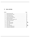
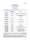
No.: 09 TS-9Rev
December 2, 2009
TO:
Service Locations
FROM:
Technical Support Development
SUBJECT:
MBE 4000 Block-to-Cylinder Head Joint Repair Information
ISSUE
Unnecessary replacement of MBE 4000 cylinder blocks.
REQUIRED ACTION
The attached service information has been developed and released to provide the appropriate
information for diagnosing and repairing MBE 4000 cylinder blocks at the cylinder head to block joint.
Critical areas of the MBE 4000 block can now be repaired instead of replacing the entire block; cylinder
blocks should be repaired using the defined procedures and listed products whenever possible.
Refer to this guide when doing block-to-cylinder head joint repairs.
Note: In addition to the steps outlined in this document, it is necessary to inspect and verify other
components before, during and after the repair to ensure the root cause has been corrected. Refer to the
service manual or TS Letter publications for any operations not covered in this document. Refer to the
guidelines for reusable parts in the service manual, and e-Parts Catalog for other part number criteria not
covered in this document.
CONTACT INFORMATION
Please contact the Detroit Diesel Customer Support Center at 313-592-5800 or email
[email protected] if you have any questions.
Detroit Diesel 13400 Outer Drive, West / Detroit, Michigan 48239-4001
MBE 4000 Cylinder Head to Block
Joint Repair Information
Leak Diagnosis, Cylinder Head and Block Repair
2
CONTENTS
0B
DIAGNOSIS ..............................................................................................................................................4
U
U
Coolant Leaks .......................................................................................................................................4
U
U
Cylinder Liner Inspection .....................................................................................................................5
U
U
Oil Leaks ................................................................................................................................................5
U
U
Counterbore Cracks .............................................................................................................................6
U
U
REPLACEMENT PARTS ........................................................................................................................7
U
U
Cylinder Heads .....................................................................................................................................7
U
U
Cylinder Head Gaskets ........................................................................................................................8
U
U
CYLINDER HEAD AND BLOCK REPAIR RECOMMENDATIONS ...................................................9
U
U
APPENDIX A – REMAN CYLINDER HEAD ACCEPTANCE CRITERIA ........................................10
U
U
APPENDIX B – LINER HEIGHT MEASUREMENT SHEET .............................................................12
U
U
APPENDIX C – REFERENCE MATERIAL .........................................................................................13
U
U
3
light). It is not necessary to change the coolant after
adding the dye.
DIAGNOSIS
1B
Another area that is misdiagnosed for a leaking head
gasket is water (not coolant) seeping from the head
gasket vent hole. Any water over the top of the
engine drains along the block edge towards the back
of the block. As the water passes by the vent hole, a
capillary action sucks the water in and drains the
water out with the change in engine temperature.
This is evident by the rust found near the vent hole
side during teardown inspections. See Figure 2.
Coolant Leaks
8B
It is vital that common practice methods like
pressurizing the coolant are used first to assist in
determining the root origin of coolant leaks. Consider
the length of time in service and prior repair history
as a guideline for where to look for coolant loss.
Typically, the less time a unit has been in service, the
more minor the correction will be while the factors for
coolant leaks from high mileage units may be
corrosion, deterioration, or lack of cooling system
maintenance.
X
X
Vent Hole
The coolant vent line is often misdiagnosed as a
head gasket leak. The coolant vent line is attached
to the center top of each cylinder head and is very
difficult to see behind the EGR cooler and EGR
cooler bracket. However, any leakage from this
coolant vent line will show near the head to block
joint and down the side of the block. See Figure 1.
X
X
Figure 2. Head gasket vent hole witness marks
Engines built after Serial Number 0460896913 have
head gaskets without a vent hole to address this
concern.
Note: Water draining from the truck’s windshield rain
tray may also contribute to this situation. Rain tray
leaks will generally leave a rusty streak since it is
plain water. Head gasket leaks are less rusty in
appearance and will generally appear just wet. Rain
tray leaks are usually location specific on the engine.
Columbia/Century/etc will have rusty streaks between
cylinders 5/6 because the rain tray hole is directly
above that joint between the cylinders. In Sterling car
haulers, the rusty streaks will be up around either
cylinders 1/2 or 2/3 because the engine is set farther
under the cab in that application.
Reference
Freightliner bulletin 60-140 and Sterling bulletin 60-21
for more info on plugging the rain tray hole. See
Figure 3.
Figure 1. Typically any leaks from a properly
maintained coolant system will show up as the coolant
color or white ash if dry
A product that has been very successful in assisting
to find the origin of a coolant leak is tracer dye.
Tracerline® offers Dye-Lite® TP-3900 Fluorescent
Leak Detection Dye for Coolant Systems. Kits are
available with dye and a black light. Information and
local source of this product can be found at
www.tracerline.com. Follow the manufacturer’s
instructions when using this product (1 oz to 6 gal of
coolant, bring the engine to operating temperature,
shutdown the engine, look for dye traces with a black
X
4
X
around and under the liner flange. With the release
of a new liner, o-ring seal, and counterbore cutting
tool, this concern is completely repairable; reference
08 TS-8Rev for complete details on performing this
repair. See Figure 5.
U
U
X
X
Rain Tray Hole (plugged)
Figure 3. Plugging the rain tray drain hole may reduce
water draining on top of engine
X
Cylinder head cracks and cup plug leaks will also
show up as coolant leak witness marks on the sides
of the engine block. Follow the service manual
procedure for pressure checking cylinder heads to
validate the heads if suspect leaking is found. See
Figure 4.
Figure 5. Fretting around cylinder liner from high
mileage
X
Oil Leaks
10B
Oil leaks that occur above the head to block joint may
appear to be problems at this joint, but are really not.
Tracerline® offers Dye-Lite® TP-3400 to assist in
finding the origin of oil leakage. This product is
similar to the product used for coolant, but is specially
formulated for oil.
Follow the manufacturer’s
instruction when using any of these products.
Information and local source of this product can be
found at www.tracerline.com.
Rocker cover gasket leaks are the predominate
source of oil leaks. See Figure 6. This leak will
typically be heavy staining of the sides of the block
and allow dirt to stick. Normal inspection is made
difficult by most of the sealing surfaces being hidden
behind other components. Rocker cover gaskets are
reusable, therefore tightening of the rocker cover hold
down bolts may be the only service required.
X
Figure 4. Leaking cylinder head cup plug
Typically the rear of the cylinder head and the rear
cup plug have been more prone to cracks and leaks
due to being on the exhaust side and exposed to
higher temperatures.
Cylinder Liner Inspection
9B
Units with considerable miles or severe duty cycles
may have liners that have loosened in the bore. This
condition may be evident by erosion and fretting
5
X
Slight Rocker Cover Oil Leak
Figure 6. Rocker cover oil leak
Figure 8. Cracking around counterbore circumference
2B
The Constant Throttle Valve line is another possible
source of oil leaks to consider. The CTV line is
hidden behind the EGR cooler and EGR cooler
brackets, there is a connection on the exhaust face of
each head and will leave oil traces down the side of
the block. See Figure 7.
X
X
Figure 7. Oil traces from leaking CTV line
1B
Counterbore Cracks
Counterbore cracking is primarily caused from
thermal and stress relief of the cylinder block;
however, these circumferential cracks have no
influence on the sealing area and are acceptable for
engine overhaul. See Figure 8. Any erosion of the
counterbore can usually be cleaned up with a light
cutting.
Liner heights are the most important
dimension to be maintained for proper sealing. Shim
thickness must match the cut depth to ensure the
appropriate liner height.
X
X
6
The remanufactured cylinder head has a raised bead
ring around the combustion seal surface area. There
will be a gap if a straight edge is placed over this
deck as well. See Figure 11.
REPLACEMENT PARTS
3B
X
X
Cylinder Heads
12B
Part numbers for the different cylinder heads can be
found in technical service letter 09 TS-11.
U
U
There are three types of fire decks: 1) a very old flat
fire deck with no heat treat in the combustion seal
area and no recess in the coolant and oil grommet
area – see Figure 9, 2) a heat treated original
equipment fire deck cylinder head with flat grommet
sealing areas, and 3) a heat treated original
equipment fire deck cylinder head with recessed
grommet sealing areas - see Figure 10. This style
has four crescent shaped raised sections around the
combustion seal. These raised areas are done by
design and should not be confused or misunderstood
for deck warping.
X
X
X
X
Figure 11. Raised section of combustion sealing area
There are also heads with two cup plugs and heads
with one cup plug and one solid plug. See Figure 12
and Figure 13.
X
X
X
Figure 9. Cylinder head with no recess around oil and
coolant grommet areas
Figure 12. Cylinder head with cup plug
Heat Treat Area
Figure 10. Head with heat treated combustion area and
recessed grommet area
Figure 13. Cylinder head with solid plug
7
X
Cleaning of the cylinder head fire deck should only be
done by hand with flat scotch-brite pads and oil or
diesel fuel to avoid altering the heat treated or
machined surface around the combustion seal area.
Power tool scotch-brite pads are not recommended
as they may remove metal which could distort these
details. Reference 01 TS-38 Letter.
U
U
See Appendix A for Reman cylinder head acceptance
criteria.
Cylinder Head Gaskets
13B
Four different head gaskets have been used over the
last several years: 1) flat grommet without vent, 2) flat
grommet with vent, 3) raised grommet without vent,
and 4) raised grommet with vent. The last design that
is recommended to be used is the closed vent gasket
that matches the flat or recessed grommet hole in the
cylinder head. Figure 14 shows the closed vent
gasket, Figure 15 shows the open vent head gasket,
while Figure 16 shows the flat grommet and Figure
17 shows the raised grommet.
X
X
X
Figure 16. Gasket with flat grommet
X
X
X
X
X
Figure 17. Gasket with raised grommet
Interchangeability:
Figure 14. Closed vent head gasket
Inspection of these parts must happen just prior to
the time of assembly to ensure the proper gasket is
used with the cylinder head. It is possible to have
different heads on the same engine, for example, if a
remanufactured service head was used to replace a
single head on a prior repair.
Note: The head gasket must match the grommet
area of the cylinder head! Cylinder heads machined
with recessed sealing areas require a raised
grommet style head gasket, while a flat cylinder head
requires a flat grommet style head gasket.
Figure 15. Open vent head gasket
8
CYLINDER HEAD AND BLOCK
REPAIR RECOMMENDATIONS
4B
The next step is to stuff shop towels into the push rod
holes such that the towel is below the surface but can
later be removed with needle nose pliers. This will
keep any debris from contamination the cam and
cam followers.
Units with cylinder head to cylinder block leakage
concerns are now repairable. In most cases, there is
no longer any reason to replace engine assemblies.
Note: Remove towels from cylinder block after
surface refinishing is complete.
The sealing areas are: 1) the compression seal
around the liner, 2) the two coolant holes that are
sealed with grommets, and 3) the two oil holes that
are sealed with grommets. See Figure 18.
X
3M Roloc Bristle Discs are recommended to remove
carbon and surface rust. These discs come in three
levels of abrasiveness: green (50 grit), yellow (80
grit), and white (120 grit) for different purposes. See
Figure 20.
X
X
Figure 18. Critical head sealing areas
Figure 20. 3M Roloc Bristle Disc 2", used for cleaning
mating surfaces
These five areas are the most important to maintain
and qualify to ensure a quality repair. The liner
height is set by the counterbore cut and sets the
proper crush for sealing the combustion chamber as
well as the other grommets. For high mileage units,
the recommendation is to set the liner heights to the
lower half of the specification, this will allow for minor
surface imperfection while applying maximum crush
on the grommets. Reference 08 TS-8Rev.
U
Severe areas may require tapping or chipping, but
you must stay away from the grommet sealing areas.
These areas will typically be the cleanest because
they were protected by the grommets and as long as
there is no area higher than the grommet sealing
areas, everything should seal properly.
Pitted surfaces that are not in a sealing or grommet
area should not be a problem, but they do look bad
and if in question or they are in a sealing area there
are epoxy products recommended to repair these
areas. See Figure 21.
U
If the block surface has become eroded, a quality
repair can still be achieved. The recommendation is
to remove the liners and the dowel pins before
attempting to clean the block deck. Using a collet
type dowel puller will make the job easier. See
Figure 19.
X
X
X
X
Figure 19. Collet type dowel puller
9
X
and fine emery cloth, or by draw filing. See Figure
23. Minimum to no metal removal is the goal.
X
X
Figure 21. Repairable block surface using Devcon
Titanium Putty 10760
Figure 23. Draw filing the block deck to obtain a
perfect sealing surface
Devcon® Titanium Putty 10760 with cleaner is a
recommended epoxy for filling in pitting.
Also
®
Belzona 11311 Ceramic R-Metal is considered an
industry standard.
Follow the manufacturer’s
instruction when using these products. It is always
better to use these products sparingly to minimize the
removal of excess material. These epoxies can also
be used to fill-in pitting found on the seat of the
counterbore. The sides of the counterbore have
minimal effect and should not be a concern if pitting
is found there. See Figure 22. Contact information
for the epoxy can be found at www.devcon.com and
www.belzona.com.
X
After prepping the block deck and during the liner
height measurements, you can use the same tools to
qualify the surfaces at the grommet areas. See
Figure 24. The areas around the grommets should
be within 0.012 mm (0.0005”) of the block deck.
Appendix B is a Liner Height Data Sheet.
X
X
X
Figure 24. Measuring cylinder liner protrusion
Remember to check the alignment of the cylinder
heads to each other to avoid exhaust manifold gasket
failure. Use the proper alignment tool to set the
cylinder heads, apply a light torque and recheck to
ensure the heads have not moved.
Figure 22. Sidewall pitting is not critical
After making epoxy repairs to the block surface,
lightly finish the top deck by using a stone, a block
5B
10
APPENDIX A – REMAN CYLINDER HEAD ACCEPTANCE CRITERIA
Small indications around the induction
hardened areas are normal and
ARE ACCEPTABLE.
Small indications in a circular pattern around
the combustion chamber are normal and
ARE ACCEPTABLE.
Indications that are NOT ACCEPTABLE include:
• Any crack that radiates outward from a bolt hole, valve or passage
• Any crack that radiates towards the edge of the head
• Any crank that radiates from the edge of the head
• Any crack between valves, bolt holes or passages
11
09 TS-9Rev
- 12 -
APPENDIX B – LINER HEIGHT MEASUREMENT SHEET
6B
12/2/2009
09 TS-9Rev
- 13 -
12/2/2009
APPENDIX C – REFERENCE MATERIAL
7B
(Dated Material as of 11-25-09)
w
www.ddcsn.com
MBE 4000 Service Manual
Section 1.3 Cylinder Head
Section 1.4 Cylinder Block
MBE 4000 Service Information
Cylinder Block Liner Service Procedure
Cylinder Block Liner Service Procedure
Cylinder Head Bolts Tightening Stages
CONTACT INFORMATION
08 MBE 4000-1 REV (EPA04)
08 MBE 4000-1 REV (EPA07)
07 EPA04 MBE 4000-6
U
U
U
Technical Service Letter
Please contact MBE
the Detroit
Customer
does notDiesel
recommend
the useSupport
of Scotch Center at 313-592-5800 or email
[email protected]
if you
have any questions.
Brite Pads
or Sandpaper
during engine repairs
MBE 4000 Cylinder Head and Gasket Sealing
Area Inspection
01 TS–38
U
05 TS–38
U
MBE 4000 Coolant Leaks
MBE 4000 Cylinder Head and Head Gasket
Information
08 TS–8Rev
U
09 TS–11
U
www
www.3m.com
Roloc Bristle Discs
Surface Conditioning
www.tracerline.com
Hwww.tr
Dye-Lite TP-3900 Fluorescent Leak Detection
Dye-Lite TP-3400 Fluorescent Leak Detection
Coolant
Oil
Hwww.
www.devcon.com
Devcon Titanium Putty #10760
Epoxy Surface Repair
Hwwwwww
www.belzona.com
Belzona 11311 Ceramic R-Metal
Epoxy Surface Repair