1
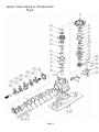
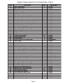
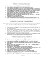
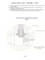
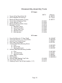
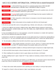
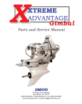
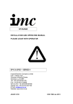
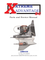
X XTREME ADVANTAGE sc Parts and Service Manual IMCO 510 East Arrow Highway San Dimas, CA 91773 (800) 899-8058 (909) 592-6162 Fax (909) 592-6052 TABLE OF CONTENTS Upper Gearhead-Disassembly, Pinion / Yoke Disassembly, Upper Drive Shaft Disassembly Upper Case Accessories (Drawing) Upper Case Accessories (Parts List) Upper Case Gears & Components (Drawing) Upper Case Gears & Components (Parts List) Pinion / Yoke, Upper Clutch Shaft, Upper Gearhead Reassembly Upper Gearhead Reassembly Continued SC Setup Diagrams SC Work Sheet Backlash Assembly (Drawing) Lower Gear Case Disassembly Lower Gear Case (Drawing) Lower Gear Case (Parts List) Lower Gear Case Assembly Lower Gear Case Assembly Continued, Lower Pinion Height Measurment (Drawing) Dissassembly-Assembly Tools Check Oil Before Running First break in oil change 5-8 hours. Oil is filled to upper drain screw [Fig 1-24] pump oil from bottom drain screw [Fig 3-32] Recommended oil change intervals 20-30 hours. Heavy use or high HP change more often. Serial Number _______________________ Date of Purchase ____________________ Purchased From _____________________ 1/27/10 Rev 8 1 2 3 4 5 6 7 8 9 10 11 12 13 14 15 16 UPPER GEARHEAD – DISASSEMBLY NOTE; The following instructions assume that the drive has been removed from the transom assembly and is shifted to the “neutral” position. The lower unit has also been removed, along with the drive shaft, center socket, and U-joints. The following drawings show the upper drive complete. It is not necessary to remove the gearhead from the mid section. Steps followed by asterisk (**) are required only if inspection indicates component replacement. Brackets following the part name represent the drawing figure # and item #. 1. 2. 3. 4. 5. Remove the rear cover [1-3], shift detent ball & spring [1-13]. Remove 12 point, 3/8-16 screws [1-7], top cap [1-2], and “O” ring [1-21]. Remove 1/4-28 socket cap screws [2-22] from shift shaft. Remove the cooling jet “O” rings [1-22] & cooling jets [1-23].** Remove the upper shift shaft seal disc [1-10]. Shift shaft [2-21], & yoke and cam [2-23]. 6. Remove the shift linkage cotter key, washer, shift linkage assembly [2-19], & shift cable retainer** (Shift linkage is removed from the front of the gearhead) 7. Remove the pinion retainer nut [2-25], retainer nut “O” ring [1-29], & pinion/yoke assembly [30-42]. Note; In steps 8 and 10, be sure to maintain correct assembly position of the upper & lower thrust bearings & races. 8. Remove the upper thrust race [2-7] & upper thrust bearing [2-8]. 9. Remove the clutch shaft [2-17] and gear assembly [2-(9-17)]. 10. Remove the lower thrust bearing [2-8], and lower thrust race [2-7]. 11. Remove the shift shaft bushings [2-20] & shift shaft seals [2-24].** (note position of components if replacement is required). PINION / YOKE DISASSEMBLY** 1. Remove 5/8-18 locknut [2-30] & washer [2-31] 2. Remove the pinion gear with bearings, pinion shim(s) [2-33], pinion shoulder washer [2-40], & pinion seal carrier [2-42] from the yoke (gear end) [2-26]. Note; If the yoke (gear end) seal [2-41] needs replacement it must be removed and installed from the side of the pinion seal carrier which faces the large pinion bearing cup. 3. Remove the large bearing [2-37,38], pinion bearing spacer [2-40], small bearing [2-34,35], & pinion shim(s) [2-33] from the pinion gear. UPPER DRIVE SHAFT DISASSEMBLY 1. Press down on the upper clutch gear [2-13] to release the upper drive shaft retainer keepers [2-9] and remove all components from the clutch shaft [2-17]. Page 1 Upper Case Accessories Fig 1 Page 2 Upper Case Accessories Fig-1 Item 1 1A 2 3 3A 4 4A 5 6 7 8 9 10 11 12 13 14 15 16 17 18 19 20 21 22 23 24 25 26 27 28 29 30 31 32 33 34 35 36 37 38 39 40 41 42 Description Upper Case Black Upper Case Silver Top Cap Rear Cap Black Rear Cap Silver Mid Section Black Mid Section Silver Screw (5/16-18 x 1/2" Button Head) Top Cap Lid Screw (3/8-16 x 1 1/4" S/S 12 Point) Upper Cooling Hose Screw (3/8-16 x 1" S/S Allen Head) Shift Shaft Seal Disc (Upper) Screw (3/8-16 x 2" S/S Allen Head)) "O" Ring (Rear Cap) Detent Kit (Ball Cylinder) Fitting (3/8" NPT to -8JIC S/S) Fitting (1/4" Hose to 1/8" NPT Brass) Lower Cooling Hose Screw (7/16-14 x 2 1/4" S/S 12 Point) Screw (3/8-16 x 3 1/4" S/S Allen Head) (Std & 1") Stud (7/16 x 2") Dowel Pin (1/8" x 7/8" Long) "O" Ring (Upper Cap) "O" Ring (Cooling Jet) Cooling Jet Oil Level Screw Oil Level Screw Washer Spring Kit "O" Ring (Gimbal Shift) "O" Ring (Gimbal Water) "O" Ring (Retainer Nut, Pinion Gear) Screw (5/16-18 x 1/2" Allen Set) (Tower Retainer) "O" Ring (Lower Shaft Seal) "O" Ring (Lower Oil Pressure Seal) "O" Ring (Lower Water Seal) Fitting (1/4" Hose to -4 JIC Brass) Fitting (1/8" NPT to -4 JIC 45° Brass) Lock Nut (7/16-20 S/S Thin Nylock Nut) Washer (7/16" AN S/S Flat Washer Thin) Screw (7/16-14 x 1 1/2" S/S 12 Point) Guide Pads (Port & Starboard) Screw (3/8-16 x 3/4" S/S Hex Head) Washer (3/8" S/S Star Washer Anode Page 3 Qty 1 1 1 1 1 1 1 8 1 2 1 1 1 1 1 1 1 2 1 8 2 1 2 2 1 1 1 1 1 1 1 1 1 1 1 1 8 8 1 1 2 2 1 Part Number 01-1182 01-1184 01-2510 01-1528 01-1528 01-1050 01-1052 08-040705041 01-2071 08-070806091 09-2006 08-060806081 11-1016 08-060806121 11-4015 01-2044 09-2005 09-2004 09-2003 08-070907141 08-060806171 08-130904121 01-2113 11-2157 11-2014 01-2184 01-2504 11-1017 01-2045 11-2139 11-4021 11-2154 08-050705041 11-2132 11-4012 11-2124 09-2002 09-2001 08-090904001 08-160900001 08-070907101 01-2066 08-010806061 08-110800001 01-2067 Upper Case Gears & Components Fig-2 Page 4 Upper Case Gears & Components Fig-2 Item 1 1A 2 3 4 4A 5 6 7 8 9 10 11 12 13 14 15 16 17 18 19 20 21 22 23 24 25 26 26A 27 27A 28 28A 29 29A 30 31 32 33 34 35 36 37 38 39 40 40A 41 41A 42 42A Description Upper Case Black Upper Case Silver Top Cap Roller Bearing (Clutch Shaft-Cap) Mid Section Black Mid Section Silver Tower Race Roller Bearing (Clutch Shaft-Tower) Thrust Race Thrust Bearing Keepers Clutch Shaft Retainer (Thrust Collar) Snap Ring (Clutch Gear Bearing Retainer) Roller Bearing (Internal Gear) SC Clutch Gear (16-19) Thrust Bearing (Clutch Spring) Clutch Spring SC Clutch Cone SC Clutch Shaft SC Tower SC Shift Linkage Assy Shift Shaft Bushing SC Shift Shaft Screw (1/4-28 x 3/4" Socket Cap) Yoke & Cam Seal, Shift Shaft Retainer Nut Yoke Gear End Yoke Gear End HD Cross & Bearing (Cup dia. 1.078) Cross & Bearing HD (Cup dia. 1.219) Center Socket Center Socket HD Yoke Coupler End Yoke Coupler End HD Nut (Yoke Gear End) (5/8-18 Thin Nylock Steel) Washer (Yoke Gear End) SC Pinion Gear Pinion Shim Bearing Cone (Pinion Bearing) Bearing Cup (Pinion Bearing) Pinion Bearing Spacer Bearing Cup (Pinion Bearing) Bearing Cone (Pinion Bearing) Yoke Gear End Shims Pinion Shoulder Washer Pinion Shoulder Washer HD Yoke Gear End Seal Yoke Gear End Seal HD Pinion Seal Carrier Pinion Seal Carrier HD Page 5 Qty 1 1 1 1 1 1 2 1 2 2 2 1 2 2 2 2 2 1 1 1 Kit 2 1 2 1 2 1 1 1 2 2 1 1 1 1 1 1 1 Kit 1 1 1 1 1 Kit 1 1 1 1 1 1 Part Number 01-1182 01-1184 01-2510 10-3017 01-1050 01-1052 10-6018 10-3041 10-5027 01-4027 01-2047 01-2189 01-2057 10-3047 01-4223 10-4020 01-2056 01-2606 01-3599 01-2179 01-2069 10-7019 01-3289 08-060602062 01-2068 11-3030 01-2239 01-3033 01-2085 01-2054 01-2086 01-2052 01-2087 01-2053 01-2088 08-091105002 08-121100002 01-4224 01-2019 10-1021 10-2022 01-2070 10-2024 10-1023 01-2020 01-2167 01-2241 11-3028 11-3029 01-2002 01-2240 PINION / YOKE REASSEMBLY 1. Place the pinion shim(s) [2-33] onto the pinion gear [2-32]. 2. Press the small pinion bearing cone [2-34] onto the pinion gear. 3. Place the small pinion bearing cup [2-35] , pinion bearing spacer [2-40] (flat side against small bearing cup), & large pinion bearing cup [2-37] onto the pinion gear. 4. Press the large pinion bearing cone [2-38] onto the pinion gear making sure that the pinion bearing spacer can move freely, between the bearing cups. 5. Place the pinion seal carrier [2-42] (with seal), pinion shoulder washer [2-40], & yoke (gear end) shim(s) [2-39] onto the yoke (gear end) [2-26]. 6. Assemble the pinion (with bearings), washer (yoke gear end) [2-31], & nut (yoke gear end) [2-30] onto the input yoke. 7. Torque the nut (yoke gear end) to 75 lb/ft. 8. Check for proper pinion bearing pre-load by measuring the rolling torque of the pinion assembly (correct torque is 6 to 10 lb/in.). Re-shim the yoke if required. UPPER CLUTCH SHAFT REASSEMBLY Note; Optimum performance of the upper gearhead requires “setting up” the pinion & clutch gears with IMCO “SC Setup Diagrams” (Fig 3) and “SC Work Sheet” (Fig 4). 1. Place the lower clutch gear [2-13] onto the upper clutch shaft [2-17], allowing it to rest on the thrust collar. 2. Place the lower thrust bearing (clutch spring) [2-14] (silver side “up”), lower clutch spring [2-15], clutch cone [2-16], upper clutch spring [2-15] upper thrust bearing (clutch spring) [2-14] (silver side “down”, upper clutch gear [2-13] and clutch shaft retainer (thrust collar) [2-10] onto the upper clutch shaft. 3. Compress the upper clutch gear and install the keepers [2-9]. Release the upper gear and check that the retainer keepers are seated correctly. UPPER GEARHEAD REASSEMBLY 1. 2. 3. 4. Position the lower clutch gear thrust race [2-7] into the upper gearhead. Place the lower clutch gear thrust bearing [2-8] onto the lower race and “center”. Install the upper drive shaft / gear assembly [2-9 thru 17] into the gearhead. Place the upper clutch gear thrust bearing [2-8] & thrust race [2-7] onto the upper clutch gear. 5. Align the clutch gear timing marks (“+” over “-“, or, “-“ over “+”) with the center of the rear face of the gearhead. 6. Install the yoke / pinion assembly [2-26-42] into the gear head. 7. Place the “O” ring (retainer nut) [1-29] over the yoke, making sure that the “O” ring is fully contained in the outer groove of the pinion seal carrier. 8. Install the pinion retainer nut [2-25] until contact is made. 9. Rotate the yoke and recheck alignment of clutch gear timing marks. 10. Torque the pinion retainer nut to 200 lb/ft. (When using an extension tool, remember to recalculate torque value). 11. Place the yoke & cam [2-23] into the clutch cone groove with the nuts facing down. Page 6 UPPER GEARHEAD REASSEMBLY CONTINUED 11. Insert the shift linkage [2-19] with shift cable retainer into the shift link cavity from the front side of the gearhead. 12. From the rear of the gearhead, place the small hole of the shift arm onto the “pin” of the shift linkage and secure with washer & cotter key. (Be sure that the shift arm is positioned correctly) 13. Install the shift shaft [2-21], align holes in shift shaft with the yoke and cam and the shift arm. 14. Install the two ¼-28 socket cap screws [2-22] and torque to 100 lb/in. 15. Place the cooling jets [1-23] into the gear head. (Rotate to position correctly) 17. Replace the upper shift shaft seal disc [1-10], cooling jet “O” rings [1-22], and “O” ring (upper cap) [1-21]. 18. Attach the top cap [1-2], with bearings, torquing the screws alternately to 20 lb/ft. 19. Attach the rear cap [1-3] including the detent kit [1-13]. Page 7 SC Setup Diagrams Fig-3 Page 8 SC WORK SHEET Fig 4 Serial # UPPER CAP Parallels Cap Deck to Thrust Seat 2.250 Measurement A - Norm 1.994 Total B = Norm 0.256 DECK TO PINION CENTERLINE Deck to Tool Measurement C Less Parallel - Deck to Pinion CL Total + D 1.719 Norm 0.719 Norm 2.6255 1.000 Total Plus 1/2 tool Norm 1.9065 = UPPER THRUST SEAT Deck to Pinion CL Pinion CL to Upper Thrust Seat D Total Norm 2.6255 B - Norm 0.256 E = Norm 2.3695 Norm 0.061 Bearing Thickness - 0.125 Mounting Distance - 2.183 Race Thickness F = LOWER THRUST SEAT Measurement Deck to Lower Thrust Seat Norm 5.994 Parallel - Total = Norm 4.994 D - Norm 2.6255 H = Norm 2.3685 Norm 0.061 Deck to Pinion CL Pinion CL to Lower Thrust Seat G Total 1.000 Bearing Thickness - 0.125 Mounting Distance - 2.183 Race Thickness J = GEAR MEASURMENTS Gear One Measurement K1 Less Parallel - Norm 1.874 1.000 Gear Depth One Total L Norm 0.874 Gear Two Measurement K2 Norm 1.874 Norm 0.874 Less Parallel Gear Depth Two 1.000 Total M = GEAR ASSEMBLY Gear Depth One L Norm 0.874 Gear Depth Two M + Norm 0.874 Race Thickness F + Norm 0.061 Race Thickness J + Norm 0.061 Norm 2.650 2 x Bearing Thickness + Retainer Spacing Measurement N + Gear Assembly Total O = 0.250 4.768 CAP CRUSH Pinion CL to Upper Thrust Seat E + Norm 2.3695 Pinion CL to Lower Thrust Seat H + Norm 2.3695 Upper Thrust Seat to Lower Thrust Seat Total P = Norm 4.739 Gear Assembly O = Norm 4.768 = Norm .020-.030 Cap Crush Total Page 9 Backlash Assembly Fig-5 Page 10 LOWER GEAR CASE – DISASSEMBLY Note; The following instructions assume that the lower unit has already been separated from the upper gearhead. Steps followed by asterisks (**) are required only if inspection indicates component replacement. Brackets following the part name represent the drawing figure # and item #. 1. Bend the tabs of the bearing carrier tab washer [6-31] away from the bearing carrier retainer nut [6-30]. 2. Remove the bearing carrier retainer nut [6-30]. 3. Remove the bearing carrier [6-34]. 4. Remove the prop shaft [6-27]. (The prop shaft bushing [6-26], used only with the 01-8244 & 01-8248 gear sets, may come out with the prop shaft). 5. Remove the bearing carrier “O” ring [6-38], shims [6-39], & thrust washer [6-40]. 6. Remove the vertical shaft flange nut [6-29]. 7. Remove “O” ring [6-13], & alignment spacer [6-14], shims [6-15], & tab washer [6-16]. 8. Remove the vertical shaft [6-2] (with bearings) & pinion gear [6-25]. 9. Remove the prop gear [6-25], (with bearing). (The prop shaft bushing [6-26] may be removed from the gear at this time, if it was not removed in step #4). 10. Remove the lower vertical shaft bearing cup [6-20], & shims [6-21]. 11. Remove the vertical shaft roller bearing [6-28]. ** 12. Remove the upper [6-18], & lower [6-19] bearing cones from the vertical shaft. ** 13. Remove the roller bearing race [6-3] from the vertical shaft. ** 14. Remove the bearing cup [6-36] from the bearing carrier. ** 15. Remove the prop shaft seals [6-35] from the bearing carrier. ** 16. Remove the prop gear bearing cone [6-24] from the prop gear. ** 17. Remove the prop gear bearing cup [6-23], & shims [6-22]. ** 18. Remove the bearing cone [6-37] from the prop shaft. ** 19. Remove the “O” ring [6-6]. “O” ring [6-7], & “O” ring [6-8]. ** Page 11 Lower Gear Case Fig-6 Page 12 Lower Gear Case Fig-6 1 1A 1B 1C 2 2A 2B 2C 3 4 5 6 7 8 9 10 11 12 13 14 15 16 17 18 19 20 21 22 23 24 25 25A 25B 26 27 27A 27B 28 29 30 31 32 33 34 34A 34B 35 35A 35B 35C 36 36A 36B 37 37A 37B 38 39 40 Description Lower Case (-0) Standard Length Lower Case (-1") Shorter Lower Case (-2") Shorter Lower Case (-3") Shorter Vertical Shaft-Standard Length Vertical Shaft-1" Shorter Vertical Shaft-2" Shorter Vertical Shaft 3" Shorter Bearing Race Nut (7/16-20 Nylock S/S Thin) Washer (7/16" AN S/S Thin) "O" Ring (Oil Passage) "O" Ring (Water Passage) "O" Ring (Cooling Water Passage) Pipe Plug - 1/8 NPT S/S Stud (7/16 x 2" S/S) Retainer Ring (Vertical Shaft Coupler) Vertical Shaft Coupler "O" Ring (Alignment Spacer) Alignment Spacer Shim (Vertical Shaft Upper) Tab Washer (Vertical Shaft) Bearing Cup (Vertical Shaft Upper) Bearing Cone (Vertical Shaft Upper) Bearing Cone (Vertical Shaft Lower) Bearing Cup (Vertical Shaft Lower) Shim (Vertical Shaft Lower) Shim (Prop Gear) Bearing Cup (Prop Gear) Bearing Cone (Prop Gear) Prop & Pinion Gear 1:50 Prop & Pinion Gear 1:34 Prop & Pinion Gear 1:25 Bushing - Prop Shaft, -X Prop Shaft, 1" Prop Shaft, 1 1/4" Prop Shaft, 1 7/16" Bearing (Roller) Nut (Pinion Gear) Cover Nut Tab Washer (Bearing Carrier) Drain Screw Drain Screw Sealing Washer Bearing Carrier (1" Prop Shaft) Bearing Carrier (1 1/4" Prop Shaft) Bearing Carrier (1 7/16" Prop Shaft) Seal (Prop Shaft 1") Seal (Prop Shaft 1" Line Cut) Seal (Prop Shaft 1 1/4") Seal (Prop Shaft 1 7/16") Bearing Cup (I" Prop Shaft) Bearing Cup (1 1/4" Prop Shaft) Bearing Cup (1 7/16" Prop Shaft) Bearing Cone (1" Prop Shaft) Bearing Cone (1 1/4" Prop Shaft) Bearing Cone (1 7/16" Prop Shaft) "O" Ring (Bearing Carrier) Shim (Bearing Carrier) Thrust Washer (.109 Thick) Page 13 Qty 1 1 1 1 1 1 1 1 1 2 2 1 1 1 1 2 1 1 1 1 Kit 1 1 1 1 1 Kit Kit 1 1 Set Set Set 1 1 1 1 1 1 1 1 1 1 1 1 1 1 1 2 2 1 1 1 1 1 1 1 Kit 1 Part Number 01-1120 01-1121 01-1122 01-1123 01-3255 01-3256 01-3257 01-3258 10-6005 08-090904001 08-160900001 11-4011 11-2143 11-2014 09-2007 08-130904121 08-121500001 01-2148 11-2228 01-2015 01-2012 01-2043 10-2012 10-1011 10-1010 10-2009 01-2013 01-2014 10-2007 10-1008 01-8240 01-8244 01-8248 01-2178 01-3009 01-3010 01-3570 10-3006 01-2251 01-2065 01-2042 01-2504 11-1017 01-2130 01-2131 01-2575 11-3035 11-3032 11-3033 11-3034 10-2014 10-2016 10-2018 10-1013 10-1015 10-1017 11-2344 01-2011 01-2590 LOWER GEAR CASE - ASSEMBLY Note; Optimum performance of lower gears requires pinion height setup, use “ Lower Pinion Gear Height Measurement” (Fig. 7) sheet to set pinion gear. 1. Install the vertical shaft roller bearing [6-28] into the gear case. 2. Install the vertical shaft lower bearing cup [6-20], & shims [6-21]. 3. Install the lower [6-19], upper [6-18] bearing cones, and roller bearing race [6-3] onto the vertical shaft [6-2]. 4. Install the vertical shaft into the gear case. 5. Install the upper bearing cup [6-17]. Tab washer [6-16], shims [6-15], & alignment spacer [6-14] onto the vertical shaft. 6. Install the vertical shaft clamp plate onto the gear case. (Mercury Part # 43559T) 7. Check the rolling torque of the vertical shaft (optimum 3 to 5 lb/in). 8. Adjust the thickness of the upper shim to obtain the correct rolling torque. 9. Temporarily install the pinion gear [6-25], & flange nut [6-29]. 10. Check the pinion gear height (optimum .025) (see “Lower Pinion Height Measurement” (Fig. 7) 11. If pinion gear height requires correction remove all associated components and adjust the lower bearing shims. Any adjustment here requires that the upper bearing shims be compensated by the same amount. 12. Remove the vertical shaft & pinion. 13. Install the prop gear bearing shims [6-22], & bearing cup [6-23] into the gear case. 14. Install the prop gear bearing cone [6-24] onto the prop gear [6-25]. 15. Install the prop gear with bearing into the gear case. (The prop shaft bushing [6-26], used only with the 01-8244 and 01-8248 gear sets, must be installed into the prop gear at this time). 16. Re-install the vertical shaft components described above, and install the vertical shaft clamp plate. 17. Install the bearing carrier bearing cone [6-37] onto the prop shaft. 18. Install the prop shaft with bearing into the gear case. 19. Install the prop shaft seals [6-35], & bearing carrier bearing cup [6-36] into the bearing carrier [6-34]. 20. Temporarily install the bearing carrier into the gear housing. 21. Install the bearing carrier tab washer [6-31], & retainer nut [6-30], and torque the retainer nut to 150 lb/ft. 22. Rotate the vertical shaft at least 3 turns and check the prop gear backlash (optimum .012 to .015). 23. Adjust the thickness of the prop gear bearing cup shims [6-22] to obtain the correct backlash readings. 24. During final assembly be sure to clean & loctite the vertical shaft flange nut [6-29]. Torque the nut to 100 lb/ft. 25. Temporarily install the bearing carrier thrust washer [6-40], & shims [6-39] prior to prop shaft & bearing carrier installation. 26. Torque the bearing carrier retainer nut to 150 lb/ft. 27. Check overall rolling torque at the vertical shaft (optimum 11 to 17 lb/in). Page 14 LOWER GEAR CASE – ASSEMBLY CONT. 28. Adjust the thickness of the bearing carrier shims [6-39] to obtain the correct rolling torque readings. 29. Upon final assembly be sure to install the bearing carrier “O” ring [6-38] prior to installation of the bearing carrier. 30. After applying final torque of the bearing carrier retainer nut [6-30], bend one tab of the tab washer [6-31] to engage with one of the slots in the retainer nut. Lower Pinion Height Measurement Fig-7 Page 15 Disassembly-Assembly Tools SC Upper IMCO 1. 2. 3. 4. 5. 6. 7. Tower & Cap Race Puller Kit Pinion Retainer Nut Wrench Bearing & Race Installer (Tower) Tower Internal Bearing Puller Tower Removal Tool Bearing & Race Installer (Cap) Backlash Tool Kit A. Backlash Tower B. Indicator Bracket C. Pinion Gear Lock D. Backlash wand E. Dial Indicator Mercury 91-90774 91-17256 91-90773 01-5401 01-5402 01-5403 01-8018 01-5404 01-5405 01-5406 01-5407 01-5408 SC Lower 1. 2. 3. 4. 5. Cover Nut Wrench (1” Prop Shaft) Cover Nut Wrench (1 ¼” Prop Shaft) Lower Pinion Height Gauge Prop Gear Cup Installer Vertical Shaft Roller Bearing Driver A. Pilot B. Driver Rod C. Bearing Remover 6. Vertical Shaft Roller Bearing Installer A. Pilot B. Threaded Rod C. Bearing Installer 7. Clamp Plate 8. Dial Indicator 9. Vertical Shaft Bearing Cup Puller 10. Prop Gear Cup Puller 11. Bearing Carrier Cup & Seal Installer (1 ¼”) Page 16 91-61069T 91-840393 91-42840 91-31106 91-813653 91-37323 91-63638T 91-813653 91-31229 91-89867 91-43559T 91-58222A1 01-5409 01-5410 01-5411