1
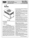
PERFORMANCE™ 13 50XP
SINGLE-PACKAGED ELECTRIC COOLING UNITS
WITH PURON® (R-410A) REFRIGERANT
2 to 5 Nominal Tons
Product Data
Single-Packaged Products with
Energy-Saving Features and Puron®
refrigerant.
• Low Sound Levels
• 13 SEER
• Variable Speed Blower-Standard
• Factory Installed TXV
Features/Benefits
One-piece cooling unit with optional
electric heater, low installation cost,
dependable performance and easy
maintenance.
Efficient operation
UNIT 50XP
High-efficiency design with a SEER
(Seasonal Energy Efficiency Ratio)
of 13.0.
Puron® Environmentally Sound
Refrigerant is Carrier’s unique
refrigerant designed to help protect the
environment. Puron is an HFC
refrigerant which does not contain
chlorine that can harm the ozone layer.
The most important advantage of
Puron refrigerant is that it has not been
banned in future air conditioning
systems as the traditional refrigerant
R-22 has been. Puron refrigerant is in
service in thousands of systems
proving highly reliable,
environmentally sound performance.
IdealHumidity™ Technology
featuring Thermidistat control and
Variable Speed Blower motor that
provides greater comfort, humidity
control, and energy efficiency. You can
expect up to 30 times better
dehumidification; economical constant
fan for less than $50 a year, which
provides improved indoor air quality
and more even temperatures from room
to room; and reduced indoor noise due
to lower air velocity. In addition, you’ll
realize improved installation flexibility
with 3 different airflow choices for best
overall comfort.
Easy Installation
Factory-assembled package is a
compact, fully self-contained, electric
50XP
cooling unit that is pre-wired, prepiped, and pre-charged for minimum
installation expense. 50XP units are
available in a variety of standard
cooling sizes with voltage options to
meet residential and light commercial
requirements. Units are light weight,
and install easily on a rooftop or at
ground-level. The hightech, composite
base pan eliminates rust problems
associated with ground level
applications.
Durable, dependable
components
Scroll Compressors are designed for
high efficiency. Each compressor is
hermetically sealed against
contamination to help promote longer
life and dependable operation.
Vibration isolation provides quiet
operation. Compressors have internal
high-pressure and overcurrent
protection.
Convertible duct configuration
Unit is designed for easy use in either
downflow or horizontal applications.
Each unit is easily converted from
horizontal to downflow.
Direct-drive variable speed blower
motor is standard on all 50XP models.
Direct-drive, PSC condenser-fan
motors are designed to help reduce
energy consumption and provide for
cooling operation down to 55°F outdoor
temperature. Motormaster® II low
ambient kit is available as a fieldinstalled accessory.
Corporate thermostats include the
Time Guard® II anti-short cycle
protection circuitry. If a non-Corporate
thermostat without anti-short cycle
protection, is used the Time Guard II
field installed anti-short cycle kit is
recommended.
Refrigerant system is designed to
provide dependability. Liquid refrigerant
filter driers are used to promote clean,
unrestricted operation. Each unit leaves
the factory with a full Puron® refrigerant
charge. Refrigerant service connections
are standard on the suction and discharge
lines for checking operating pressures.
Thermostatic Expansion Valve – A
hard shutoff, balance port TXV
maintains a constant superheat at the
evaporator exit (cooling cycle) resulting
in higher overall system efficiency.
Evaporator and condenser coils are
computer-designed for optimum heat
transfer and cooling efficiency. The
evaporator coil is fabricated from
copper tube and aluminum fins and is
located inside the unit for protection
against damage. The condenser coil is
internally mounted on the top tier of the
unit. Copper fin coils and pre-coated fin
coils are available from the factory by
special order. These coils are
recommended in applications where
aluminum fins are likely to be damaged
due to corrosion. They are ideal for
seacoast applications.
High and Low Pressure Switches give
added safety and reliability to the
compressor.
Low sound ratings ensure a quiet
indoor and outdoor environment with
sound ratings as low as 72 dB.
(See page 3.)
Easy to service cabinets provide easy
single-panel accessibility to serviceable
components during maintenance and
installation. The basepan with
integrated drain pan provides easy
ground level installation with or without
a mounting pad. Convenient handholds
are provided to manipulate the unit on
the jobsite. A nesting feature ensures a
positive basepan to roof curb seal when
the unit is roof mounted. A convenient
3/4-in. wide perimeter flange makes
frame mounting on a rooftop easy.
Louvered Grille provides hail and
vandalism protection for the coil.
Downflow operation is easily provided
in the field to allow vertical ductwork
connections. The basepan utilizes
knockout style seals on the bottom
openings to ensure a positive seal in the
horizontal airflow mode.
Cabinets are constructed of heavyduty, phosphated, zinc-coated
prepainted steel capable of
withstanding 500 hours of salt spray.
Interior surfaces of the evaporator and
electric heater compartments are
insulated with cleanable semi-rigid
insulation board, which keeps the
conditioned air from being affected by
the outdoor ambient temperature and
provides improved indoor air quality.
(Conforms to American Society of
Heating, Refrigeration and Air
Conditioning Engineers No. 62P.) The
sloped drain pan minimizes standing
water in the drain, which is provided
with an external drain.
Standard metal duct covers with
insulation come with the unit and cover
the horizontal duct openings. These can
be left in place if the unit is converted to
downflow.
Table of contents
Page
Features/Benefits. . . . . . . . . . . . . . . . . . . . . . . . . . . . . . . . . . . . . . . . . . . . . . . . . . . . . . . . . . . . . . . . . . . . . . . . . . . . . . . . . . . . . . . . 1,2
Model Number Nomenclature . . . . . . . . . . . . . . . . . . . . . . . . . . . . . . . . . . . . . . . . . . . . . . . . . . . . . . . . . . . . . . . . . . . . . . . . . . . . . . .3
ARI Capacities . . . . . . . . . . . . . . . . . . . . . . . . . . . . . . . . . . . . . . . . . . . . . . . . . . . . . . . . . . . . . . . . . . . . . . . . . . . . . . . . . . . . . . . . . . .3
Physical Data . . . . . . . . . . . . . . . . . . . . . . . . . . . . . . . . . . . . . . . . . . . . . . . . . . . . . . . . . . . . . . . . . . . . . . . . . . . . . . . . . . . . . . . . . . . .4
Options and Accessories . . . . . . . . . . . . . . . . . . . . . . . . . . . . . . . . . . . . . . . . . . . . . . . . . . . . . . . . . . . . . . . . . . . . . . . . . . . . . . . . . . 5,6
Base Unit Dimensions. . . . . . . . . . . . . . . . . . . . . . . . . . . . . . . . . . . . . . . . . . . . . . . . . . . . . . . . . . . . . . . . . . . . . . . . . . . . . . . . . . . . 7,8
Accessory Dimensions . . . . . . . . . . . . . . . . . . . . . . . . . . . . . . . . . . . . . . . . . . . . . . . . . . . . . . . . . . . . . . . . . . . . . . . . . . . . . . . . . . . . .9
Selection Procedure . . . . . . . . . . . . . . . . . . . . . . . . . . . . . . . . . . . . . . . . . . . . . . . . . . . . . . . . . . . . . . . . . . . . . . . . . . . . . . . . . . . . . .10
Performance Data . . . . . . . . . . . . . . . . . . . . . . . . . . . . . . . . . . . . . . . . . . . . . . . . . . . . . . . . . . . . . . . . . . . . . . . . . . . . . . . . . . . . . 11-15
Typical Piping and Wiring . . . . . . . . . . . . . . . . . . . . . . . . . . . . . . . . . . . . . . . . . . . . . . . . . . . . . . . . . . . . . . . . . . . . . . . . . . . . . . . . .16
Application Data . . . . . . . . . . . . . . . . . . . . . . . . . . . . . . . . . . . . . . . . . . . . . . . . . . . . . . . . . . . . . . . . . . . . . . . . . . . . . . . . . . . . . . . . .17
Electrical Data. . . . . . . . . . . . . . . . . . . . . . . . . . . . . . . . . . . . . . . . . . . . . . . . . . . . . . . . . . . . . . . . . . . . . . . . . . . . . . . . . . . . . . . .18, 19
Typical Wiring Schematics. . . . . . . . . . . . . . . . . . . . . . . . . . . . . . . . . . . . . . . . . . . . . . . . . . . . . . . . . . . . . . . . . . . . . . . . . . . . . .20, 21
Controls. . . . . . . . . . . . . . . . . . . . . . . . . . . . . . . . . . . . . . . . . . . . . . . . . . . . . . . . . . . . . . . . . . . . . . . . . . . . . . . . . . . . . . . . . . . . . . . .22
Guide Specifications . . . . . . . . . . . . . . . . . . . . . . . . . . . . . . . . . . . . . . . . . . . . . . . . . . . . . . . . . . . . . . . . . . . . . . . . . . . . . . . . . . .23, 24
2
Model number nomenclature
50XP
024
3
—
Options
Nominal Cooling Capacity
024 – 2 ton
030 – 2.5 ton
036 – 3 ton
042 – 3.5 ton
048 – 4 ton
060 – 5 ton
50XP
BT – AL evap, vinyl condens
CC – AL evap, CU condens
Options
CU –
– Wire
CU Grille
evap & condens
(None)
– BaseGrille
unit with tin plated indoor coil
AD TP
– Louvered
hairpins
BT – Wire Grille
and Vinyl-Coated Condenser
TVCoil
– Fin
TP with vinyl coating on outdoor coil
TC
– TP with
ALand
indoor
coil & CU/CU
XT –
Louvered
Grille
Vinyl-Coated
Con-outdenserdoor
Coilcoil
Fin
CC – Wire Grille, AL Evaporator and CU/CU
Only
used if ordering
an option
Condenser
Coil
AC – Louvered Grille, AL Evaporator and CU/
CU con
Model Number
50XP – Single
Packaged-Electric
Cooling
V-Ph-Hz
3 – 208/230-1-60
5 – 208/230-3-60
AL — Aluminum
CU — Copper
ARI* capacities
COOLING CAPACITIES AND EFFICIENCIES
UNIT
50XP
NOMINAL
TONS
STANDARD
CFM
NET COOLING
CAPACITIES
(Btuh)
EER@A**
SEER†
SOUND
RATINGS‡
(dB)
024
030
036
042
048
060
2
2-1/2
3
3-1/2
4
5
800
1000
1100
1400
1450
1710
24,000
28,800
36,000
41,000
45,000
57,000
11.0
11.0
11.0
11.0
11.0
11.0
13.0
13.0
13.0
13.0
13.0
13.0
72
72
72
72
78
78
LEGEND
dB
— Sound Levels (decibels)
db
— Dry Bulb
SEER — Seasonal Energy Efficiency Ratio
wb
— Wet Bulb
* Air Conditioning & Refrigeration Institute.
** “A” Conditions- 80°F indoor db/67°F indoor wb & 95°F outdoor db.
† Rated in accordance with U.S. Government DOE Department of
Energy) test procedures and/or ARI Standard 210/240-94.
‡ Tested in accordance with ARI Standard 270-95 (not listed in ARI).
NOTES:
1. Ratings are net values, reflecting the effects of circulating fan heat.
Ratings are based on:
Cooling Standard: 80°F db, 67°F wb indoor entering-air temperature and 95°F db outdoor entering-air temperature.
2. Before purchasing this appliance, read important energy cost and
efficiency information available from your retailer.
3
OUTDOOR SOUND: OCTAVE BAND DATA—DECIBELS (Lw(A))
50XP
024
58.8
63.5
67.2
66.9
63.7
58.3
50.0
030
58.8
63.5
67.2
66.9
63.7
58.3
50.0
036
60.7
63.3
66.8
66.5
64.2
60.3
53.0
042
56.7
62.8
67.8
67.4
63.7
57.7
50.8
048
62.4
69.9
71.3
73.4
70.0
66.3
60.1
060
63.5
67.6
71.8
75.5
71.0
68.1
59.9
Physical data
UNIT SIZE 50XP
024
030
036
042
048
NOMINAL CAPACITY (ton)
2
2-1/2
3
3-1/2
4
5
OPERATING WEIGHT (lb)
343
343
366
433
456
492
COMPRESSOR
060
Scroll
REFRIGERANT (R-410A)
Quantity (lb)
7.3
8.0
9.5
10.7
11.25
13.2
REFRIGERANT METERING DEVICE
(Indoor)
TXV
TXV
TXV
TXV
TXV
TXV
CONDENSER COIL
Rows—Fins/in.
Face Area (sq ft)
2—21
11.95
2—21
12.0
2—21
13.6
2—21
15.4
2—21
17.4
2—21
19.3
CONDENSER FAN
Nominal Cfm
Diameter (in.)
Motor Hp (Rpm)
2350
22
1/8 (825)
2700
22
1/8 (825)
2350
22
1/8 (825)
2800
22
1/8 (825)
3300
22
1/4 (1100)
3300
22
1/4 (1100)
3—15
3.7
3—15
3.7
4—15
3.7
3—15
4.7
4—15
4.7
4—17
5.7
800
10 x 10
1/2
1000
10 x 10
1/2
1100
11 x 10
3/4
1400
11 x 10
3/4
1400
11 x 10
3/4
1750
11 x 10
1.0
24 x 30 x 1
24 x 30 x 1
24 x 30 x 1
EVAPORATOR COIL
Rows—Fins/in.
Face Area (sq ft)
EVAPORATOR BLOWER
Nominal Airflow (Cfm)
Size (in.)
Motor (Hp)
HIGH-PRESSURE SWITCH (psig)
Cutout
Reset (Auto.)
610 ± 15
420 ± 25
LOSS-OF-CHARGE/LOW-PRESSURE
SWITCH
(Liquid Line) (psig)
Cutout
Reset (Auto.)
20 ± 5
45 ± 10
RETURN-AIR FILTERS (in.)*
Throwaway
20 x 20 x 1
20 x 20 x 1
20 x 24 x 1
5
4
3
UNIT
AR
A
AIR
CO
Y
NING
ITIO
ND
A2
T
IFIED O ARI A
RT
S
C
CE
EQ
RI
YING WITH
PL
OM
MANUFACTUR
ER
* Required filter sizes shown are based on the larger of the ARI (Air Conditioning & Refrigeration Institute) rated
cooling airflow or the heating airflow velocity of 300 ft/min for throwaway type or 450 ft/min for high-capacity
type. Air filter pressure drop for non-standard filters must not exceed 0.08 in. wg.
2
50XP
MODEL NO.
Frequency (Hz)
125
250
500
1000
2000
4000
8000
UIP M E NT
STA
NDARD
21
0
Options and accessories
Factory-installed options
Coil options include Tin-Plated* indoor hairpins, copper/
copper and vinyl-coated construction for refrigerant coils.
Units are shipped standard with copper tube/aluminum fin
construction. See model number nomenclature for coil
options.
*Tin-Plated indoor coils are built with special hairpins
that are designed to resist both general pitting corrosion
and excessive indoor corrosion (Formicary Corrosion).
Economizer with Solid-State Controls and Barometric
Relief Dampers
Manual Air Damper (25% open)
Electric Heaters
Filter Rack
Flat Roof Curbs (8-in. and 14-in.)
Square-to-Round Duct Transition Kit
Thermidistat™
Thermostats
Crankcase Heater
Rigging Kit
Low Ambient Kit (Motormaster® II Control)
Solid-State Time Guard® II Device
Lifting Kit
Compressor Hard Start Kit
Economizer with solid-state controls and barometric
relief dampers includes filter racks and provide outdoor air
during cooling and reduce compressor operation.
Manual outside air damper includes hood and filter rack
with adjustable damper blade for up to 25% outdoor air.
Electric heaters provide heat in the unit when required.
Each package has a heater module that slides into the
controls compartment. Heater sizes range from 5 to 20 kW.
The electric heater design allows the use of a single-point
ELECTRIC HEATERS
USED WITH SIZES
024
030
036
042
ELECTRIC HEATERS (208/230 — SINGLE PHASE — 60 Hz)
X
X
X
X
X
X
X
X
X
X
X
X
X
X
X
X
ELECTRIC HEATERS (208/230 — 3 PHASE — 60 Hz)
X
X
X
X
X
X
X
X
X
ODS CATALOG
ORDERING NO.
NOMINAL CAPACITY
(kW)
048
060
CPHEATER052A00
CPHEATER069A00
CPHEATER065A00
CPHEATER051A00
CPHEATER053A00
5.0
7.5
10.0
15.0
20.0
X
X
X
X
X
X
X
X
X
X
CPHEATER055A00
CPHEATER056A00
CPHEATER057A00
CPHEATER059A00
5.0
10.0
15.0
20.0
X
X
X
X
X
X
X
X
LEGEND
ODS — Order Distribution System
NOTE: Electric heaters are rated at 240 v. Refer to Multiplication Factors table for other voltages.
MINIMUM AIRFLOW FOR RELIABLE ELECTRIC HEATER OPERATION
UNIT
AIRFLOW
024
750
030
750
036
1250
042
1205
048
1500
060
1800
5
50XP
Field-installed accessories
power supply for the entire unit, resulting in lower installed
costs.
Flat roof curbs in both 8 in. and 14 in. sizes are available
for roof mounted applications.
Square-to-round duct transition kit enables 024-048 size
units to be fitted to 14 in. round ductwork.
Thermidistat Control coupled with the system’s variable
speed indoor blower delivers Carrier’s patented
IdealHumidity™ Technology that allows for even greater
humidity control. Along with more precisely controlling
temperature and humidity, the Thermidistat offers full
seven-day programmability allowing you to further
customize your comfort and energy savings.
Thermostats provide control for the system heating and
cooling functions. Thermostat models are available in both
programmable and non-programmable versions.
Lifting kit, including 4 metal brackets that are available to
assist in lifting this product onto a roof application.
Crankcase heater provides anti-floodback protection for
low-load cooling applications.
Low-ambient kit (Motormaster II control) allows the
use of mechanical cooling down to outdoor temperatures as
low as 0°F.
Solid-state Time Guard II device provides short-cycling
protection for the compressor. Not required with corporate
electronic thermostats.
Filter rack features easy installation, serviceability, and
high-filtering performance for vertical or horizontal
applications.
Compressor Hard start kit assists compressor start-up by
providing additional starting torque on single phase units
and prolongs compressor motor life.
50XP
ECONOMIZER
FILTER RACK
MANUAL OUTSIDE AIR DAMPER
REPLACEMENT
PANEL
MANUAL OUTSIDE
AIR HOOD
DAMPER
BLADE
7
6
Base unit dimensions—50XP024-036
50XP
UNIT
ELECTRICAL
CHARACTERISTICS
50XP024
208/230-1-60
lb
kg
UNIT HEIGHT
in. [mm]
“A”
343
156
39.02 [991.1]
UNIT WEIGHT
CENTER OF GRAVITY
in. [mm]
X
Y
Z
20 [508]
19.3 [489]
17.6 [447]
50XP030
208/230-1-60
343
156
39.02 [991.1]
20 [508]
19.3 [489]
17.6 [447]
50XP036
208/230-1-60, 208/230-3-60
366
166
41.02 [1041.9]
20 [508]
14 [355.6]
13 [330.2]
50XP 024-036 Dimensions
7
50XP
Base unit dimensions—50XP042-060
8
kg
X
Y
Z
197
42.98 [1091.7]
21 [533.4]
20.5 [520.2]
16.6 [421.6]
456
207
44.98 [1142.5]
19.5 [495.3]
17.6 [447.6]
18.0 [457.2]
492
223
46.98 [1193.3]
21 [533.4]
20 [508]
17.6 [447.0]
ELECTRICAL
CHARACTERISTICS
lb
50XP042
208/230-1-60, 208/230-3-60
433
50XP048
208/230-1-60, 208/230-3-60
50XP060
208/230-1-60, 208/230-3-60
50XP 042-060 Dimensions
CENTER OF GRAVITY
in. [mm]
UNIT HEIGHT
in. [mm]
“A”
UNIT WEIGHT
UNIT
Accessory dimensions
UNIT SIZE
A
in. [mm]
ODS CATALOG NUMBER
50XP024-036
50XP042-060
B
in. [mm]
C
in. [mm]
D
in. [mm]
CPRFCURB006A00
8 [203]
11 [279]
16-1/2 [419]
28-3/4 [730]
CPRFCURB007A00
14 [356]
11 [279]
16-1/2 [419]
28-3/4 [730]
CPRFCURB008A00
8 [203]
16-3/16 [411]
17-3/8 [441]
40-1/4 [1022]
CPRFCURB009A00
14 [356]
16-3/16 [411]
17-3/8 [441]
40-1/4 [1022]
HVAC unit
base
50XP
NOTES:
1. Roof curb must be set up for unit being installed.
2. Seal strip must be applied, as required, to unit being installed.
3. Dimensions in [ ] are in millimeters.
4. Roof curb is made of 16-gage steel.
5. Table lists only the dimensions, per part number, that have changed.
6. Attach ductwork to curb (flanges of duct rest on curb).
7. Insulated panels: 1-in. thick fiberglass 1 lb density.
8. Dimensions are in inches.
9. When unit mounting screw is used (see Note A), a retainer bracket must be used as well. This bracket must also be used when required by code
for hurricane or seismic conditions. This bracket is available through Micrometl.
HVAC unit
base
Screw
(NOTE A)
Screw
(NOTE A)
Gasketing
inner flange*
*Gasketing
outer flange
Gasketing
inner flange*
*Gasketing
outer flange
Wood nailer*
Flashing field
supplied
Wood nailer*
Flashing field
supplied
Roofcurb*
Insulation (field
supplied)
Roofing material
field supplied
Insulation (field
supplied)
Roofing material
field supplied
Duct work
field supplied
Cant strip
field supplied
Roofcurb*
Cant strip
field supplied
Duct work
field supplied
Roof
Roof
*Provided with roofcurb
*Provided with roofcurb
Roof Curb for Small Cabinet
Roof Curb for Large Cabinet
Note A: When unit mounting screw is used,
retainer bracket must also be used.
Note A: When unit mounting screw is used,
retainer bracket must also be used.
Supply opening
(B x C)
B Typ.
44 5/16"
(1125.5mm)
D
C Typ.
R/A
A
Short
Support
Insulated
deck pan
S/A
Gasket around
duct
Insulated
deck pan
Gasket around
outer edge
Long
Support
Return opening
(B X C)
C00076
9
50XP Corner weights (In Pounds)
1
2
50XP
y
4
3
x
Small Base
Large Base
Model 50XP
Corner Weight #1
024
69
030
036
042
048
060
69
74
87
92
99
Corner Weight #2
53
53
57
67
71
77
Corner Weight #3
83
83
88
104
110
119
Corner Weight #4
138
138
147
174
183
198
Total Weight
343
343
366
433
456
492
Selection Procedure
I Determine cooling and heating requirements at design
conditions:
Given:
Required Cooling Capacity (TC) . . . . . . . . . . 34,500 Btuh
Sensible Heat Capacity (SHC). . . . . . . . . . . . 26,000 Btuh
Required Heating Capacity . . . . . . . . . . . . . . 15,000 Btuh
Condenser Entering Air Temperature . . . . . . . . . . . . 95°F
Indoor-Air Temperature. . . . . . . . . . . 80°F edb, 67°F ewb
Evaporator Air Quantity . . . . . . . . . . . . . . . . . . 1200 cfm
External Static Pressure . . . . . . . . . . . . . . . . . . . 0.2 in. wg
Electrical Characteristics . . . . . . . . . . . . . . . . . . .230-1-60
II Select unit based on required cooling capacity.
Enter Cooling Capacities table at condenser entering
temperature of 95°F. The 036 unit at 1225 cfm and 67°F
ewb (entering wet bulb) will provide a total capacity of
36,500 Btuh and a SHC of 27,600 Btuh. Calculate SHC
correction, if required, using Note 4 under Cooling
Capacities tables.
III Select electric heat.
The required heating capacity is 15,000 Btuh (given).
Determine the electric heat capacity in kW.
15,000 Btuh
= 4.4 kW of heat required
3414 Btuh/kW
Enter the Electric Heater Packages table for 208/240,
single-phase, 036 unit. The 5-kW heater at 240v most
10
closely satisfies the heating required. To calculate kW at
208v, multiply the heater kW by multiplication factor 0.75
found in the Wattage Multiplication Factors table.
5 kW x 0.75 = 3.75 kW
3.75 kW x 3414 Btuh/kW = 12,802.50 Btuh
IV Determine fan speed and power requirements at design
conditions.
Before entering the air delivery tables, calculate the total
static pressure required. From the given, Filter Pressure
Drop table, and the Accessory Electric Heat Pressure Drop
table, find:
Wet coil pressure drop
0.032 in. wg
External static pressure
0.200 in. wg
Filter
0.130 in. wg
Total static pressure
0.362 in. wg
Enter the table for Dry Coil Air Delivery — At 0.362 in. wg
external static pressure and NOM speed pin selection, the
motor delivers 1235 cfm.
V Select unit that corresponds to power source available.
The Electrical Data table shows that the unit is designed to
operate at 208/230-1-60.
Performance data-Standard ECM Indoor Motor
COOLING CAPACITIES
50XP024 COOLING PERFORMANCE TABLE
Temp (F)
Outdoor Air
Entering
Condenser
75
85
105
115
125
900/0.032
1000/0.04
Evaporator Air — Ewb (F)
62
63*
67
72
62
63*
67
72
62
63*
67
72
24.0
21.9
1.7
22.9
21.4
1.9
21.8
20.8
2.2
20.5
20.2
2.4
19.2
19.4
2.7
17.8
18.5
2.9
24.5
21.3
1.7
23.3
20.7
1.9
22.2
20.2
2.2
20.9
19.5
2.4
19.5
18.8
2.7
18.0
18.1
2.9
26.5
18.7
1.8
25.3
18.1
2.0
24.0
17.6
2.2
22.6
16.9
2.4
21.1
16.3
2.7
19.4
15.5
3.0
29.1
15.4
1.8
27.9
14.9
2.0
26.5
14.3
2.2
25.0
13.7
2.4
23.3
13.0
2.7
21.4
12.3
3.0
24.6
23.5
1.8
23.5
22.9
2.0
22.3
22.3
2.2
21.0
21.6
2.4
19.8
20.6
2.7
18.5
19.2
3.0
25.1
22.8
1.8
23.9
22.2
2.0
22.6
21.6
2.2
21.3
20.9
2.4
19.9
20.2
2.7
18.5
19.2
3.0
27.1
19.8
1.8
25.8
19.2
2.0
24.5
18.7
2.2
23.0
18.0
2.5
21.5
17.3
2.7
19.5
16.5
3.0
29.8
16.1
1.8
28.5
15.6
2.0
27.0
15.0
2.2
25.4
14.3
2.5
23.7
13.7
2.7
21.7
12.9
3.0
25.1
25.0
1.8
23.9
24.3
2.0
22.7
23.6
2.2
21.6
22.5
2.5
20.7
21.5
2.7
19.0
19.8
3.0
25.5
24.2
1.8
24.3
23.6
2.0
23.0
22.9
2.2
21.7
22.2
2.5
20.4
21.2
2.7
19.0
19.7
3.0
27.4
20.8
1.8
26.2
20.3
2.1
24.8
19.7
2.3
23.3
19.0
2.5
21.7
18.3
2.8
19.9
17.6
3.1
30.4
16.7
1.9
28.9
16.2
2.1
27.4
15.6
2.3
25.7
14.9
2.5
23.6
14.1
2.8
21.9
13.5
3.1
50XP
95
TC
SHC
kW
TC
SHC
kW
TC
SHC
kW
TC
SHC
kW
TC
SHC
kW
TC
SHC
kW
Evaporator Air—CFM/BF
800/0.026
50XP030 COOLING PERFORMANCE TABLE
Temp (F)
Outdoor Air
Entering
Condenser
75
85
95
105
115
125
TC
SHC
kW
TC
SHC
kW
TC
SHC
kW
TC
SHC
kW
TC
SHC
kW
TC
SHC
kW
Evaporator Air—CFM/BF
875/0.06
1000/0.07
1125/0.08
Evaporator Air — Ewb (F)
62
63*
67
72
62
63*
67
72
62
63*
67
72
27.9
24.1
2.1
26.9
23.8
2.3
25.6
23.1
2.6
24.3
22.4
2.9
22.8
21.7
3.2
21.4
20.7
3.5
28.6
20.0
2.1
27.5
19.5
2.3
26.2
19.1
2.6
24.7
18.6
2.9
23.2
18.0
3.2
21.4
17.3
3.5
30.7
20.6
2.1
29.5
20.3
2.4
28.2
19.9
2.6
26.6
19.3
2.9
24.9
18.8
3.2
24.9
18.8
3.2
33.6
16.8
2.1
32.3
16.4
2.4
30.8
16.0
2.6
29.2
15.4
2.9
27.3
14.8
3.2
27.3
14.8
3.2
28.8
26.0
2.1
27.6
25.6
2.3
26.3
24.7
2.6
25.1
23.8
2.9
23.8
22.3
3.2
23.8
22.3
3.2
29.4
21.2
2.1
28.1
20.8
2.4
26.8
20.5
2.6
25.3
19.9
2.9
23.6
19.3
3.2
23.6
19.3
3.2
31.6
22.1
2.1
30.2
21.7
2.4
28.8
21.3
2.6
27.2
20.8
2.9
25.3
20.2
3.2
25.3
20.2
3.2
34.5
17.8
2.2
33.1
17.4
2.4
31.5
16.9
2.6
29.7
16.3
2.9
27.7
15.7
3.2
27.7
15.7
3.2
29.3
27.0
2.1
28.3
26.5
2.4
27.0
26.2
2.6
25.9
24.4
2.9
24.5
23.7
3.2
24.5
23.7
3.2
30.0
22.6
2.1
28.7
22.1
2.4
27.3
21.7
2.6
25.7
21.1
2.9
24.0
20.5
3.2
24.0
20.5
3.2
32.2
23.5
2.1
30.8
23.1
2.4
29.3
22.6
2.6
27.5
22.1
2.9
25.7
21.5
3.2
25.7
21.5
3.2
35.2
18.7
2.2
33.7
18.3
2.4
32.0
17.8
2.6
30.1
17.2
2.9
28.1
16.6
3.2
28.1
16.6
3.2
See Legend and Notes on page 13.
11
Performance data (cont)-Standard ECM Indoor Motor
COOLING CAPACITIES
50XP036 COOLING PERFORMANCE TABLE
Temp (F)
Outdoor Air
Entering
Condenser
75
50XP
85
95
105
115
125
TC
SHC
kW
TC
SHC
kW
TC
SHC
kW
TC
SHC
kW
TC
SHC
kW
TC
SHC
kW
Evaporator Air—CFM/BF
1100/0.06
1225/0.07
1400/0.08
Evaporator Air — Ewb (F)
62
36.2
33.2
2.7
34.6
32.4
2.9
33.0
31.6
3.2
31.3
30.6
3.6
29.6
29.3
4.0
27.8
27.5
4.4
63*
36.8
26.7
2.7
35.1
26.0
2.9
33.4
25.3
3.2
31.5
24.5
3.6
29.4
23.7
4.0
27.2
22.8
4.3
67
39.7
27.8
2.7
37.9
27.1
3.0
36.0
26.4
3.3
34.0
25.6
3.6
31.8
24.8
4.0
29.4
23.9
4.4
72
43.8
22.3
2.7
41.8
21.6
3.0
39.7
20.9
3.3
37.5
20.1
3.6
35.0
19.3
4.0
32.4
18.4
4.4
62
36.9
34.7
2.7
35.3
34.0
3.0
33.7
32.9
3.3
32.1
31.5
3.6
30.4
30.0
4.0
28.4
28.2
4.4
63*
37.4
27.9
2.7
35.6
27.1
3.0
33.8
26.4
3.3
31.9
25.7
3.6
29.8
24.8
4.0
27.5
23.8
4.4
67
40.3
29.0
2.7
38.4
28.3
3.0
36.5
27.6
3.3
34.3
26.8
3.7
32.1
26.0
4.0
29.7
25.0
4.4
72
44.4
23.1
2.8
42.4
22.4
3.0
40.2
21.7
3.4
37.9
20.9
3.7
35.4
20.0
4.0
32.7
19.1
4.4
62
37.9
36.9
2.8
36.4
35.6
3.1
34.8
34.4
3.4
33.1
32.8
3.8
31.3
31.0
4.1
29.3
29.0
4.5
63*
38.1
29.6
2.8
36.3
28.9
3.1
34.4
28.1
3.4
32.4
27.3
3.7
30.3
26.4
4.1
28.0
25.4
4.5
67
41.0
30.9
2.8
39.1
30.2
3.1
37.0
29.4
3.4
34.9
28.6
3.8
32.6
27.7
4.1
30.1
26.7
4.5
72
45.1
24.2
2.9
43.1
23.6
3.2
40.8
22.8
3.5
38.4
22.0
3.8
35.8
21.1
4.2
33.0
20.2
4.5
50XP042 COOLING PERFORMANCE TABLE
Temp (F)
Outdoor Air
Entering
Condenser
75
85
95
105
115
125
TC
SHC
kW
TC
SHC
kW
TC
SHC
kW
TC
SHC
kW
TC
SHC
kW
TC
SHC
kW
Evaporator Air—CFM/BF
1100/0.06
1400/0.08
62
63*
67
72
62
63*
67
72
62
63*
67
72
39.6
33.5
3.0
37.9
32.8
3.3
36.2
32.0
3.7
34.2
31.0
4.1
32.1
30.0
4.5
29.8
28.6
4.9
40.4
27.6
3.0
38.7
26.9
3.3
36.8
26.1
3.7
34.8
25.2
4.1
32.6
24.3
4.5
30.1
23.2
4.9
43.4
28.6
3.0
41.5
27.8
3.4
39.6
27.0
3.7
37.4
26.2
4.1
35.0
25.2
4.5
32.3
24.2
4.9
47.6
23.4
3.1
45.5
22.7
3.4
43.4
21.9
3.8
41.0
21.1
4.1
38.4
20.2
4.5
35.3
19.1
5.0
40.5
35.4
3.0
38.7
34.6
3.3
36.9
33.8
3.7
34.9
32.7
4.1
32.8
31.4
4.5
30.6
29.6
4.9
41.2
29.0
3.0
39.4
28.2
3.3
37.5
27.4
3.7
35.4
26.5
4.1
33.1
25.6
4.5
30.5
24.5
4.9
44.2
30.0
3.0
42.3
29.2
3.4
40.3
28.4
3.7
38.0
27.6
4.1
35.5
26.6
4.5
32.7
25.5
4.9
48.4
24.3
3.1
46.3
23.6
3.4
44.1
22.8
3.8
41.6
22.0
4.1
38.9
21.0
4.6
35.7
20.0
5.0
41.5
37.9
3.0
39.7
37.0
3.3
37.8
35.9
3.7
36.0
34.3
4.1
34.0
32.8
4.5
31.7
30.6
4.9
42.1
30.8
3.0
40.2
30.0
3.3
38.2
29.1
3.7
36.0
28.3
4.1
33.7
27.3
4.5
31.0
26.1
4.9
45.1
31.9
3.0
43.2
31.1
3.4
41.0
30.3
3.7
38.7
29.4
4.1
36.1
28.5
4.5
33.2
27.3
4.9
49.4
25.6
3.1
47.2
24.8
3.4
44.9
24.0
3.8
42.3
23.2
4.1
39.5
22.2
4.6
36.2
21.1
5.0
See Legend and Notes on page 13.
12
1225/0.07
Evaporator Air — Ewb (F)
Performance data (cont)-Standard ECM Indoor Motor
COOLING CAPACITIES
50XP048 COOLING PERFORMANCE TABLE
Temp (F)
Outdoor Air
Entering
Condenser
75
85
105
115
125
1400/0.06
1600/0.08
Evaporator Air — Ewb (F)
62
45.0
39.3
3.4
42.8
38.2
3.7
40.6
36.9
4.1
38.2
35.7
4.6
35.7
34.4
5.0
33.4
32.1
5.6
63*
45.8
32.0
3.4
43.6
30.9
3.7
41.3
29.8
4.1
38.9
28.7
4.6
36.3
27.5
5.0
33.4
26.2
5.6
67
49.6
33.4
3.4
47.2
32.3
3.8
44.7
31.2
4.2
42.1
30.1
4.6
39.3
28.9
5.1
36.2
27.6
5.6
72
54.7
27.2
3.4
52.1
26.2
3.8
49.4
25.2
4.2
46.4
24.0
4.6
43.3
22.9
5.1
39.4
21.5
5.7
62
46.7
42.6
3.4
44.3
41.3
3.7
41.8
39.9
4.1
39.6
38.3
4.6
38.2
35.7
5.1
34.6
33.8
5.6
63*
47.3
34.3
3.4
44.9
33.2
3.7
42.4
32.0
4.1
39.8
30.7
4.6
37.1
29.5
5.0
34.1
28.2
5.6
67
51.2
35.8
3.4
48.6
34.7
3.8
46.0
33.6
4.2
43.1
32.3
4.6
40.1
31.0
5.1
36.9
29.7
5.6
72
56.3
28.9
3.5
53.5
27.7
3.8
50.7
26.7
4.2
47.6
25.5
4.7
44.2
24.3
5.1
40.5
22.9
5.6
62
48.1
45.8
3.4
45.6
44.3
3.8
44.2
43.0
4.2
41.5
40.0
4.6
38.7
38.2
5.1
36.1
35.6
5.6
63*
48.7
36.8
3.4
46.1
35.5
3.8
43.7
34.6
4.1
40.8
33.2
4.6
37.9
31.8
5.1
34.8
30.2
5.6
67
52.5
38.4
3.4
49.9
37.3
3.8
47.0
36.1
4.2
44.0
34.8
4.6
40.8
33.5
5.1
37.5
31.9
5.6
72
57.8
30.6
3.5
54.8
29.4
3.8
51.8
28.3
4.2
48.5
27.0
4.7
45.0
25.8
5.1
41.2
24.4
5.6
50XP
95
TC
SHC
kW
TC
SHC
kW
TC
SHC
kW
TC
SHC
kW
TC
SHC
kW
TC
SHC
kW
Evaporator Air—CFM/BF
1260/0.06
50XP060 COOLING PERFORMANCE TABLE
Temp (F)
Outdoor Air
Entering
Condenser
75
85
95
105
115
125
BF
Ewb
kW
SHC
TC
ECM
*
—
—
—
—
—
—
—
TC
SHC
kW
TC
SHC
kW
TC
SHC
kW
TC
SHC
kW
TC
SHC
kW
TC
SHC
kW
Evaporator Air—CFM/BF
1500/0.004
1750/0.007
2000/0.01
Evaporator Air — Ewb (F)
62
57.2
49.4
4.1
54.7
48.2
4.5
52.2
47.0
5.0
49.4
45.7
5.5
46.5
44.3
6.1
43.3
42.8
6.7
63*
58.2
47.9
4.1
55.6
46.7
4.5
53.0
45.4
5.0
50.2
44.1
5.6
47.2
42.7
6.2
43.9
41.2
6.8
67
62.4
41.6
4.2
59.7
40.4
4.6
56.9
39.2
5.1
53.8
37.9
5.6
50.5
36.4
6.2
46.7
34.9
6.8
LEGEND
Bypass Factor
Entering Wet-Bulb
Total Unit Power Input
Sensible Heat Capacity (1000 Btuh)
Cooling Capacity (1000 Btuh)
Electronic Computated Motor
TVA Conditions (75°F Entering Dry Bulb)
NOTES:
1. Ratings are net; they do account for the effects
of the evaporator-fan motor power and heat.
2. Direct interpolation is permissible. Do not extrapolate.
3. The following formulas may be used:
72
68.1
33.8
4.2
65.2
32.6
4.7
62.0
31.4
5.2
58.7
30.1
5.7
55.0
28.7
6.3
52.2
27.8
6.8
62
58.8
53.6
4.2
56.2
52.4
4.7
53.5
51.1
5.1
50.7
49.8
5.7
48.1
48.1
6.2
45.2
45.2
6.8
t
ldb
63*
59.7
51.8
4.3
57.0
50.5
4.7
54.3
49.2
5.2
51.4
47.9
5.7
48.3
46.6
6.3
45.1
45.1
6.9
= t
edb
67
64.0
44.5
4.3
61.1
43.2
4.8
58.0
41.9
5.3
54.8
40.6
5.8
51.3
39.2
6.4
47.4
37.6
7.0
72
69.8
35.4
4.4
66.6
34.2
4.9
63.2
32.9
5.3
59.6
31.6
5.9
56.8
30.6
6.4
52.5
28.9
7.0
62
60.0
57.6
4.4
57.4
56.3
4.8
55.0
55.0
5.2
52.5
52.5
5.8
49.7
49.7
6.4
46.4
46.4
7.0
63*
60.8
55.4
4.4
58.1
54.2
4.9
55.3
52.9
5.3
52.4
51.6
5.8
49.7
49.7
6.4
46.4
46.4
7.0
67
64.9
47.1
4.5
61.9
45.8
5.0
58.7
44.5
5.5
55.4
43.2
6.0
51.8
41.8
6.6
47.9
40.2
7.2
72
70.8
36.8
4.6
67.4
35.6
5.0
64.1
34.4
5.5
60.2
33.0
6.1
57.0
31.7
6.6
52.2
29.7
7.2
sensible capacity (Btuh)
1.10 x cfm
t lwb = Wet-bulb temperature corresponding to enthalpy of air leaving
evaporator coil (h lwb )
hlwb = hewb
total capacity (Btuh)
4.5 x cfm
Where: h ewb = Enthalpy of air entering evaporator coil
4. The SHC is based on 80°F Edb (Entering dry bulb) air temperature
through Evaporator coil. Below 80°F Edb, subtract (Correction Factor x
CFM) from SHC. Above 80°F Edb, add (Correction Factor x CFM) to
SHC. Correction Factor = 1.10 x (1 – BF) x (Edb – 8)
13
Performance data (cont)
ECONOMIZER 1-in. FILTER PRESSURE DROP (in. wg)
UNIT50XP
PRESSURE DROP
024-036
0.20
042-060
0.25
MULTIPLICATION FACTORS
VOLTAGE
DISTRIBUTION
240
200
208
230
240
50XP
HEATER kW
RATING
MULTIPLICATION
FACTOR
.69
.75
.92
1.00
Example: 15.0 kW (at 240v) heater on 208 v
= 15.0 (.75 mult factor)
= 11.25 capacity at 208 v
FILTER PRESSURE DROP (In. wg)
CFM
FILTER SIZE
500
600
700
800
900
1000
1100
1200
1300
1400
1500
1600
1700
1800
1900
2000
2100
2200
2300
20 X 20 X 1
0.05
0.07
0.08
0.10
0.12
0.13
0.14
0.15
—
—
—
—
—
—
—
—
—
—
—
20 X 24 X 1
—
—
—
—
0.09
0.10
0.11
0.13
0.14
0.15
0.16
—
—
—
—
—
—
—
—
24 X 30 X 1
—
—
—
—
—
—
—
0.07
0.08
0.09
0.10
0.11
0.12
0.13
0.14
0.15
0.16
0.17
0.18
ELECTRIC HEAT PRESSURE DROP TABLES
Small Cabinet: 024-036
STATIC
CFM
500
600
700
800
900
1000
1100
1200
1300
1400
1500
1600
5 kW
0.00
0.00
0.00
0.00
0.00
0.00
0.00
0.00
0.02
0.04
0.06
0.07
7.5 kW
0.00
0.00
0.00
0.00
0.00
0.00
0.02
0.03
0.05
0.07
0.08
0.09
10 kW
0.00
0.00
0.00
0.00
0.00
0.02
0.04
0.06
0.07
0.09
0.10
0.11
15 kW
0.00
0.00
0.00
0.02
0.04
0.06
0.08
0.10
0.12
0.14
0.16
0.18
Large Cabinet: 042-060
STATIC
CFM
1100
1200
1300
1400
1500
1600
1700
1800
1900
2000
2100
2200
2300
2400
2500
5 kW
0.00
0.00
0.00
0.01
0.02
0.03
0.04
0.05
0.06
0.07
0.08
0.09
0.10
0.11
0.12
7.5 kW
0.00
0.00
0.01
0.02
0.03
0.04
0.05
0.06
0.07
0.08
0.09
0.10
0.11
0.12
0.13
10 kW
0.00
0.00
0.01
0.02
0.03
0.04
0.05
0.06
0.07
0.08
0.09
0.10
0.11
0.12
0.13
15 kW
0.00
0.02
0.03
0.04
0.05
0.06
0.07
0.08
0.09
0.10
0.11
0.12
0.13
0.14
0.15
20 kW
0.02
0.03
0.04
0.05
0.06
0.07
0.08
0.09
0.10
0.11
0.12
0.13
0.14
0.15
0.16
14
50XP ECM DRY COIL AIRFLOW–SMALL CABINET
UNIT
SIZE
024
CFM ADJUST
PIN SELECT
LO PIN
NOM PIN
HI PIN
EXTERNAL STATIC
PRESSURE RANGE
0.0–0.39
0.4–0.69
0.7–1.0
0.0–0.39
0.4–0.69
0.7–1.0
0.0–0.39
0.4–0.69
0.7–1.0
COOLING
800
725
—
885
805
730
990
930
855
COOLING
DEHUMIDIFY
715
670
—
715
695
645
795
775
745
COOLING
1010
920
825
1105
1030
930
1255
1160
1050
030
COOLING
DEHUMIDIFY
890
845
795
890
865
825
1010
980
925
COOLING
1110
1025
970
1235
1175
1115
1400
1355
1280
036
COOLING
DEHUMIDIFY
990
960
910
990
975
940
1125
1110
1085
50XP
50XP ECM DRY COIL AIRFLOW–LARGE CABINET
UNIT
SIZE
042
048
060
CFM ADJUST
PIN SELECT
LO PIN
NOM PIN
HI PIN
EXTERNAL STATIC
PRESSURE RANGE
0.1–1.0
0.1–1.0
0.1–1.0
COOLING
1100
1225
1410
COOLING
DEHUMIDIFY
980
980
1125
COOLING
1260
1400
1610
COOLING
DEHUMIDIFY
1120
1120
1290
COOLING
1575
1750
2010
COOLING
DEHUMIDIFY
1400
1400
1610
50XP ECM WET COIL PRESSURE DROP
STANDARD CFM
UNIT
SIZE
600
700
800
900
1000
024
0.005
0.007
0.010
0.012
0.015
—
—
—
—
—
—
—
—
—
—
—
030
—
0.007
0.010
0.012
0.015
0.018
0.021
0.024
—
—
—
—
—
—
—
—
036
—
—
—
0.019
0.023
0.027
0.032
0.037
0.042
0.047
—
—
—
—
—
—
042
—
—
—
—
0.014
0.017
0.020
0.024
0.027
0.031
0.035
0.039
0.043
—
—
—
048
—
—
—
—
—
—
0.027
0.032
0.036
0.041
0.046
0.052
0.057
0.063
0.068
—
060
—
—
—
—
—
—
—
—
—
0.029
0.032
0.036
0.040
0.045
0.049
0.053
1100
1200
1300
1400
1500
1600
1700
1800
1900
2000
2100
15
Typical piping and wiring
ROOF-MOUNTING
CURB
50XP
ROOF
RETURN-AIR
FLEXIBLE DUCT
SUPPLY-AIR
FLEXIBLE DUCT
CEILING
CONCENTRIC DIFFUSER BOX
(FIELD-SUPPLIED)
C00023
INDOOR
THERMOSTAT
RETURN
AIR
TOP COVER
FROM
POWER
SOURCE
DISCONNECT
PER NEC*
*NEC - NATIONAL ELECTRICAL CODE
C00063
16
Application data
Condensate trap — A 2-in. condensate trap must be field
supplied.
1” MIN.
TRAP
OUTLET
2” MIN.
17
50XP
Ductwork — Secure downflow discharge ductwork to roof
curb. For horizontal discharge applications, attach ductwork
to unit with flanges.
To convert a unit to downflow discharge — Units are
equipped with factory-installed inserts in the downflow
openings. Remove the inserts similar to removing an
electrical knock-out. Leave on duct covers to seal the
horizontal discharge openings in the unit. Units installed in
horizontal discharge orientation do not require duct covers.
Maximum cooling airflow — To minimize the possibility
of condensate blow-off from the evaporator, airflow through
the units should not exceed 450 cfm/ton.
Minimum cooling airflow — The minimum airflow is 350
cfm/ton for standard cooling modes. Airflow can be lower in
certain modes when humidity removal is an issue.
Minimum cooling operating outdoor air temperature —
All standard units have a minimum outdoor operating
temperature of 55°F. With accessory low ambient temperature
kit, units can operate at temperatures down to 0°F.
Maximum cooling operating outdoor air temperature —
Maximum outdoor operating air temperature is 125°F.
Electrical data
50XP
UNIT
SIZE
50XP
V-PH-Hz
VOLTAGE
RANGE
Min
Max
COMPRESSOR
RLA
LRA
OUTDOOR
INDOOR
FAN MOTOR FAN MOTOR
FLA
FLA
024
208/230-1-60
187
253
13.5
61.0
0.8
4.3
030
208/230-1-60
187
253
15.9
73.0
0.8
4.3
208/230-1-60
187
253
16.9
83.0
0.8
6.8
208/230-3-60
187
253
12.2
77.0
0.8
6.8
208/230-1-60
187
253
22.4
105.0
0.8
6.8
208/230-3-60
187
253
15.4
88.0
0.8
6.8
208/230-1-60
187
253
21.3
109.0
1.6
6.8
208/230-3-60
187
253
14.7
91.0
1.6
6.8
208/230-1-60
187
253
27.0
145.0
1.6
9.1
208/230-3-60
187
253
19.2
137.0
1.6
9.1
036
042
048
060
See Legend and Notes on p. 19
18
ELECTRIC HEAT
Nominal kW*
FLA
—/—
3.8/5
5.4/7.2
7.5/10
—/—
3.8/5
5.4/7.2
7.5/10
—/—
3.8/5
5.4/7.2
7.5/10
11.3/15
—/—
5
10
15
—/—
3.8/5
5.4/7.2
7.5/10
11.3/15
15/20
—/—
3.8/5
7.5/10
11.3/15
15/19.94
—/—
3.8/5
5.4/7.2
7.5/10
11.3/15
15/20
—/—
3.8/5
7.5/10
11.3/15
15/19.94
—/—
3.8/5
5.4/7.2
7.5/10
11.3/15
15/20
—/—
3.8/5
7.5/10
11.3/15
15/19.94
—/—
18.1/20.8
26/30
36.1/41.7
—/—
18.1/20.8
26/30
36.1/41.7
—/—
18.1/20.8
26/30
36.1/41.7
54.2/62.5
—/—
10.4/12
20.8/24.1
31.3/36.1
—/—
18.1/20.8
26/30
36.1/41.7
54.2/62.5
72.2/83.3
—/—
10.4/12
20.8/24.1
31.3/36.1
41.6/48
—/—
18.1/20.8
26/30
36.1/41.7
54.2/62.5
72.2/83.3
—/—
10.4/12
20.8/24.1
31.3/36.1
41.6/48
—/—
18.1/20.8
26/30
36.1/41.7
54.2/62.5
72.2/83.3
—/—
10.4/12
20.8/24.1
31.3/36.1
41.6/48
POWER SUPPLY
MAX FUSE
UNIT MCA or CKT. BKR.
MOCP
22.0/22.0
27.9/31.4
37.9/42.9
50.5/57.5
25.0/25.0
27.9/31.4
37.9/42.9
50.5/57.5
28.7/28.7
31.1/34.5
41.0/46.0
53.6/60.6
76.2/86.6
22.9/22.9
22.9/23.5
34.6/38.6
47.6/53.6
35.6/35.6
35.6/35.6
41.0/46.0
53.6/60.6
76.2/86.6
98.8/112.7
26.9/26.9
26.9/26.9
34.6/38.6
47.6/53.6
60.5/68.5
35.0/35.0
35.0/35.0
41.0/46.0
53.6/60.6
76.2/86.6
98.8/112.7
26.8/26.8
26.8/26.8
34.6/38.6
47.6/53.6
60.5/68.5
44.5/44.5
44.5/44.5
44.5/48.9
56.5/63.5
79.1/89.5
101.6/115.5
34.7/34.7
34.7/34.7
37.4/41.4
50.5/56.5
63.3/71.3
30/30
30/35
40/45
60/60
30/30
30/35
40/45
60/60
35/35
35/40
45/50
—
—
30/30
30/30
40/40
50/60
45/45
45/45
45/50
—
—
—
35/35
35/35
40/40
50/60
—
45/45
45/45
45/50
—
—
—
35/35
35/35
40/40
50/60
—
60/60
60/60
60/60
—
—
—
40/40
40/40
45/45
60/60
—
—
—
—
—
—
—
—
—
—
—
—
60/70
80/90
—
—
—
—
—
—
—
60/70
80/90
100/125
—
—
—
—
70/70
—
—
—
60/70
80/90
100/125
—
—
—
—
70/70
—
—
—
60/70
80/90
100/125
—
—
—
—
70/80
EXAMPLE: Supply voltage is 460-3-60.
AB = 452 v
BC = 464 v
AC = 455 v
LEGEND
FLA
LRA
MCA
MOCP
RLA
—
—
—
—
—
Full Load Amps
Locked Rotor Amps
Minimum Circuit Amps
Maximum Overcurrent Protection
Rated Load Amps
®
*Heater capacity (KW) based on heater voltage of 208v, 240v, & 480v.
If power distribution voltage to unit varies from rated heater voltage,
heater KW will vary accordingly.
% Voltage imbalance
max voltage deviation from average voltage
= 100 x
average voltage
Determine maximum deviation from average voltage.
(AB) 457 452 = 5 v
(BC) 464 457 = 7 v
(AC) 457 455 = 2 v
Maximum deviation is 7 v.
Determine percent of voltage imbalance.
7
% Voltage Imbalance = 100 x
457
50XP
NOTES:
1. In compliance with NEC (National Electrical Code) requirements
for multimotor and combination load equipment (refer to NEC
Articles 430 and 440), the overcurrent protective device for the
unit shall be Power Supply fuse . The CGA (Canadian Gas
Association) units may be fuse or circuit breaker.
2. Minimum wire size is based on 60 C copper wire. If other than
60 C wire is used, or if length exceeds wire length in table,
determine size from NEC.
3. Unbalanced 3-Phase Supply Voltage
Never operate a motor where a phase imbalance in supply voltage is greater than 2%. Use the following formula to determine
the percentage of voltage imbalance.
Average Voltage = 452 + 464 + 455
3
1371
=
3
= 457
= 1.53%
This amount of phase imbalance is satisfactory as it is below the
maximum allowable 2%.
IMPORTANT: If the supply voltage phase imbalance is
more than 2%, contact your local electric utility company
immediately.
19
50XP
Typical wiring schematic— 208/230-1-60
20
C01037
Typical wiring schematic— 208/230-3-60
50XP
C03026
21
Controls
50XP
Operating sequence
Cooling — When the system thermostat calls for cooling, 24
V is supplied to the “Y” and “G” terminals of the thermostat.
This completes the circuit to the contactor coil (C) and
indoor (evaporator) fan time delay relay (TDR). The
normally open contacts of C close and complete the circuit
to compressor motor (COMP) and to outdoor (condenser)
fan motor (OFM). Both motors start instantly. The IFM starts
according to the selection pin set-up on the Easy Select™
Board.
On the loss of the thermostat call for cooling, 24 v is
removed from both the “Y” and “G” terminals (provided the
fan switch is in the “AUTO” position) deenergizing the
compressor contactor and opening the contacts supplying
power to compressor/OFM. After preselected delay, the IFM
shuts off. If the thermostat fan selector switch is in the “ON”
position, the IFM will run continuously at speed selected on
Easy Select™ Board.
22
Heating — If accessory electric heaters are installed, on a
call for heat, circuit R-W is made through the thermostat
contacts. Circuit R-G is made which energizes the IFM. If
the heaters are staged, then the thermostat closes a second set
of contacts (W2) when second stage is required. When
thermostat is satisfied, contacts open, deenergizing the
heater relay. After a preselected delay, the IFM shuts off. If
the thermostat fan selector switch is in the “ON” position,
the IFM will run continuously at speed selected on Easy
Select™ Board.
NOTE: On units with a Time Guard® II device: once the
compressor has started and then stopped, it cannot be
restarted again until 5 minutes have elapsed.
The indoor blower operation with a call for fan operation (G)
in cooling mode will perform by the on/off delay profile
selected at start up on the Easy Select™ Board.
Guide specifications
Packaged Electric Cooling Units
Constant Volume Application
23
50XP
HVAC Guide Specifications
Size Range: 2 to 5 Tons, Nominal Cooling
Carrier Model Number: 50XP
Part 1—General
SYSTEM DESCRIPTION
Outdoor rooftop or ground mounted, electric cooling
unit utilizing a hermetic compressor for cooling duty
and optional electric heating. Unit shall discharge supply air vertically or horizontally as shown on contract
drawings. Condenser fan/coil section shall have a
draw-thru design with vertical discharge for minimum
sound levels.
QUALITY ASSURANCE
A. Unit shall be rated in accordance with ARI Standards
210/240-94 and 270-95.
B. Unit shall be designed in accordance with UL Standard
1995.
C. Unit shall be manufactured in a facility registered to
ISO 9001 manufacturing quality standard.
D. Unit shall be UL listed and c-UL certified as a total
package for safety requirements.
E. Roof curb shall be designed to conform to NRCA Standards.
F. Insulation and adhesives shall meet NFPA 90A requirements for flame spread and smoke generation.
G. Cabinet insulation shall meet ASHRAE Standard 62P.
DELIVERY, STORAGE AND HANDLING
Unit shall be stored and handled per manufacturer’s
recommendations.
Part 2 — Products
EQUIPMENT
A. General:
Factory-assembled, single-piece, cooling unit. Contained within the enclosure shall be all factory wiring,
piping, controls, refrigerant charge (R-410A), and special features required prior to field start-up.
B. Unit Cabinet:
1. Unit cabinet shall be constructed of phosphated,
zinc-coated, pre-painted steel capable of withstanding 500 hours of salt spray.
2. Normal service shall be through a single removable
cabinet panel.
3. The unit shall be constructed on a rust proof basepan that has an externally trapped, integrated sloped
drain pan.
4. Evaporator fan compartment top surface shall be insulated with a minimum 1/2-in. thick, flexible fiberglass insulation, coated on the air side and retained
by adhesive and mechanical means. The evaporator
wall sections will be insulated with a minimum
semi-rigid foil-faced board capable of being wiped
clean. Aluminum foil-faced fiberglass insulation
shall be used in the entire indoor air cavity section.
5. Unit shall have a field-supplied condensate trap.
C. Fans:
1. The evaporator fan shall be direct-drive variable
speed motor and control, as shown on equipment
drawings.
2. Fan wheel shall be made from steel, and shall be
double-inlet type with forward curved blades with
corrosion resistant finish. Fan wheel shall be dynamically balanced.
3. Condenser fan shall be direct drive propeller type
with aluminum blades riveted to corrosion resistant
steel spiders, be dynamically balanced, and discharge air vertically.
D. Compressor:
1. Fully hermetic compressors with factory-installed
vibration isolation.
2. Scroll compressors shall be standard on all units.
E. Coils:
Evaporator and condenser coils shall have aluminum
plate fins mechanically bonded to seamless copper
tubes with all joints brazed. (Copper/copper and vinylcoated construction available as option.) Tube sheet
openings shall be belled to prevent tube wear.
F. Refrigerant Metering Device:
Refrigerant metering device shall be of the TXV type.
G. Filters:
Filter section shall consist of field-installed, throwaway, 1-in. thick fiberglass filters of commercially
available sizes.
H. Controls and Safeties:
1. Unit controls shall be complete with a self-contained low voltage control circuit.
2. Units shall incorporate an internal compressor protector that provides reset capability.
3. Unit shall provide High and Low/Loss-of-Charge
Pressure Safety Protection.
I. Operating Characteristics:
1. Unit shall be capable of starting and running at
125°F ambient outdoor temperature, exceeding
maximum load criteria of ARI Standard 210.
2. Compressor with standard controls shall be capable of
operation down to 55° F ambient outdoor temperature.
3. Indoor Fan on/off delay profile is selected (for cooling) on the Easy Select™ Board.
J. Electrical Requirements:
All unit power wiring shall enter the unit cabinet at a
single location.
K. Motors:
1. Compressor motors shall be of the refrigerantcooled type with line-break thermal and current
overload protection.
2. All fan motors shall have permanently lubricated
bearings, and inherent, automatic reset, thermal
overload protection.
3. Condenser fan motor shall be totally enclosed.
Guide specifications (cont)
L. Grille
1. Louvered Grille:
Louvered grille shall be standard on all units.
M. Special Features Available
1. Coil Options:
Shall include factory-installed optional tin-plated
indoor, copper/copper and vinyl-coated refrigerant coils.
2. Economizer:
a. Economizer controls capable of providing free
cooling using outside air.
b. Equipped with low leakage dampers not to exceed 3% leakage, at 1.0 in. wg pressure differential.
c. Spring return motor shuts off outdoor damper on
power failure.
3. Flat Roof Curb:
Curbs shall have seal strip and a wood nailer for
flashing and shall be installed per manufacturer’s
instructions.
4. Manual Outdoor Air Damper:
Package shall consist of damper, birdscreen, and
rainhood which can be preset to admit outdoor air
for year-round ventilation.
5. Thermostat:
To provide for one-stage heating and cooling in addition manual or automatic changeover and indoor
fan control.
6. Low Ambient Package:
Shall consist of a solid-state control and condenser
coil temperature sensor for controlling condenserfan motor operation, which shall allow unit to operate down to 0° F outdoor ambient temperature.
Copyright 2005 Carrier Corp. • 7310 W. Morris St. • Indianapolis, IN 46231
7. Filter Rack Kit:
Shall provide filter mounting for downflow or horizontal applications.
8. Square-To-Round Duct Transitions (024-048):
Shall have the ability to convert the supply and return openings from rectangular to round. (024-048
only)
9. Compressor Protection (Time Guard® II Kit)
Solid-state control shall protect compressor by preventing “short cycling.”
10. Crankcase Heater:
Shall provide anti-floodback protection for lowload cooling applications.
11. Electric heaters:
a. Electric heater shall be available as a fieldinstalled option.
b. Heater elements shall be open wire type, adequately supported and insulated with ceramic
bushings.
c. Electric heater packages must provide single
point power connection capability.
12. Compressor Hard start kit:
Shall be available to give a boost to the compressor
motor at each start-up. (Single Phase only).
Printed in U.S.A.
Manufacturer reserves the right to change, at any time, specifications or designs without notice and obligations
edition date: 10/05
Catalog No: 50XP-4PD
Replaces: 50XP-3PD