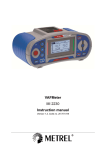
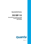
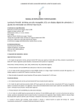
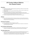
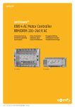
1
PM MOTORCONTROLLER
H60 RFH2406/RES6 with software : NLO02ESC
The RFH2406 serie is a 4 quadrand speed controller specially suited for permanent magnet DC motors
(PMM).
The speed controller is a microprocessor controlled equipment with self check and alarm diagnostic
already integrated.
This equipment has been developed in order to achieve very compact and high performance on small
medium sized electric vehicles. The RF050H has standard regenerative braking.
The line contactor is already integrated on board and this simplifies the mounting and wiring operation
on the vehicle. In case of any failure sensed by the control section of the microprocessor the line
contactor is opened thus preserving safety during operation.
The MOSFET power technology assures best performance at high frequency chopping.
Application of high frequency reduces battery over current peaks during start of electric vehicle thus
prolonging battery service life and reliability.
This power technology assures compact dimensions to the power pack of the equipment.
No di
re
with r ction contac
egener
tors
a
t
i
v
integra
e
ted lin braking
e conta
ctor
L = 161mm
B = 105mm
1
2
3
4
5
6
7
8
9
10
Warning:
mm
Technical
features:
146
7
Mosfet power technology.
Supply: 24V or 36.
Users frequency 15 kHz.
Self-check and alarm diagnostic led.
Microprocessor controlled.
Safety circuits and line contactor already
Integrated.
Wiring connection trough a 12 pole Minifit
connector.
151mm
1
2
3
4
5
6
H = 49mm
Main features:
Dimensions
Electric potentiometer: 5 kOhm with 320°
electric angle.
Adjustments: acceleration,
braking(regenerative), Max.speed forward,
max. speed reverse,reverse
Time, temperature motor.
Supply: 24 or 36V DC.
Efficiency with a 50% power output: >90%.
Max. current: 40/50 or 60 A.
External enclosure for protection (Ip53)
Alarms: line contactor fault, motor circuit
open, insufficient line filter capacitor charge,
over temperature, motor already rotating at
start up and software fault.
Max. working temperature (on mosfet power
block) : 85°C +/- 5%. If failure is present the
equipment doesn't start, except in case of
sensed over temperature. In this case the
Equipment still works at reduced power.
Chopping frequency: 15 kHz.
Line contactor on battery positive side
Already integrated.
Service Manual
Don’t change the polarity of the controller, this will
damage your controller.
w w w.alpatek.com
Calibrator TDA/1:
The calibrator TDA/1 is developed for easy programming the RF050H. The
housing is of durable material to work with it daily.
Functions TDA/1:
-
To program the controller for every function from 0 to 100%
-
OK led green, burns when key-switch is on and the calibrator is
connected correctly.
-
Diagnostic led red, also present on the controller. This led shows
trough a number of flashes what is wrong. By means of the alarm
report the fault can be located.
-
Battery polarity diagnostic led yellow. When the battery is wrong
connected the led burns directly. Immediate disconnect the battery
connector.
TDA-1
How to use TDA/1:
Program procedure:
Warning:
The calibrator has 6 adjust functions for an optimum adjustment of the
controller.
1
2
3
4
6
8
Acceleration
Deceleration
Maximum Speed forward
Maximum Speed reverse
Brake delay time
Rapid reversal speed
0,5 - 4 sec.
0,5 - 4 sec.
0 - 100%
0 - 100%
0,5 - 5 sec.
-
Select an adjustment trough turning the function knob.Select the
adjustment trough turning the VAL (value) knob between 0100%.
-
To save this adjustment in the processor, press the DATA ENTER
knob for 1 sec. minimum. Ones the adjustment is accepted the red
led will flash for a short moment. Now the adjustment is saved in the
processor to start with a new adjustment.
-
The adjustments can be saved in the processor directly during
working. In this case the new adjustment is immediate active.
-
The calibrator is active when connected and the key-switch is turned
On.
-
To remove the calibrator: first turn off the key-switch to avoid any
damage on the controller or calibrator.
-
The I-max measurement is not active during adjusting the controller.
Therefore it is important that you don't drive full gas when the
calibrator is connected, this to avoid damage on the calibrator.
-
During driving or plugging or during auto plugging the calibrator is not
active because the microprocessor has to check the safety circuit.
-
Do not turn off the key-switch while pressing the DATA ENTER knob
or else the microprocessor can save the wrong adjustment.
w w w.alpatek.com
Function red led: every fault that is located by the controller, is shown by a number
of flashes of the red led.
DIAGNOSTIC
LED
DIAGNOSTIC
LED
1
x
Fail of micro switch correct start sequence. This generally happens if
at start (key inserted) one of the direction micro switch is already
closed.
Function red led:
every fault that is located by the controller, is shown by a number
of flashes of the red led.
2
x
Battery under voltage or discharged. This alerts that the voltage isn't
enough
for a switch
correctcorrect
operation
the vehicle.
1
x
Fail of micro
startofsequence.
This generally happens if
at start (key inserted) one of the direction micro switch is already
3
x
Diagnostic code not used
closed.
4
2
xx
5
3
x
x
6
4
xx
5
7
x
x
6
x
8
7
xx
9
8
x
x
9
x
Electric under
motor voltage
circuit isorsensed
to be This
opened.
Battery
discharged.
alerts that the voltage isn't
enough for a correct operation of the vehicle.
Speed controller internal fault or electric motor has a fault to ground
(insufficientcode
insulation
level).
Diagnostic
not used
Potentiometer
fault. This
code istonot
in case of a 2 wire
Electric
motor circuit
is sensed
be active
opened.
connected potentiometer.
Speed controller internal fault or electric motor has a fault to ground
High power insulation
on power MOSFET
unit. This alarm is active every time
(insufficient
level).
there is a temperature of 75°C +/ - 5% on the MOSFET. The alarm is
active till the temperature
returns
below
75°C.
During
the max.
Potentiometer
fault. This code
is not
active
in case
of aalarm
2 wire
current
is
reduced
to
safety
level
for
the
equipment
reliability.
connected potentiometer.
The motor
sensed
be already
in This
rotation
when
equipment
High
powerison
powertoMOSFET
unit.
alarm
is active
every time
started
(keyinsertion).
This
happens,
for
example,
whenThe
thealarm is
there is a temperature of 75°C +/ - 5% on the MOSFET.
equipment
is
started
during
descending
a
slope.
active till the temperature returns below 75°C. During alarm the max.
current is reduced to safety level for the equipment reliability.
Software has a fault.
The motor is sensed to be already in rotation when equipment
started (key- insertion). This happens, for example, when the
equipment is started during descending a slope.
Software has a fault.
B+
B+
M1
M2
B-
M1
M2
B-
Fuse 60A
PM Motor
Fuse 60A
PM Motor
Battery
w w w.alpatek.com
Battery
Software version : NLO02ESC
1
2
3
4
5
6
7
8
Adjustments:
Accelleration
Decelleration
Max speed FW
Max speed RV
Not in use
Brake delay time
Not in use
Rapid reversal speed
24V
FUSE
ustments:
B+
celleration
ecelleration
ax speed FW
ax speed RV
t in use
ake delay time
t in use
pid reversal speed
M1
MOTOR
BELLY BUTTON
M2
B+
BRAKE
12
FUSE
6
B-
M1
B-
M2
5
11
4
10
3
9
2
8
1
7
POTENTIOMETER
NEGATIVE
POSITIVE
FUSE
1
2
3
4
5
6
7
8
FUSE
KEY SWITCH
BRAKE
REVERSE
Adjustments:
REVERSE
BELLY BUTTON
11
12
NEGATIVE
5
9
10
6
3
8
4
2
7
FORWARD
24V
1
POSITIVE
MOTOR
FORWARD
POTENTIOMETER
KEY SWITCH
Accelleration
Decelleration
Max speed FW
Max speed RV
Not in use
Brake delay time
Not in use
Rapid reversal speed
FUSE
Software version : NLO02ESC
B+
** When the Belly Button is not used ; connect Pin nr. 9 directly to Battery negative **
M1
MOTOR
24V
w w w.alpatek.com
M2