1
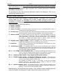
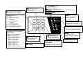
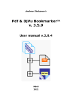
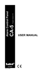
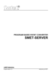
USER MANUAL Alarm Control Panel CA6 plus (Program Version 5.05) ® GDAŃSK ca6pu_e 06/04 WARNING In order to avoid any operational problems with the control panel, it is recommended that you become familiar with this manual before you start using the equipment. Making any construction changes or unauthorized repairs is prohibited. This applies, in particular, to modification of assemblies and components. Maintenance or repair operations should be performed by authorized personnel (i.e. the installer or factory service). Telephone terminals of the panel should be connected to PSTN lines only. Connecting to ISDN lines may lead to damage of the equipment. In case of upgrading the PSTN line to ISDN, system owner should contact the installer. CAUTION! The alarm system is fitted with a battery. After expiry of its service, the battery must not be thrown away, but disposed of as required by the existing regulations (European Directives 91/157/EEC and 83/86/EEC). Latest EC declaration of conformity and product approval certificates can be downloaded from our Web site www.satel.pl ATTENTION ! An efficient security system does not prevent burglary, assault or fire from happening, however it diminishes the risk that such a situation will cause no alarm or notification. Therefore, the SATEL Company recommends that operation of the whole security system be regularly tested. History of the manual updates – end of manual. Control Panel CA-6 plus Control panel CA-6 plus is a modern, microprocessor-based control panel designed for burglary and assault signaling systems. The CA-6 plus panel controls the alarm system, responds to information coming from the system detectors about an intrusion on a protected area, signals and informs about the event. The panel is designed to be operated with LED-equipped remote keypads. Basic functions: • signaling burglary, panic and fire alarms, • informing of alarms with telephone messages or messages to a paging system, • the possibility of answering phone calls and informing the user of system status (whether there has been an alarm condition since its arming), • MONITORING - communication with telephone monitoring stations (real-time transmission of detailed information about specified events in a protected facility), Features: • panel operation controlled with LED-equipped remote keypads, • remote control by means of a telephone (selected functions) – interfacing with MST-1 module, • real-time status display for all 8 zones, • alarm and trouble events logs available (for up to 255 events), • the system can be divided into 2 partitions (subsystems), • system can be operated by up to 13 users with independent access codes - the access codes can have different authority level, their use being recorded in the event memory log, • locks, lighting system and other devices can be remotely controlled with the panel keypads, • alarms PANIC, FIRE and AUX can be activated from the keypad, • a number of system arming procedures (with automatic bypassing, with no exit automatic bypassing), • internal clock capable of automatically arming and disarming the system, • automatic diagnostics of the basic elements of the system. Armed modes To adapt the alarm system to various needs, the control panel CA-6 plus offers several armed modes: Armed mode (full) The mode in which detectors connected to the panel control the protected facility and violation of the protected areas is signaled by the panel with all available means (sirens, reporting to telephone monitoring stations, telephone messages). Silent armed mode Armed mode in which alarms are signaled only in the panel keypads. The installer can decide which of the detectors are automatically by-passed on entering this mode; he can also choose signaling device to be used in that mode. User Manual 2 Partially armed mode Installer can determine the detectors in the system which will be excluded from the supervision on arming the system with the special access code (authority level 7). The user can, by entering an appropriate code, arm the system fully or in a chosen part only. Stay armed mode In this mode the panel enables automatic bypassing of chosen detectors if after arming the system the user neither left the supervised area, or violated the exit/entry zone. Operating instructions Operating of the alarm system consists basically in arming and disarming the system (setting supervision mode) and responding appropriately to the information the control panel may signal on the keypad. The keypad displays information about the status of the alarm system by means of 15 LED controls and acoustic signals. LED functions • POWER (green) - power supply status on - power supply OK, blinking - low battery off - no AC power • PHONE - LED on when telephone line is engaged by the control panel, • TROUBLE - LED blinks when the control panel detects technical problems or telephone messaging system trouble, • AALARM, BALARM – LED on - signals alarm in partition A or B, respectively, • AARMED BARMED - indicates the status of a partitions - blinking - (while the ALARM LED is off) signals the start of the countdown of exit delay; on - signals armed mode. • 1 + 8 - the status of zones is shown: - the LED off - zone is free (not violated), the LED on - zone is violated, the LED is on with extinguishing every two seconds, the LED blinking quickly - zone caused an alarm condition, the LED winking every two seconds - zone tamper circuit caused an alarm, the LED slow blinking - zone by-passed. Conditions signaled acoustically in the keypad The signals produced to confirm the operation on the keypad: • three short - system arming/disarming confirmation, deactivating type 13 (BI switch) output, • two long - wrong access code, canceling a function or incorrect data for a function, • three long - an attempt to arm the system when it is not ready (with violated PRIORITY option zones - see Arming), • four short, one long - correct user function completion, activating type 13 (BI switch) output, or activating type 12 (MONO switch) output. System events signaling: • continuous signal - alarm condition, CA-6 plus SATEL 3 • intermittent signal - fire alarm, • one short signal every 3 seconds - entry time countdown, • one long signal every 3 seconds - exit time countdown, • two short signals every 3 seconds - trouble, • five short - CHIME zone violated, • five long - DAY/NIGHT zone violated. The installer determines which events and in which keypads are to be signaled acoustically. User Access Codes For everyday operation of the system users are assigned access codes. The control panel comes with one default code (master user code): 1234 for partition A and B. It is possible to program additional 12 user access codes with assignment to partition A, B or both partitions. Master user, while programming new access codes, assigns specific authority levels to them i.e. determines which of the panel functions are accessible to a particular user, and which are not. Arming [Access code][#] Arming is only possible when the partition is signaling no alarm and is not already armed: ALARM and ARMED LEDs are off. In order to arm the system, access code should be entered and confirmed by pressing the [# ] key. If, while entering the code, user makes a mistake, the [*] key should be pressed and the code re-entered. The access codes should be entered very carefully. Giving a wrong access code three times in succession may activate an alarm recorded in the event log as „3 wrong codes alarm”. If the code is entered correctly and arming is possible, the panel will confirm the entry with three short beeps. At the same time ARMED LED starts blinking to indicate that the exit delay countdown has started. The installer determines the value of the exit delay time and the way the acoustic signaling works. The panel may fail to arm the system if: • the panel is not ready for arming: there are specifically designated zones which cannot be violated while the system is being armed and one of them is being violated at the time of arming - the panel signals the situation with three long beeps. In such a case, you should wait until all the zones are ready (the LEDs 1+8 go off) and arm the system again. If one of the zones remains violated (one of the LEDs 1+8 is on, which may be caused, for example, by a detector trouble) the armed mode can be switched on after bypassing the zone (with function 4), • the entered code is invalid - which is signaled by the panel with two long beeps. • battery trouble - three long beeps (proper option is selected to prevent the system from being armed in case of battery trouble). Quick Arming [0][#] The user can quickly arm the system with no access code, by pressing in turn: [1][#] - arming partition A - User Manual 4 [2][#] - arming partition B [3][#] - arming both partitions The quick arming takes place irrespective of whether any detectors are violated, or not. The Quick Arming function can be disabled by the installer. He can also install a special key for quick arming of the system. Disarming and alarm clearing [CODE][#] When the panel is armed (ARMED LED is on or blinking) or signals an alarm (ALARM LED is blinking), entering the access code confirmed by pressing the [#] key can disarm the system or clear the alarm. If, while entering the access code, the user makes a mistake, the [*] key should be pressed and the code re-entered. The panel confirms the entry with three short beeps and extinguishes the ALARM/ARMED LEDs. The control panel will not be disarmed and the alarm will not be cleared if: • the access code is incorrect, • the access code authority level does not allow disarming (for example, authority level 3 or 9 - see "User Functions" - "New User") • the access code is not assigned to armed or alarming partition, It is possible to cancel the alarm without disarming the system with the authority level 0 access code. If the system is divided into two partitions, it is possible to arm or disarm one partition (with that partition code) while the other is alarming or armed. Using the code assigned to both partitions will always result in disarming or clearing the alarm if one of the partitions is armed or alarming. Clock Controlled Arming and Disarming Arming and disarming of the system can be controlled with a control panel clock. The installer can program the exact hour and minute of arming/disarming of the system. Arming and disarming will occur every day at a specified time. The control panel can also be armed with a clock and disarmed manually by a user. System Status Telephone Messaging The owner of the facility where the CA-6 plus control panel installed can check by the phone if there has been an alarm condition. In order to do so he has to phone the protected site - the control panel will answer the phone and will brief the caller on the system status. The control panel will answer telephone calls only when the system in the whole protected facility is armed. Having received the call the control panel sends: • one beep a second - if, since the last arming, there has been no alarm condition; • speech synthesizer message - if the alarm occurred within the last hour; • sequence of five short beeps - if the alarm occurred, but more than an hour ago. The panel can answer calls in one of two modes: • single calling mode - the panel answers the call after a specified number of rings (as is the case with a standard answering machine); after receiving the call the panel doesn’t answer any more calls for 5 minutes. CA-6 plus SATEL 5 • double calling mode - to establish connection with the panel you should call it and after hearing the specified number of, so-called, return signals (steady tone for a second and break for 4 seconds - the signal is similar to the telephone ringing tone) hang up the receiver and call once more (within 5 minutes) - the panel will answer the call immediately. The installer decides if the function is on and how the control panel answers the phone calls (number of rings, double calling etc.) Control Panel Interfacing with MST-1 Telephone Control Module The CA-6 plus control panel with program versions 3.04, 4.00 and later can work together with the MST-1 remote control module manufactured by SATEL. The module makes it possible to operate the alarm control panel by means of a telephone fitted with Dual-Tone Multi-Frequency touch-tone dialing unit. The control can be effected from a telephone the control panel calls up during voice messaging (immediately after the message from speech synthesizer is reproduced), or after getting through from any telephone set. Having received the call, the module working together with the CA-6 plus control panel reports its readiness with two beeps (high-pitched and low-pitched). Two types of operations are possible: 1. Checking the state of control panel partitions and/or zones. 2. Performing the user functions. CALLING PROCEDURE [0][#] [1][#] [2][#] [9][#] [ACCESS CODE][#] [ACCESS CODE][¼][4] [ACCESS CODE][¼][5] [ACCESS CODE][¼][7] [ACCESS CODE][¼][8] DESCRIPTION OF FUNCTION End of telephone connection with control panel Checking the state of Partition 1 Checking the state of Partition 2 Checking the state of zones Arming/disarming, alarm clearing Zone bypassing Silent arming Control of MONO switch type output Control of BI switch type output The table shows functions performed by the MST-1 module. The control is effected by using the DTMF signals from the telephone keypad. In order to call a particular function, press in turn the telephone keys according to the calling procedure shown in the table. Signaling the partition state: • three short beeps – the partition is disarmed; • four short beeps and a long one – the partition is armed. The partition alarm or the alarm memory are signaled by a series of short beeps (alternately, high-pitched and low-pitched) lasting approx. 2.5 seconds immediately following the signals relevant to the partition state. Using the „Check zones state” function you can read out information, which of the LEDs (on the LED type keypad) are constantly on or blinking. Indication of an armed partition zone means the memory of alarm triggered by that zone, while indication of a disarmed partition zone means violation of the given zone. In the CA-6 plus control panel, the LED numbers are closely tied to those of the zones. - User Manual 6 Procedure of checking the state of zones: • After the function [9][#] is called first time, the module generates short beeps, the number of which is equal to the least number of LED in the LED keypad. If none of the LEDs is on, the module generates two long beeps. • Next calling of the function [9][#] will indicate the next LED. Continue the review until you hear two long signals, which is an indication that the next LEDs are not lighted. Recalling the function (after two long beeps) will start again the review of the state of zones (i.e. the numbers of lighted LEDs). The user functions, protected with an access code, are performed in the same way as when using the control panel keypad (see a description below in the User Manual). The acoustic signaling heard in the telephone handset is identical to the keypad signaling. The other user functions (not specified in the table), the HOLD DOWN type functions, quick arming of partitions, and entering the service mode through the MST-1 module are disabled. The function [0][#] ends the telephone connection – the control panel „hangs up”. Similarly, the control panel itself will end the telephone connection, unless it receives within 30 seconds a DTMF signal from a telephone. „HOLD DOWN” User Functions The functions are available for every user (without using the access code). They are activated on longer depressing the function key. ALARM MEMORY VIEWING g Holding down the key 5 displays the information about the most recent alarm condition. Pressing any key (except for the [*] key, which quits memory log viewing immediately), displays the previous alarm conditions recorded, until the most recent information appears. The panel signals three types of alarms: • zone alarms: one of the LEDs 1 to 8 is steadily on (burglary alarms, panic alarms, fire alarms etc. depending on how the functions of the zones were set up by the installer) • zone tamper alarms: one of the LEDs 1 to 8 is blinking (this type of alarm signals an attempt of dismantling the panel, detectors or wiring trouble), • keypad activated alarms: the LEDs 1 to 8 are steadily on and one of the LEDs 1 to 5 is blinking. The LEDs have the following meaning: 1 - fire alarm from keypad 2 - auxiliary alarm from keypad 3 - panic alarm from keypad 4 - keypad tamper alarm 5 - three wrong access codes alarm Trouble Memory Viewing h The function allows the panel user to view the information about system trouble conditions recorded by the panel. CA-6 plus SATEL 7 On activating the function the POWER and PHONE LEDs go on and the TROUBLE LED starts blinking. At the same time one of the LEDs 1÷8 or one of the AB-AB LEDs goes on indicating the type of trouble (see: function description CURRENT TROUBLE CHECK-OUT) On pressing any key the previously detected troubles are displayed. The [*] key cancels the viewing function. i Current Trouble Check-Out When the control panel signals a trouble detection (TROUBLE LED is blinking), holding down the key 7 activates the Current Trouble Check-out function. On activating the function the TROUBLE LED and the LEDs indicating current trouble conditions go on. Pressing any key quits the function. The LEDs have the following meaning: 1 - output 1 trouble, 2 - output 2 trouble, 3 - output 3 trouble - no load (for example, siren wires are cut) or overloading (short circuit) - it usually requires a specialized service. 4 - 230 VAC loss - the panel is equipped with a limited time battery backup; if the AC loss trouble is signaled despite an efficient electrical installation, service should be called. 5 - battery trouble - the battery voltage is too low (lower than 12V under operational load). The state may hold for several hours after AC supply loss (or after connecting a discharged battery). The battery charging time depends on its capacitance (the battery is charged with limited current of approx. 350mA, the time necessary for testing the battery status is about 12 minutes). 6 - keypad power supply trouble - signals an installation error; servicing is necessary (the trouble can be displayed only when viewing the alarm memory). 7 - clock loss - it takes place on disconnecting and reconnecting the control panel; the clock should be set with user function 6. 8 - monitoring trouble - it is signaled when the panel cannot communicate with monitoring central station and events from supervised area cannot be reported; when this message remains on for several minutes or more, monitoring is ineffective and service should be called immediately. AARMED - no voltage on the telephone line - the message indicates that the telephone line is cut off. It may also indicate that the receiver of the telephone connected to the same line is off hook for longer than the time specified by the installer. BARMED - telephone line trouble - busy signal on lifting the receiver, AALARM - telephone line trouble - no signal on lifting the receiver - both point to the reason why telephone messaging system failed (no signal on line on lifting the receiver or busy signal instead of steady tone) The signaling of troubles 10 and 11 will remain on until next successful telephone connection. The condition can be cleared by calling the Trouble Check-out function and depressing the [#] key. BALARM - system memory error - the message appears on erratic microchip operation of the system (it may be caused by strong electromagnetic interference produced by lightning) - in most cases service should be called. Depressing any key terminates the function. If the acoustic trouble signaling was set up by the installer, activating the Trouble Check-Out function will turn it off. - User Manual 8 SWITCHING THE CHIME ON/OFF j The function gives the user the possibility of switching the chime on/off (acoustic signaling of the violation of specified detectors) by means of the keypad. Three short beeps in the keypad confirm switching off of the chime signaling. Four short and one long beeps confirm switching the chime on. The installer decides which zones can use chime to signal their status. FIRE ALARM (*) The function makes it possible to trigger the fire alarm from the keypad. AUXILIARY ALARM b The purpose of the alarm depends on the current needs. It may, for instance, be an emergency call for help. The function may transmit an appropriate message about the auxiliary alarm to the monitoring station and activate the voice messaging. PANIC ALARM (#) The function makes it possible to trigger the panic alarm from the keypad. The keypad activated alarms can be disabled by the installer. User functions If the control panel is not armed and is not signaling any alarm, users with an appropriate authority level can access several functions useful in everyday operation of the alarm system. Additionally, two of the mentioned functions (7 and 8) are also accessible when the control panel is armed or alarming. The user functions are activated by entering the user access code and confirming it with the [*] key (and not the [#] key as was the case with arming/disarming the system and clearing the alarm). The panel confirms the operation with the POWER, PHONE and TROUBLE LEDs blinking simultaneously. Then, press the key with the selected function number: User functions: • access code change [CODE][*][1] • new user (new code) [CODE][*][2] • delete user (code) [CODE][*][3] • bypassing panel zones (partition) [CODE][*][4] • switch on silent armed mode [CODE][*][5] • system clock programming [CODE][*][6] • MONO switch on [CODE][*][7] • BI switch status on/off [CODE][*][8] • power supply reset [CODE][*][9] • DOWNLOADING function start [CODE][*][0] NOTES: • The functions [CODE][*][7] and [CODE][*][8] are always accessible, irrespective of whether the panel is armed or not. • The functions [CODE][*][2] and [CODE][*][3] are only accessible to the master user. CA-6 plus SATEL Access Code Change 9 [CODE][*][1] The function allows changing the access code of the user who activated it. On calling the function, enter a new code and confirm it by pressing the [#] key. The function is accessible to the master user and users with authority level 1, 2 or 7. EXAMPLE: changing the access code from [1234] to [7890] [1234] [*] - calling the „user function” mode confirmed with one short beep and POWER, PHONE and TROUBLE LEDs blinking. [1] - calling the „change access code” function, confirmed with two short beeps. [7890] [#] - entering the new code digits and confirmation with four short and one long beeps. New User [CODE][*][2] The function is only available to the master user. The user can add new users to the system, assign access codes to them, determine their authority level and specify assignment to partitions. As new users are added, the panel will assign new, consecutive numbers to them. The number of the user being programmed is indicated by one of the LEDs blinking: 1÷8 - users 1÷8, AARMED - user 9, BARMED - user 10, AALARM - user 11, BALARM - user 12. The LEDs indicate current users, the ones that are off - empty items. Up to 12 users can be entered (plus the master user). After calling the function the panel waits for new user access code entry (4 to 6 digits after which the [#] key should be pressed), then for a digit (0 to 9) determining the new user authority level and one more (1, 2 or 3) determining partition assignment. The access code can have the following type/authority levels: 1 - all functions available except for adding and deleting users, 2 - arming and disarming functions, plus changing access code available, 3 - arming and disarming function available - disarming, however, on condition that the same access code armed the system, 4 - access code-trap: arming and disarming functions are available but after disarming the system the "DURESS" message is sent to the monitoring station 5 - activates MONO type output (the use of the output is determined by the installer) 6 - switches BI type output (the use of the output is determined by the installer) 7 - partial arming: the code arms the system with simultaneous bypassing of a group of zones (determined by the installer in service functions), except for that the code gives the same authority as any level 2 code, 8 - arming and disarming available without the possibility of changing access code, 9 - arming only available, 0 - clearing the alarm only available Partition assignment: 1 - partition A code 2 - partition B code 3 - both partitions code - User Manual 10 EXAMPLE: entering the user code [3546] with authority level 1, controlling only the B partition; master user code [1234] [1234] [*] - activating the „user function” mode by master user, confirmed with one short beep and blinking of the: POWER, PHONE, TROUBLE LED’s [2] - calling the "New user" function, confirmed with two short beeps signal [3546] [#] - entering new codes characters, confirmed with three short beeps [1][2] - determining the authority level and specifying assignment to partition that is controlled with the code; automatic cease of the function, confirmed with four short and one long beeps NOTES: • If the function is terminated with the [#] key without any authority level and partition assignment number, the panel will assign the code (authority level 1) for the first partition. • The access code types 5 and 6 can be used in the following way: 1. In the basic mode of user functions ([CODE][*]7 or [CODE][*]8), which allows multiple control of single outputs (see the description of user functions). 2. In the mode used in previous versions of the control panel (i.e. [CODE][#]), which simultaneously controlled all the outputs of a given type belonging to the partition the particular code was assigned to. • Using the authority 5 level code or calling the function 7 is recorded in the event memory as „Entry/Exit (guard rounds)”. • To make the control possible, there must be conformity between the access code type, output type, and the partition assignment. Delete code [CODE][*][3] The function’s purpose is to delete the codes of current users to revoke their rights to use the system. The function is accessible to the master user only. EXAMPLE: deleting the third user’s access code (master code = 1234) [1234] [*] - activating the „user function” mode by master user, [3] - calling the „delete code” function, the zone LEDs indicate the partition users numbers. [3] - selecting the code to delete; the LED of the chosen code starts blinking [#] - selected user code deletion; four short and one long beeps signal the end of the function. After entering the deleted user access code the panel waits for confirmation that the selected user is to be deleted. If not, the [*] key should be pressed, if yes, the [#] key. Zone Bypassing [CODE][*][4] The function makes it possible to bypass zones in order to arm the alarm system only partially or disable temporarily malfunctioning detectors. Only disarmed zones can be bypassed. After the bypass is set, the zone LEDs start blinking. The zones remain bypassed till the next disarming of the system or manual disabling of the bypass function. EXAMPLE: bypassing lines 3 and 5 (master access code = 1234) [1234] [*] - activating the „user function” mode by master user, [4] - calling the „partition line bypass” function, [3] [5] - selecting line number 3 and 5; after each of the numbers entry, the panel will confirm it with two short beeps, [#] - confirming the data and, at the same time, exiting the function. While the function is active, on entering the line number, the panel signals bypassing the line with two beeps, and unbypassing with one. Two long beeps mean that the line belongs to another partition, or is armed and its bypassing is not possible. The function is available only to the master user and user with authority level 1. CA-6 plus SATEL Silent Armed Mode 11 [CODE][*][5] In silent armed mode the alarms are signaled only in keypads and by sending an appropriate message to monitoring station. The installer decides if silent armed mode is active in the entire protected facility or if, in a selected area, it will be disarmed. The function is not available to users with authority level 5, 6, 0. Setting Time [CODE][*][6] The function enables setting the panel’s clock. The programming procedure is as follows: - HOURS, MINUTES, confirmation ([H][H][M][M][#]), - DAY, MONTH, confirmation ([D][D][M][M] [#]), - YEAR (if it is 1998, 1999 two last digits are enough), confirm It is possible to quit the function earlier after programming either time or date by pressing the [#] key twice. The function is available only for the master user and a user with authority level 1. Activating the MONO SWITCH type output [CODE][*][7] The purpose of the function will be determined by the installer. It can activate e.g. electric locks, bells, signal lamps, or any other devices. After calling the function, the control panel generates two short beeps and waits for the (1-5) output number key to be pressed. Provision is made for multiple control of the same output or control of different outputs of the MONO switch type after single calling of the function. Correct performance of the control is confirmed by four short and one long beeps, and refusal of the control - with two long beeps. The control panel may refuse control, if the output is not of the "MONO switch" type or if it belongs to another partition. Pressing the key [#] or [*] will end the function. The control panel will automatically end the function if none of the outputs is of the „MONO switch” type, or if no key on the keypad is depressed for 40 seconds. The function is accessible to the master user, as well as to the users with authority levels 1 and 5. EXAMPLE: successive control of the outputs 4, 5, 4 (master code=1234) [1234] [*] calling the "user function" mode by the MASTER user [7] [4] [5] [4] [#] - calling the function of "activating the MONO switch type output " (two short beeps) monostable triggering of the output 4 confirmed by four short and one long beeps monostable triggering of the output 5 confirmed by four short and one long beeps monostable retriggering of the output 4 (four short and one long beeps) end of the function (four short and one long beeps) Changing over the BI SWITCH type output [CODE][*][8] The purpose of the function will be determined by the installer. It can be used e.g. for switching on external lighting or any electrical equipment. After calling the function, the control panel generates two short beeps and waits for the output number key to be pressed. Provision is made for multiple control of the same output or control of different outputs of the BI switch type after single calling of the function. Activation of the output is confirmed by four short and one long beeps, - User Manual 12 and its deactivation - with three short beeps. Refusal of control is signaled with two long beeps. The control panel may refuse control, if the output is not of the "BI switch" type or if it belongs to another partition. Pressing the keys [#] or [*] will end the function. The control panel will automatically terminate the function if none of the outputs is of the „ BI switch” type, or if no key on the keypad is depressed for 40 seconds. The function is accessible to the master user, as well as to the users with authority levels 1 and 6. Power Supply Reset [CODE][*][9] The function is used for handling special detectors equipped with individual violation memory which is cleared by switching off power supply (for example smoke detectors, broken glass detectors) The function temporarily disconnects power supply for such detectors. The function is available to the master user and a user with authority level 1. Start Download [CODE][*][0] The function can be activated by the master user and a user with authority level 1. It starts remote telephone connection between the control panel - service PC. The function establishes communication with the computer when the option of establishing connection from outside (from the computer) is disabled. On activating the function the panel engages the telephone line and connects to the service computer. If the panel is unable to connect first time, it will attempt to establish connection three more times. During the downloading process the telephone line will be busy. Service can temporarily free the telephone line suspending the downloading and recall the panel to continue data exchange. The installer should inform the users about that so that they do not answer the incoming calls to allow re-establishing connection and correct completing of the transmission. Technical Reliability of the Alarm System The alarm system consists of devices whose reliability is vital for effectiveness of offered protection of the site. Components of the alarm system are subject to various outside influences, for example, weather conditions (outside signaling devices), lightning (overhead telephone lines, power lines, outside signaling devices), mechanical damage (keypads, detectors). Only regular testing of the alarm system operation makes it possible to keep a high level of burglary and fire protection. The control panel is equipped with a number of safeguards and auto diagnostic functions for testing reliability of the system. The control panel signals detection of a trouble by switching on the TROUBLE LED on the keypad. The signal should be immediately taken care of - if necessary, the installer should be consulted. It is necessary to periodically test the alarm system reliability. Make sure that the control panel reacts to violation of particular detectors, that their fields of vision are not covered or obstructed, that there is a reaction to opening the protected windows and doors, and that the signaling devices and telephone messaging are in a workable condition. The installer determines in detail how the system should be controlled. It is recommended that the installer carry out periodic maintenance of the alarm system on request of the user. CA-6 plus SATEL 13 It is in the user’s best interest to predict unexpected alarm conditions and plan appropriate procedures. It is vital to be able to verify the nature of the alarm and determine its source based on the keypad information, as well as to take an adequate action, for example, to organize evacuation. History of changes in the manual contents. Given below is a description of changes in the manual contents as compared with the software version v3.03. Firmware Description of changes version The way the user functions 7 and 8 are performed has been changed (see 3.05 p. 11), thus changing the way the access code types 5 and 6 are used (p.11). A new section has been added regarding telephone operation of the control 4.01 panel working together with MST-1 telephone control module (see page 5). The way of panel reaction to entering the [CODE][*] from keypad has been changed. Now the panel always enters the user functions mode and enables the function 7 or 8, irrespective of whether it is armed or not. The other user functions are only accessible when there is no alarm and the system is disarmed (page 10). 5.02 Disarming is only performed by entering the [CODE][#] from keypad (page 4) – previously also [CODE][*]. Audible distinguishing between output activation and deactivation has been introduced in functions 7 and 8 (pages 2, 11). Amendments have been introduced into the notes on page 10. "Battery trouble" added as one of conditions of preventing the system from 5.03 being armed (p. 3). An example for programming new user code (user function 2) has been added (p. 10). 5.05 Words „lighted diode” and „diode” have been replaced with „LED”. SATEL sp. z o.o. ul. Schuberta 79 80-172 Gdańsk POLAND Tel. +48 58 320 94 00 [email protected] www.satel.pl - Controls 1÷8 (zones state) on - zone is violated off - zone is not violated blinking fast - zone alarm memory on with short extinguishing every 2 sec. - zone tamper violated flashes every 2 sec. - zone tamper memory blinks slowly - zone is bypassed g - pressing for 3 sec. i - pressing for 3 sec. activates activates alarm events stored in memory review current trouble condition displaing TROUBLE DISPLAY: Control ON = 1,2,3 - Output 1,2,3 trouble 4 - AC fail 5 - Low battery 6 - Keypad supply fail 7 - Time lost 8 - Reporting trouble AARMED- Tel. line disconnect BARMED- Tel. trouble (wrong signal) AALARM - Tel. trouble (no signal) BALARM - System memory fault 1 1 2 3 4 5 6 7 8 9 * 0 # 2 3 4 5 6 7 8 POWER TELEPHONE TROUBLE A ARMED B A ALARM B POWER on – AC anb battery OK flashes – low battery off – AC fail TELEPHONE on - telephone communication in progress (internal telephones disconnect) TROUBLE on – indicates existence of trouble conditions – press key i for 3 sec. to view trouble display [*] - pressing for 3 sec. activates FIRE ALARM CODE+[*] - User Functions: CODE*1 - change code CODE*2 - new code/user CODE*3 - delete code/user CODE*4 - zone bypass CODE*5 - arming silent CODE*6 - time program CODE*7 - switch MONO CODE*8 - switch BI CODE*9 - supply reset CODE*0 - downloading start j - pressing for 3 sec. activates/deactivates CHIME signaling b - pressing for 3 sec. activates AUX. ALARM h - pressing for 3 sec. activates trouble events stored in memory review. [#]-pressing for 3 sec. activates PANIC ALARM CODE+[#] – arm/disarm partition ARMED on – partition armed, flashes – exit time in progress off – partitiom disarmed ALARM – flashes when an alarm in partition occurs