1
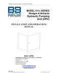
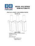
QTEK Design 441 Industrial Road London, Ontario Canada N5V 1T6 [email protected] 877-453-1880 Fax: 519-451-3124 www.qtekdesign.com Operations & Service Manual DStacker GS2 DStacker GS2 Part #: Serial #: Production Code: Manufacture Date: 1 of 9 441 Industrial Road, London, Ontario L5V 1T6 Canada [email protected] www.qtekdesign.com SITE REQUIREMENTS FACILITY SUPPLIED: 1) Electrical Requirements: 120VDC or Solar Option Pneumatic Requirements: None 2) The installation site must have a level concrete surface otherwise the machine’s functionality could be compromised. 3) The site will require a minimum headroom clearance of 16 feet from the floor. 4) The machine will require a minimum clearance around the unit as follows; Left side, right side and rear of unit – 24” minimum Front access clearance – 96” minimum 5) A forklift (minimum 5000 lbs lifting capacity) with a vertical reach of 12 feet”. TOOLS REQUIRED: Hammer drill with a 3/4” & 5/8” drill bit capable of drilling a minimum depth of 6” Heavy hammer Set of wrenches (1/2", 9/16” and 3/4") Utility knife Step Ladder – 6 ft. M000001-‐ar1 QTEK DStacker GS2 – Operations & Service Manual May 2015 Page 2 of 2 441 Industrial Road, London, Ontario L5V 1T6 Canada [email protected] www.qtekdesign.com MACHINE ASSEMBLY ASSEMBLY SEQUENCE: 1) The DStacker GS will arrive on one skid containing two main sections -‐ the machine base and the middle pallet magazine section bolted together with the upper magazine section being nested inside the base. The pallet will also contain the additional installation components which include: a) GS2 Front Latch Assembly b) All machine hardware plus ten (10) floor anchors c) Two (2) Front mesh guards d) Two (2) safety bollards e) Spare Parts – 4 springs, Battery f) Operations and Service Manual 2) Move the complete GS2 Dstacker shipping assembly to installation area accessing the heavier black base end of the shipping skid with a forklift. 3) Remove the lag bolts used to secure machine and components to wooden shipping skid. Remove bollard and guarding off the shipping skid. 4) Remove upper pallet magazine from shipping skid: using the forklift, insert forks under the wooden shipping brace at the top of the upper pallet magazine; place upper pallet magazine on floor; remove wooden shipping brace. 5) Install upper pallet magazine onto middle pallet magazine: using forklift put 5 pallets into upper pallet magazine then lift upper pallet magazine and align onto middle pallet magazine. Install all connecting fasteners. 6) Position Dstacker: using the forklift lift complete assembly with 5 pallets 3” off the shipping skid. Slide the shipping skid out of place, move the GS2 Dstacker onto the floor, placing it in the final installation location. Level the 2 sides to each other by shimming the front of one side. 7) Install the GS2 Front Latch Assembly. Remove the front corner covers and install the GS2 Front Latch Assembly with the four (4) 3/8-‐16 cap screws and lock nuts. Reinstall the front corner covers 8) Secure the machine to the floor by bolting the four corners of the base using the 3/4” anchor bolts supplied by QTEK. 9) Remove counter weight shipping support. Remove equipment access plate and access the shipping support. Cut tie wraps and remove all shipping material. Reinstall equipment access plate after inspecting area for any shipping debris. 10) Install the two (2) mesh guards and braces with 3/8-‐16 cap screws 11) Secure the two (2) Bollards to the floor by bolting the base using the 5/8” anchor bolts supplied by QTEK. 12) Install the photo eye reflector to the mesh guards. 13) Plug in 12 VDC battery 14) Remove all shipping material and clean work site. M000001 QTEK DStacker GS2 -‐ INSTALLATION OPERATIONS MANUAL May 2015 Page 3 of 3 441 Industrial Road, London, Ontario L5V 1T6 Canada [email protected] www.qtekdesign.com OPERATING INSTRUCTIONS: A) PRIMING THE PALLET MAGAZINE: Priming the pallet magazine will occur when initially loading the DStacker or when a previous pallet issue has necessitated the removal of the entire pallet stack. 1) Using a forklift, place one (1) pallet on top of the forks and go into the DStacker from the bottom. From the underside raise the pallet until the front and rear latches flip up past the top board. The latches drop inside the pallet’s opening between the top and bottom boards. Do not raise the pallet beyond this point. WARNING: Contacting the front two latches with the forklift during this step can result in damage and render the machine inoperable. 2) Using a forklift, pick up one (1) pallet with the forks and place on top of the installed pallet 3) Next, load a straightened stack of ten (10) pallets into the magazine making sure to raise the pallet stack above the black base pallet guides when entering the unit. WARNING: To prevent damage to the DStacker and to eliminate dispensing problems, forklift operators must ensure the pallet stacks are vertically aligned and straightened prior to being loaded into the machine. 4) The yellow Pallet Containment Mechanism (PCM), located on each side along the leading edge of the upper pallet magazine, will pivot back out of the way once contacted by the entering pallet stack. The PCM is designed to prevent the pallet stack from falling forward once it is loaded into the pallet magazine. Ensure the 10-‐pallet stack is touching the back wall before lowering them onto the pallets currently resting on the latches. 5) Move the forklift back clear of the Dstacker and not allowing access to the pallets. Hold down the priming switch for 3 seconds, the pallet stack will start to slowly descend to the floor. Once the stack is on the floor, the latches will release the bottom pallet, rise up and be reinserted into the front and rear openings of the second pallet. The Dstacker is now in a safe operable state. 6) Operator should finish filling the rest of the pallet magazine until it reaches the “Pallet Height Limit” indicator at the top of the machine. Do not overfill machine. The pallet magazine must not exceed the maximum number of pallets as indicated. The DStacker is now ready to operate. WARNING: Operators must be certain the pallets do not touch upper support cross braces at the top of the magazine during the loading process. 7) Since the DStacker requires a minimum number of six (6) pallets to operate, the pallet magazine should be reloaded before reaching this minimum number in the machine. B) DISPENSING PALLETS WITH WALKIE RIDER: 1) Check to see the lifting frame is in dispensing position (latches are in the second pallet.) 2) Drive walkie rider into bottom pallet until the backrest is 1/2” from the pallet stack. 3) Raise walkie rider to its full height, which will lift the entire pallet stack. 4) Lower walkie rider forks until the bottom pallet is approximately 1” off the floor. 5) Back out of the DStacker to dispense the pallet. Once the pallet has passed the photo eye the pallet magazine will descend and set the pallet stack on the ground. It will reset the position of the latches into the openings of the next pallet. It is now ready to repeat the process. 6) Replenish the pallet magazine anytime. Do not allow remaining pallet stack to go below the top of the black base. M000001 QTEK DStacker GS2 -‐ INSTALLATION OPERATIONS MANUAL May 2015 Page 4 of 4 441 Industrial Road, London, Ontario L5V 1T6 Canada [email protected] www.qtekdesign.com C) UNLOADING PALLET MAGAZINE: 1) To remove pallet stack, the yellow vertical Pallet Containment Mechanism (PCM) located on each side of the upper pallet magazine opening must first be retracted into the side wall pockets and locked out of the way. 2) Manually push the yellow PCM on one side into its retracted position inside the sidewall. While holding the PCM in this retracted position with one hand, pull the black PCM LOCK OUT lanyard outward with the other hand. Lock the PCM lanyard onto the small black post that will hold the PCM in its retracted position. Be sure to verify that the PCM’s leading edge is inset from the surface of the magazine. This enables the pallet stack to be removed from the magazine without catching on the PCM. Repeat process on other side of the machine. WARNING: This process will disable the pallet magazine safety feature and may result in a less stable pallet stack. Caution should be exercised when attempting to unload the machine. 3) Once the pallet magazine is cleared, operator must enable the PCM again by pressing inward on the PCM while releasing the Lock Out lanyard from the small black post. Test the spring loaded PCM to verify that it is functioning properly again. D) REMOVAL OF A PALLET JAM: 1) In the event that a defective pallet causes the Dstacker to malfunction, the operator will need to remove the pallet stack to retrieve the problem pallet. 2) Using a forklift, remove the entire pallet stack EXCEPT for the bottom two pallets, which should be left in the machine. Be sure to raise the pallet stack straight up above the black base before backing away. 3) If the latches are still caught in the bottom-‐most pallet, lift the second pallet up and out of the machine, ensuring to clear the top of the black base before removing it from the machine magazine. Next lift the bottom pallet straight up slowly making sure the latches flip upward releasing the pallet. Clean area and repeat the loading process above. 4) If at this point it appears that the one remaining pallet was simply jammed, (e.g. the lifting latches were caught on one of the pallets’ cross members) try raising the pallet slightly until the lifting latches fall into the opening between the top and bottom pallet boards. Verify that the latch mechanisms are at the same height. 5) If the problem persists, contact QTEK Design Service at 519-‐453-‐1880. M000001 QTEK DStacker GS2 -‐ INSTALLATION OPERATIONS MANUAL May 2015 Page 5 of 5 441 Industrial Road, London, Ontario L5V 1T6 Canada [email protected] www.qtekdesign.com MAINTENANCE INSTRUCTIONS: DAILY: Clean the floor in the DStacker, removing any pallet debris or dirt. This will ensure the pallets rest evenly on the floor. WEEKLY: Verify that the PCM is functioning properly. Once the pallet stack is below the PCM’s lower extremity, manually push the left PCM into its side recess. The PCM should push back to its starting position. Next, perform test on right side. SEMI ANNUALLY: Test each of the four (4) latch spring mechanisms. Remove the pallet stack (as per Section C) from the DStacker chamber. Manually push one of the four (4) latches inward. The latches should offer some resistance and will return to the outward position once released. Perform the test on the other three latches individually. If the latch does not return, check the integrity of the spring mechanism by removing the side or back interior metal panel. Lubricate the two (2) counterweight chains with a 30-‐wt lubricating oil. Access the chains by removing the exterior back panel. Lubricate the two rear and two front cam follower tracks with 30-‐wt lubricating oil. Check hydraulic oil reservoir level. If oil is below MIN level indicator, replenish to the MAX level indicator mark. PLEASE NOTE: Arctic Supreme 32 Hi-‐Performance hydraulic fluid is to be used in the DStacker GS. M000001 QTEK DStacker GS2 -‐ INSTALLATION OPERATIONS MANUAL May 2015 Page 6 of 6 441 Industrial Road, London, Ontario L5V 1T6 Canada [email protected] www.qtekdesign.com MACHINE ASSEMBLY: photo 1. 1. 4. 4. 6. 7. 8. 9. 11. 2. 3. 5. 7. 5. 7 9 12. 13. M000001 QTEK DStacker GS2 -‐ INSTALLATION OPERATIONS MANUAL May 2015 10 Page 7 of 7 441 Industrial Road, London, Ontario L5V 1T6 Canada [email protected] www.qtekdesign.com OPERATING INSTRUCTIONS: photo 1A. 1A. 2A. 2A. 4A. 5A. 1A. 3A. 6A. 1B. 4B. 2B 3B. 5B. M000001 QTEK DStacker GS2 -‐ INSTALLATION OPERATIONS MANUAL May 2015 5B. Page 8 of 8 441 Industrial Road, London, Ontario L5V 1T6 Canada [email protected] www.qtekdesign.com 1C. 2C. 3C. 1D. 2D. 3D. 3D. 3D. 3D. 3D. 3D. 3D. 3D. M000001 QTEK DStacker GS2 -‐ INSTALLATION OPERATIONS MANUAL May 2015 Page 9 of 9