1
Bent Axis Motors
Parts and Service
Bent Axis
Motors
Table of Contents
Introduction . . . . . . . . . . . . . . . . . . . . . . . . . . . . . . . . . . . . . . . . . . . . . . . . . . . . . . . . . . . . . . . . . . . . . . . . . . . . . . . . . . . . . . . . . . . . . . . . . . . . . . . . . . . . . . . . . . 3
Identification Tag . . . . . . . . . . . . . . . . . . . . . . . . . . . . . . . . . . . . . . . . . . . . . . . . . . . . . . . . . . . . . . . . . . . . . . . . . . . . . . . . . . . . . . . . . . . . . . . . . . . . . . . . . . . . . . 3
Tools Required . . . . . . . . . . . . . . . . . . . . . . . . . . . . . . . . . . . . . . . . . . . . . . . . . . . . . . . . . . . . . . . . . . . . . . . . . . . . . . . . . . . . . . . . . . . . . . . . . . . . . . . . . . . . . . . . . .3
Parts Assembly Drawing and List
Bent Axis Variable . . . . . . . . . . . . . . . . . . . . . . . . . . . . . . . . . . . . . . . . . . . . . . . . . . . . . . . . . . . . . . . . . . . . . . . . . . . . . . . . . . . . . . . . . . . . . . . . . . . . . . . . .4
Bent Axis Fixed . . . . . . . . . . . . . . . . . . . . . . . . . . . . . . . . . . . . . . . . . . . . . . . . . . . . . . . . . . . . . . . . . . . . . . . . . . . . . . . . . . . . . . . . . . . . . . . . . . . . . . . . . . .5
Parts
Pre-loading Spring . . . . . . . . . . . . . . . . . . . . . . . . . . . . . . . . . . . . . . . . . . . . . . . . . . . . . . . . . . . . . . . . . . . . . . . . . . . . . . . . . . . . . . . . . . . . . . . . . . . . . . . . .6
BAV Seal Kits . . . . . . . . . . . . . . . . . . . . . . . . . . . . . . . . . . . . . . . . . . . . . . . . . . . . . . . . . . . . . . . . . . . . . . . . . . . . . . . . . . . . . . . . . . . . . . . . . . . . . . . . . . . .7
BAF Seal Kits . . . . . . . . . . . . . . . . . . . . . . . . . . . . . . . . . . . . . . . . . . . . . . . . . . . . . . . . . . . . . . . . . . . . . . . . . . . . . . . . . . . . . . . . . . . . . . . . . . . . . . . . . . . .7
Shaft & Bushing Kits . . . . . . . . . . . . . . . . . . . . . . . . . . . . . . . . . . . . . . . . . . . . . . . . . . . . . . . . . . . . . . . . . . . . . . . . . . . . . . . . . . . . . . . . . . . . . . . . . . . . . .8
Disassembly . . . . . . . . . . . . . . . . . . . . . . . . . . . . . . . . . . . . . . . . . . . . . . . . . . . . . . . . . . . . . . . . . . . . . . . . . . . . . . . . . . . . . . . . . . . . . . . . . . . . . . . . . . . . . . . .9-13
Check Condition of Parts . . . . . . . . . . . . . . . . . . . . . . . . . . . . . . . . . . . . . . . . . . . . . . . . . . . . . . . . . . . . . . . . . . . . . . . . . . . . . . . . . . . . . . . . . . . . . . . . . . . . .14-15
Assembly . . . . . . . . . . . . . . . . . . . . . . . . . . . . . . . . . . . . . . . . . . . . . . . . . . . . . . . . . . . . . . . . . . . . . . . . . . . . . . . . . . . . . . . . . . . . . . . . . . . . . . . . . . . . . . . . .16-21
Torque Values . . . . . . . . . . . . . . . . . . . . . . . . . . . . . . . . . . . . . . . . . . . . . . . . . . . . . . . . . . . . . . . . . . . . . . . . . . . . . . . . . . . . . . . . . . . . . . . . . . . . . . . . . . . . . . . . .21
Installation Guidelines . . . . . . . . . . . . . . . . . . . . . . . . . . . . . . . . . . . . . . . . . . . . . . . . . . . . . . . . . . . . . . . . . . . . . . . . . . . . . . . . . . . . . . . . . . . . . . . . . . . . . . . .22-23
Controls
Technical Data . . . . . . . . . . . . . . . . . . . . . . . . . . . . . . . . . . . . . . . . . . . . . . . . . . . . . . . . . . . . . . . . . . . . . . . . . . . . . . . . . . . . . . . . . . . . . . . . . . . . . . . . . .24
Testing Procedures . . . . . . . . . . . . . . . . . . . . . . . . . . . . . . . . . . . . . . . . . . . . . . . . . . . . . . . . . . . . . . . . . . . . . . . . . . . . . . . . . . . . . . . . . . . . . . . . . . . . . . .25
Controls EA, EB, EC, ED . . . . . . . . . . . . . . . . . . . . . . . . . . . . . . . . . . . . . . . . . . . . . . . . . . . . . . . . . . . . . . . . . . . . . . . . . . . . . . . . . . . . . . . . . . . . . . . . .26-28
Controls HA . . . . . . . . . . . . . . . . . . . . . . . . . . . . . . . . . . . . . . . . . . . . . . . . . . . . . . . . . . . . . . . . . . . . . . . . . . . . . . . . . . . . . . . . . . . . . . . . . . . . . . . . . . . . .29
Controls HB . . . . . . . . . . . . . . . . . . . . . . . . . . . . . . . . . . . . . . . . . . . . . . . . . . . . . . . . . . . . . . . . . . . . . . . . . . . . . . . . . . . . . . . . . . . . . . . . . . . . . . . . . . . . .30
Controls H1 . . . . . . . . . . . . . . . . . . . . . . . . . . . . . . . . . . . . . . . . . . . . . . . . . . . . . . . . . . . . . . . . . . . . . . . . . . . . . . . . . . . . . . . . . . . . . . . . . . . . . . . . . . . . .31
Controls H2 . . . . . . . . . . . . . . . . . . . . . . . . . . . . . . . . . . . . . . . . . . . . . . . . . . . . . . . . . . . . . . . . . . . . . . . . . . . . . . . . . . . . . . . . . . . . . . . . . . . . . . . . . . . . .32
Controls M1, M2 . . . . . . . . . . . . . . . . . . . . . . . . . . . . . . . . . . . . . . . . . . . . . . . . . . . . . . . . . . . . . . . . . . . . . . . . . . . . . . . . . . . . . . . . . . . . . . . . . . . . . .33-35
Controls PA . . . . . . . . . . . . . . . . . . . . . . . . . . . . . . . . . . . . . . . . . . . . . . . . . . . . . . . . . . . . . . . . . . . . . . . . . . . . . . . . . . . . . . . . . . . . . . . . . . . . . . . . . .36-37
Controls PB . . . . . . . . . . . . . . . . . . . . . . . . . . . . . . . . . . . . . . . . . . . . . . . . . . . . . . . . . . . . . . . . . . . . . . . . . . . . . . . . . . . . . . . . . . . . . . . . . . . . . . . . . .38-39
Controls E5-E6 . . . . . . . . . . . . . . . . . . . . . . . . . . . . . . . . . . . . . . . . . . . . . . . . . . . . . . . . . . . . . . . . . . . . . . . . . . . . . . . . . . . . . . . . . . . . . . . . . . . . . . . .40-41
BAV Critical Dimensions . . . . . . . . . . . . . . . . . . . . . . . . . . . . . . . . . . . . . . . . . . . . . . . . . . . . . . . . . . . . . . . . . . . . . . . . . . . . . . . . . . . . . . . . . . . . . . . . . . . . . . . . .42
Special Tools . . . . . . . . . . . . . . . . . . . . . . . . . . . . . . . . . . . . . . . . . . . . . . . . . . . . . . . . . . . . . . . . . . . . . . . . . . . . . . . . . . . . . . . . . . . . . . . . . . . . . . . . . . . . . . . . .43
2
EATON Bent Axis Motors Parts and Repair E-MOPI-TS003-E February 2005
Introduction
This manual will provide you with service information and
procedures for disassembly and assembly of Eaton® Fixed
and Variable Displacement Bent Axis Motors. Procedures
outlined in this manual will allow you to better service your
motors and obtain the best results possible. To ensure
accuracy of repair and prevent part loss or damage, certain
components or subassemblies are disassembled, inspected,
and reassembled when removed from the motor.
Dry parts with clean compressed air. Avoid cleaning parts
with cloth or paper towel as these can introduce contamination. visually inspect all mating surfaces. Replace any components that have scratches, burrs or evidence of smeared
material. Don’t use abrasive tools including coarse grit
papers, files or grinders on internal parts.
Note: All torque specifications are for lubricated threads.
Bolts for gasketed surfaces should be checked for proper
torque.
Note: All requests or inquiries must be accompanied by the
complete model and serial number.
A good service policy is to replace all old seals with new
seals whenever unit is disassembled. Lubricate seals with
petroleum jelly. Use only clean, recommended oil when
assembling unit. See Hydrostatic Fluid Recommendations in
publication 03-401 and 03-405.
Important: Cleanliness is extremely important when repairing a hydrostatic motor. Before disconnecting the lines, clean
foreign material from exterior of unit. Work in a clean area.
Clean all metal parts in clean solvent.
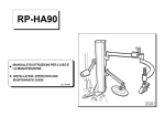
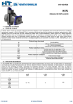
Identification Tag
A - Part Number/Displacement (cu.in./rev.)
Refer to specific motor
assembly part listings for
your Eaton motor when
ordering replacement parts.
Parts lists are available from
Eaton. Sample tag shows
motor identification.
When ordering replacement
parts, you must include the
following information:
BAF Fixed Displacement Motors
11
20, 30
40, 44,
75, 87, 108, 161
225
183BAXXXXXA
383BAXXXXXA
583BAXXXXXA
783BAXXXXXA
983BAXXXXXA
BAV Variable Displacement Motors
524BAXXXXXA
724BAXXXXXA
924BAXXXXXA
{
55, 75, 108
161
225
Displacement
Design Code
Base Part Number
Serial Number Example:
{
{
{
0411 - XXXXXX
04 = Year
11 = Month
XXXXXX = Serial Code Number
Tools Required
•
•
•
•
•
•
•
•
Allen Key
Depth Vernier Caliper
Snap Ring Closing and Expanding Pliers
Screwdrivers
Shaft Puller
Rubber Mallet
Dial Indicator
Torque Wrench
Specifications:
Continuous max. pressure . . . . . . . . . .5100 psi (350 bar)
Peak pressure . . . . . . . . . . . . . . . . . . .6500 psi (450 bar)
Max pressure into casing . . . . . . . . . .35 psi (1,5 bar)
Max. circuit fluid temperature . . . . . . .167°F (+75°C)
Max. leakage fluid temperature . . . . . .195°F (+90°C)
Viscosity range . . . . . . . . . . . . . . . . . . .10-800 cSt (1,85 ¸
105°E)
Normal viscosity range . . . . . . . . . . . .15-60 cSt (2,3¸8°E)
Oil cleanliness . . . . . . . . . . . . . . . . . . .ISO-DIN 4406 = 19/16
EATON Bent Axis Motors Parts and Repair E-MOPI-TS003-E February 2005
3
Parts
Assembly and List
(BAV– Bent Axis Variable Displacement)
TABLE 1.0
BAV PARTS
BENT AXIS VARIABLE DISPLACEMENT MODEL PARTS
2.
3.
4.
5.
6.
7.
8.
9.
10.
11.
12.
13.
14.
15.
16.
17.
18.
19.
20.
21.
4
Gasket
Valve Plate
Housing
Washer
Plug
Cylinder Barrel
Belleville Washers (As Required)
Shims (As Required)
Center Pivot
Bolt
Retaining Plate
Piston Assembly:
Piston + Rod
Straight Keyed Shaft
Splined Shaft
Tapered Roller Bearing
Spacer
Ball Bearing
Spacer
Retaining Ring
Shaft Seal*
22.
23.
24.
25.
26.
32.
Shims
Seal Cover
O-Ring*
Circlip
Bolt
End Cover
EATON Bent Axis Motors Parts and Repair E-MOPI-TS003-E February 2005
Parts
Assembly and List
(BAF– Bent Axis Fixed Displacement)
Axial Threaded Ports
32
TABLE 2.0
Radial Threaded Ports
32
Radial Split Threaded Ports
BAF PARTS
BENT AXIS FIXED DISPLACEMENT MODEL PARTS
1.
2.
3.
4.
5.
6.
7.
8.
9.
10.
11.
12.
13.
14.
15.
16.
17.
18.
19.
20.
21.
Pin
Gasket
Valve Plate
Housing
Washer
Plug
Cylinder Barrel
Belleville Washers (As Required)
Shims (As Required)
Center Pivot
Bolt
Retaining Plate
Piston Assembly:
Piston + Rod
Straight Keyed Shaft
Splined Shaft
Tapered Roller Bearing
Spacer
Ball Bearing
Spacer
Retaining Ring
Shaft Seal*
22.
23.
24.
25.
26.
27.
28.
29.
32.
Shims
Seal Cover
O-Ring*
Circlip
Bolt
Bolt
Bolt
Bolt
End Cover
* Included in seal kit
EATON Bent Axis Motors Parts and Repair E-MOPI-TS003-E February 2005
5
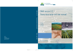
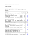
Parts
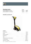
Pre-Load Spring
The system of pre-loading the cylinder barrel has been
modified to improve performance and facilitate maintenance
of BAV and BAF axial piston motors. The new design
eliminates the Belleville spring and its substitutes a coil
spring in the cylinder barrel.
There is no interchangeability of components between the
two designs. There is a gradual phase-in of the new design
during 2004 & 2005.
1.
Central rod
2.
Cylinder barrel
3.
Valve plate
The new design includes:
4.
Coil spring
•
Cylinder barrel
Design Code B Change/timeline consists of the following:
•
Central rod
•
Valve plate
This new design has different components from the
Belleville spring design.
6
DISPLACEMENT
DATES
55, 90,108 cc/rev
160, 225 cc/rev
2004
2005
Belleville Spring Design
Coil Spring Design
Design Code A
Design Code B
EATON Bent Axis Motors Parts and Repair E-MOPI-TS003-E February 2005
Parts
Seal Kits
TABLE 3.0 BAV SEAL KITS
9900280-xxx Includes: Shaft seal(21), gasket (1), o-ring(24),
and motor control seals
9900281-xxx Includes: Items 1, 21, 24
DISPLACEMENT
CC/REV
MOUNTING
CONFIGURATION
MATERIAL
STANDARD (NBR)
BAV
MATERIAL
VITON (FKM)
BAV
55
Metric/SAE/Gearbox
9900280-001
9900280-002
Metric/SAE/Gearbox
9900281-001
9900281-002
75*
Metric/SAE/Gearbox
9900280-003
9900280-004
Metric/Gearbox
9900281-003
9900281-004
SAE
9900281-005
9900281-006
108
Metric/SAE/Gearbox
9900280-005
9900280-006
Metric/Gearbox
9900281-007
9900281-008
SAE
9900281-009
9900281-010
161
Metric/SAE
9900280-007
9900280-008
Metric/SAE
9900281-011
9900281-012
225
Metric/SAE
9900280-009
9900280-010
Metric/SAE
9900281-013
9900281-014
*Note: For BAV75 motor with W40 Shaft, use only SAE kit.
TABLE 4.0 BAF SEAL KITS
DISPLACEMENT
CC/REV
MOUNTING
CONFIGURATION
MATERIAL
STANDARD (NBR)
BAF
MATERIAL
VITON (FKM)
BAF
11
20, 30
30
44, 55
Metric/SAE
Metric/SAE
Metric only
Metric/SAE
Gearbox
Metric
SAE
Gearbox
Metric
SAE
Gearbox
Gearbox
Metric/SAE
Metric/SAE
9900282-003
9900282-005
9900283-001
9900282-007
9900283-003
9900282-009
9900282-011
9900283-005
9900282-013
9900282-015
9900283-007
9900283-009
9900282-017
9900282-019
9900282-004
9900282-006
9900283-002
9900282-008
9900283-004
9900282-010
9900282-012
9900283-006
9900282-014
9900282-016
9900283-008
9900283-010
9900282-018
9900282-020
75
87, 108
87, 108
87,
108
161
225
1
21
24
EATON Bent Axis Motors Parts and Repair E-MOPI-TS003-E February 2005
7
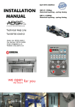
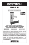
Parts
Shaft & Bushing
Kits
2
1
1) Shaft
2) Bushing
TABLE 5.0 SHAFT KITS
EATON
KIT
NUMBER
EATON
PRODUCT
CODE
EATON
DISPLACEMENT
CODE
EATON
SHAFT
CODE
9900332-001
9900332-002
BAF
BAF
Pos. 4,5,6
11
11
Pos. 8,9
-20
-01
14 Tooth w/ 20 splined shaft Metric
20mm Straight keyed shaft Metric
9900332-003
9900332-004
BAF
BAF
020 & 030
020 & 030
-25
-02
18 Tooth w/25 splined shaft
25mm Straight keyed shaft
Metric
Metric
9900332-005
9900332-006
BAF / BAV
BAF / BAV
040, 044 & 055
040, 044 & 055
-30
-03
14 Tooth w/30 splined shaft
30mm Straight keyed shaft
Metric
Metric
9900332-007
9900332-008
BAF / BAV
BAF / BAV
75
75
-35
-04
16 Tooth w/35 splined shaft
35mm Straight keyed shaft
Metric
Metric
9900332-009
9900332-010
BAF / BAV
BAF / BAV
087 & 108
087 & 108
-40
-05
18 Tooth w/40 splined shaft
40mm Straight keyed shaft
Metric
Metric
9900332-011
9900332-012
BAF / BAV
BAF / BAV
161
161
-45
-06
21 Tooth w/45 splined shaft
45mm Straight keyed shaft
Metric
Metric
9900332-013
9900332-014
BAF / BAV
BAF / BAV
225
225
-50
-07
24 Tooth w/50 splined shaft
50mm Straight keyed shaft
Metric
Metric
9900332-015
9900332-016
BAF / BAV
BAF / BAV
020 & 030
020 & 030
-12
-08
13 Tooth splined shaft
7/8 Straight keyed shaft
SAE
SAE
9900332-017
9900332-018
BAF / BAV
BAF / BAV
040, 044 & 055
040, 044 & 055
-14
-09
14 Tooth splined shaft
1 1/4 Straight keyed shaft
SAE
SAE
9900332-019
9900332-020
BAF / BAV
BAF / BAV
75
75
-13
-11
13 Tooth splined shaft
1 3/4 Straight keyed shaft
SAE
SAE
9900332-021
9900332-022
BAF / BAV
BAF / BAV
087 & 108
087 & 108
-13
-11
13 Tooth splined shaft
1 3/4 Straight keyed shaft
SAE
SAE
9900332-023
9900332-024
BAF / BAV
BAF / BAV
161
161
-13
-11
13 Tooth splined shaft
1 3/4 Straight keyed shaft
SAE
SAE
9900332-025
9900332-026
BAF / BAV
BAF / BAV
225
225
-13
-11
13 Tooth splined shaft
1 3/4 Straight keyed shaft
SAE
SAE
8
EATON Bent Axis Motors Parts and Repair E-MOPI-TS003-E February 2005
SHAFT DESCRIPTION
TYPE
Disassembly
When disassembling or assembling any Bent Axis piston
motor we recommend you choose an ideal workplace.
The work area must be clean and free of airborne
contaminants.
Clean parts which have been disassembled, use clean
solvents and appropriate tools which have been previously
cleaned. Use new, clean and threadless rags to handle and
dry parts. Remove the shaft seal following the procedure for
your type of seal.
Note: Thoroughly clean the exterior of the unit and
around stationary seal assembly before
disassembly. Make sure all open ports are sealed.
Step 1
Mark housing and cover so that they may be matched up
later during assembly.
NOTE: See page 5 for different end cover types.
Step 2
FIG 1.
Remove the end cover bolts.
MOTOR
BAF 20/30
BAF 40/55
BAF 75
BAF 90/108
BAF 161
BAF 225
WRENCH SIZE
(mm)
6
8
10
10
10
12
FIG 2.
EATON Bent Axis Motors Parts and Repair E-MOPI-TS003-E February 2005
9
Disassembly
Step 3
Remove the end cover, gasket and valve plate.
FIG 3.
Step 4
Remove retaining ring using appropriate pliers.
FIG 4.
Step 5
Pry off seal cover and shims with using two
screwdrivers.
FIG 5.
10
EATON Bent Axis Motors Parts and Repair E-MOPI-TS003-E February 2005
Disassembly
Step 6
Assemble the motor on the shaft puller. Secure it with two
screws on opposite ends of the square flange. Screw
threaded pin A on the shaft.
FIG 6.
Step 7
Remove rotating kit from the housing by turning the shaft
puller handle. Use your other hand to guide the cylinder barrel
during removal to avoid contact with the housing.
FIG 7.
Step 8
Mark cylinder barrel, shaft and retaining plate in a line with each
other. This will be used as a match mark for alignment during
the assembly process.
FIG 8.
EATON Bent Axis Motors Parts and Repair E-MOPI-TS003-E February 2005
11
Disassembly
Step 9
Remove cylinder barrel, Belleville washers and shims (as
required).
FIG 9.
Step 10
Using an allen key, remove screws which attach the
retaining plate.
MOTOR
BAF 20/30
BAF 44/55
BAF 75
BAF 90/108
BAF 161
BAF 225
WRENCH SIZE
MM
5
4
5
5
5
6
FIG 10.
12
EATON Bent Axis Motors Parts and Repair E-MOPI-TS003-E February 2005
Disassembly
Step 11
Remove retaining plate with pistons.
FIG 11.
Step 12
Use a permanent fine point pen to label the retaining plate
and pistons with corresponding location numbers. This will
ensure correct placement when they are reassembled.
Carefully separate pistons, starting from the index mark on
the retaining plate, and neatly place them down according to
disassembly order.
FIG 12.
Step 13
With appropriate pliers, remove the retaining ring, spacer and
shims. Once this is completed, remove bearings.
Once that you have disassembled the unit, check status of
individual parts, carefully following the steps described in the
next section.
FIG 13.
EATON Bent Axis Motors Parts and Repair E-MOPI-TS003-E February 2005
13
Check Condition
of Parts
Valve Plate
Check valve plate (item 3) protrusion out of the housing (see
page 44, Critical Dimensions). If the distance measured is
slightly less than normal requirements, replace Belleville
washers. If, there is no protrusion or the valve plate is
recessed in housing, this may indicate the following:
A) Excessive wear of distributor spherical surfaces or
cylinder barrel.
B) Yield of Belleville washers. (Does not apply to coil spring
design.)
C) End Cover deformation.
Inspect other internal components for damage.
FIG 1.
Seal Cover
Remove O-ring and shaft seal from cover and check wear.
Signs of excessive wear or seal extrusion may indicate excessive case pressure. (Pressure should not exceed 35 psi - 2.5
bar).
Note: Replace all seals when servicing motors.
FIG 2.
Cylinder Barrel
Inspect Sealing face of cylinder barrel for raised edges, wear
or smearing of material.
FIG 3.
14
EATON Bent Axis Motors Parts and Repair E-MOPI-TS003-E February 2005
Check Condition
of Parts
Piston
Inspect spherical base of the pistons and their seats on the
shaft, the piston surface and the piston bores surface.
TABLE 6.0 PISTON PARTS
DISPLACEMENT
(CM3)
DIM A(mm)
20
30
40
55
75
90
108
160
226
16
16
20
20
22
25
25
28.7
32
+0
-0.005
+0
-0.005
-0.020
-0.025
-0.020
-0.025
+0
-0.005
+0
-0.005
+0
-0.005
+0
-0.005
-0.020
-0.025
DIM B(mm)
DIM C(mm)
DIM D(mm)
0.02 ÷ 0.10
0.02 ÷ 0.10
0.02 ÷ 0.10
0.02 ÷ 0.10
0.02 ÷ 0.10
0.02 ÷ 0.10
0.02 ÷ 0.10
0.02 ÷ 0.08
0.02 ÷ 0.10
0.80 ÷ 0.90
0.80 ÷ 0.90
1.00 ÷ 1.16
1.00 ÷ 1.16
0.29 ÷ 0.59
0.51 ÷ 0.65
0.51 ÷ 0.65
0.96 ÷ 1.10
1.38 ÷ 1.578
16
16
20
20
22
25
25
28.7
32
+0
-0.005
+0
-0.005
-0.020
-0.025
-0.020
-0.025
+0
-0.005
+0
-0.005
+0
-0.005
+0
-0.005
-0.020
-0.025
FIG 4.
PART IDENTIFICATION
A = Piston rod diameter
B = Piston-rod axial end float
C = Rod rotation (Max)
D = Piston bore diameter
Bearings
Inspect bearings. Replace where there is excessive
clearance or pitting on race. Check bearing pockets in
housing for wear.
FIG 5.
EATON Bent Axis Motors Parts and Repair E-MOPI-TS003-E February 2005
15
Assembly
Step 1
Lubricate shaft with petroleum jelly, slip in bearing, spacer and
bearing. Use appropriate tool and rubber mallet to drive into place.
FIG 1.
Step 2
Assemble the spacer, the shims and the retaining ring. Ensure the
bearings are free to rotate without any axial movement on the
shaft. Add additional shims as required.
FIG 2.
Step 3
To ensure there is no axial movement, place a dial indicator on the
outer bearing race. Axial movement should read between + 0.005
and 0.08 mm.
Note: Hold shaft stationary during measurement
FIG 3.
16
EATON Bent Axis Motors Parts and Repair E-MOPI-TS003-E February 2005
Assembly
Step 4
Install seven pistons into the retaining plate using the
corresponding numbered pockets for correct placement and
original assembly order.
FIG 4.
Step 5
Secure pistons and retaining plate on shaft in original marked
position. Pour two drops of Loctite 242 on every retaining
plate screw.
FIG 5.
Step 6
Tighten screws on retaining plate to shaft assembly using
allen key.
FIG 6.
EATON Bent Axis Motors Parts and Repair E-MOPI-TS003-E February 2005
17
Assembly
Step 7
Ensure the two-piece pistons can rotate and move freely in any
direction.
FIG 7.
Step 8.
Install shims, Belleville washers (as required) and center pivot
into cylinder barrel. Match up alignment marks created before
disassembly.
Lubricate pistons and insert into cylinder barrel. Align
Match marks created during disassembly.
FIG 18.
Step 9.
Verify the cylinder barrel may pivot laterally as shown in
figure 9.
FIG 9.
18
EATON Bent Axis Motors Parts and Repair E-MOPI-TS003-E February 2005
Assembly
Step 10
Secure housing in the bench vice and lubricate bearing seats
with petroleum jelly.
FIG 10.
Step 11
Insert the rotating kit into the housing, turning the handle
gradually until it is fully seated.
FIG 11.
Step 12
Assemble cover, shaft seal, o-ring and shims (see tables page
42). Then secure with the retaining ring.
FIG 12.
EATON Bent Axis Motors Parts and Repair E-MOPI-TS003-E February 2005
19
Assembly
Step 13
Attach the shaft puller rod onto the shaft and pull the shaft
bearing out against the retaining ring.
FIG 13.
Step 14
Lubricate the spherical surface of the valve plate, then
assemble it with the cylinder barrel/housing. Verify the shaft
can’t turn freely in housing.
Note: Also make sure that the hole for pin 1 is set aligned to
the vertical center line of the casing.
FIG 14.
Step 15
Check that valve plate sits slightly higher than housing. The distance
measured between the two should be as follows (applies to Belleville
spring design only).
DISPLACEMENT
BAF 20/30
BAF 44/55
BAF 75
BAF 90/108
BAF 161
BAF 225
DISTANCE
(mm)
1.3 +1.5
1.3 +1.5
1.3 +1.5
1.4 +1.6
1.5 +1.7
1.5 +1.7
FIG 15.
20
EATON Bent Axis Motors Parts and Repair E-MOPI-TS003-E February 2005
Assembly
Step 16
Install gasket, assemble end cover and tighten screws and
torque according to requirements in table shown below.
TABLE 7.0 BAF END COVER BOLT
TIGHTENING TORQUE VALUES
BOLT
M8
M10
M12
M14
Torque (Nm)
2.5
5.0
8.5
13.5
FIG 16.
TABLE 7.1 BAV MOTOR CONTROL
BOLT TORQUE VALUES
POS.
BAV 55
BAV 75
BAV 108
BAV 161
BAV 225
Bolt
M 14x45 - 8.8
M 16x50 - 8.8
M 18x60 - 8.8
M 18x60 - 8.8
M 20x60 - 12.9
1
(12 N-m)
(18 N-m)
(26 N-m)
(26 N-m)
(40 N-m)
Bolt
M 10x35 - 8.8
M 10x35 - 8.8
2
(5 N-m)
(5 N-m)
Plug
G 1/8” - 8.8
G 1/8” - 8.8
G 1/8” - 8.8
G 1/8” - 8.8
G 1/8” - 8.8
3
(3 N-m)
(3 N-m)
(3 N-m)
(3 N-m)
(3 N-m)
Bolt
M 8x35 - 12.9
M 10x30 - 12.9 M 10x30 - 12.9
M 12x30 - 12.9
M 12x30 - 12.9
4
(4 N-m)
(7 N-m)
(7 N-m)
(12 N-m)
(12 N-m)
Bolt
M 10x35 - 8.8
M 12x40 - 8.8
M 12x40 - 8.8
M 14x45 - 8.8
M 14x45 - 8.8
5
(4 N-m)
(8 N-m)
(8 N-m)
(12 N-m)
(12 N-m)
Plug
G 1/4” - 8.8
G 1/4” - 8.8
G 1/4” - 8.8
G 1/4” - 8.8
G 1/4” - 8.8
6
(4 N-m)
(4 N-m)
(4 N-m)
(4 N-m)
(4 N-m)
Bolt
M 8x65 - 12.9
M 10x70 - 12.9 M 10x70 - 12.9
M 12x70 - 12.9
M 12x70 - 12.9
7
(4 N-m)
(7 N-m)
(7 N-m)
(12 N-m)
(12 N-m)
Bolt
M 8x16 - 45H
M 8x16 - 45H
M 8x16 - 45H
M 8x16 - 45H
M 8x16 - 45H
8
(3.5* N-m)
(3.5* N-m)
(3.5* N-m)
(3.5* N-m)
(3.5* N-m)
Bolt
M 8x8 - 45H
M 8x8 - 45H
M 8x8 - 45H
M 8x8 - 45H
M 8x8 - 45H
9
(2.5* N-m)
(2.5* N-m)
(2.5* N-m)
(2.5* N-m)
(2.5* N-m)
10 The tightening torque of caps, plugs and fittings must be comprised between 4 and 7 daNm
*Add Loctite 243
EATON Bent Axis Motors Parts and Repair E-MOPI-TS003-E February 2005
21
Installation Guidelines
NOTE: For dimensions and porting reference see dimensions
section axial piston catalogue.
The following installation guidelines for Eaton Bent Axis
piston motors are designed for standard components applied
within catalog ratings. Observing these guidelines below will
help ensure acceptable life of the motors.
1. Filling the Case
The case of bent axis piston motors must be pre-filled with
hydraulic oil before the system is started for the first time.
Use the case drain connection at the highest point to ensure
the case remains full at all times. See figure 1.
Caution: Starting the motor with little or no oil in the
case causes immediate and permanent damage
to the piston unit.
2. Connections
To reduce noise levels, flexible hoses are recommended
(Main system pressure lines as well as case drain lines).
Case drain hoses should be as short as possible.
Minimize pressure drops due to couplings, elbows and
differences in diameter.
Where non-flexible tubes are used, ensure that the pipes do
not pull on the cover of the motor.
All hoses connected to tank (case drain lines) should be
immersed at least 200 mm [8 in.] below the minimum oil
level and at least 150 mm [6 in.] from the bottom of the tank.
Drive Shaft
Take special care to ensure that mechanical parts of the
motor are coupled correctly. Ensure that the shaft and flange
are lined up accurately to prevent additional loads on the
shaft bearings. Flexible couplings should be used.
Caution: Incorrectly aligned parts significantly reduce the
service life of the bearings.
22
EATON Bent Axis Motors Parts and Repair E-MOPI-TS003-E February 2005
Installation Guidelines
Installation position
Motors may be installed both above and below the level of
the fluid in the tank, (lowest level of the oil when the system
is operating). When motors are used in open circuit applications, the oil level is affected by the number and size of any
hydraulic cylinders used in the system. For mobile installations
it is important to take into account the slope of the ground
and the effect of centrifugal forces on the oil level.
Installation above the tank
Particular care should be taken when installing units above
the tank. Special case drain hoses must always be used to
prevent the case from being siphoned out.
Always use the highest case drain port available and ensure
that the line is designed such that the motor case remains
full at all times.
It is recommended to position a pre-loaded check valve in the
cased drain line (maximum pressure when open: 0.5 bar [8
psi]) to prevent oil from draining from the motor case when
the system is not in use
The oil level of the units should be checked at regular intervals. It is essential to check the level if the system is out of
service for extended periods of time, since the force of
gravity causes oil to drain from the case.
Installation below the tank
Installation below the minimum level of the fluid (or immersed in
fluid) does not create particular problems.
Gearbox mount motors should not be installed vertically with
the shaft oriented upwards.
Flushing
If Bent Axis piston motors are to be installed with shaft turned
upwards, or run at high oil temperature inside the tank (>50ΥC),
or if units are used for a long operation time at high
pressures (>250 bar), it is recommended to flush motor/pump
bearings, by using oil at equal or lower temperature than the
tank. Flush the bearings through Port E
System Start-up
Before starting system for the first time, fill system components
with new and filtered oil. In addition, clean the reservoir and fill
with the same type of oil. We recommend flushing the circuit.
Verify that charge pressure is correct (closed circuits). Check
reservoir level and top-off if necessary.
Figure 3
23
EATON Bent Axis Motors Parts and Repair E-MOPI-TS003-E February 2005
Controls
Technical Data
TABLE 8.0
MAXIMUM DISPLACEMENT
PERFORMANCE SPECIFICATIONS
Model
Vgmax
[cm3/rev]
Qmax (*)
[l/min]
Q drain (Max)
[l/min]
ηv (Max)
N Target
Speed at 250 bar
BAV 55
54.83
54.8
min 96%
2500 rpm
BAV 75
75.3
75.3
min 96%
2500 rpm
BAV108
107.5
107.5
min 96%
2500 rpm
BAV161
160.8
160.8
min 96%
2200 rpm
BAV 225
225.1
225.1
min 0.5
max 1.5
min 0.7
max 2
min 1
max 2.7
min 1.3
max 3.5
min 1.6
max 4.5
min 96%
1800 rpm
(*): 1000 rpm, 40 bar
MINIMUM DISPLACEMENT
PERFORMANCE SPECIFICATIONS
Model
Vgmin
[cm3/rev]
Qmin (*)
[l/min]
Q drain (Min)
[l/min]
ηv (Min)
N Target
Speed at 250 bar
BAV 55
15.8
15.8
min 94%
3000 rpm
BAV 75
21.7
21.7
min 94%
3000 rpm
BAV108
30.9
30.9
min 94%
3000 rpm
BAV161
46.2
46.2
min 94%
2500 rpm
BAV 225
64.8
64.8
min 0.5
max 1.5
min 0.7
max 2
min 1
max 2.7
min 1.3
max 3.5
min 1.6
max 4.5
min 94%
2500 rpm
(*): 1000 rpm, 40 bar
Table Definitions
Vgmax - Maximum Motor Displacement
Vgmin - Minimum Motor Displacement
Qmax - Test flow for setting maximum motor displacement
Qmin - Test flow for setting minimum motor displacement
Qdrain(max) - Case flow at maximum displacement, target speed, and pressure
Qdrain(min) - Case flow at minimum displacement, target speed, and pressure
ηv(max) - Volumetric efficiency at 250 bar and max displacement
ηv(min) - Volumetric efficiency at 250 bar and min displacement
N - Target Speed
24
EATON Bent Axis Motors Parts and Repair E-MOPI-TS003-E February 2005
Testing Procedures
BAV Controls
Motor setup for Testing “BAV” Variable Displacement
Bent Axis Motors
1. Obtain the proper shaft coupling for the motor.
2. Clean the motor front flange of oil and/or dirt to facilitate
evaluation of oil leakage from shaft seal after test.
3. Assemble the coupling on the motor shaft.
4. Mount the motor on the test stand.
5. Connect the high pressure lines to the main supply
ports “A” and “B” of the motor.
6. Connect a case drain line to ports "C” or “D" port on
motor housing (see table 8.0 ). Install a flow meter in
case drain line to monitor.
7. Motor housing must be filled with oil before starting the
test. Reference page 22 for instructions.
8. During testing should the system pressure fall below 40
bar, boost the control via Y1 port.
9. Initial run-in of the motor must be done at 500 rpm in
both directions of rotation at pressures from 0 to 100
bar.
10. Continue with test procedure specific to appropriate
control.
Before Proceeding with any control adjustments check
the following:
1.
2.
3.
Review/read through all instructions before starting the
procedures.
Verify on order form desired displacement limitations of
the motor.
Break-in of the motor must be done at 500 rpm, half in
one rotation direction and half in the other, with
pressure from 0 to 100 bar on all controls, except
pressure response with adjustable hydraulic override
(Biased to minimum displacement), a run-in pressure
from 40 to 100 bar (X2 pressure 0 bar) is recommended.
Procedures for specific controls are located on the following pages:
Page
EA & EC (Electric Proportional Control Biased to Maximum Displacement) . . . . . . . . . . . . . . . . . . . . . . . . . . . . . . . . . . . . .27
EB & ED (Electric Proportional Control Biased to Minimum Displacement) . . . . . . . . . . . . . . . . . . . . . . . . . . . . . . . . . . . . . .28
HA Hydraulic Proportional Control (Biased to maximum displacement) . . . . . . . . . . . . . . . . . . . . . . . . . . . . . . . . . . . . . . . .29
HB Hydraulic Proportional Control (Biased to minimum displacement) . . . . . . . . . . . . . . . . . . . . . . . . . . . . . . . . . . . . . . . . .30
H1 Hydraulic Two-Position Control (Biased to maximum displacement) . . . . . . . . . . . . . . . . . . . . . . . . . . . . . . . . . . . . . . . . .31
H2 Hydraulic Two-Position Control (Biased to minimum displacement) . . . . . . . . . . . . . . . . . . . . . . . . . . . . . . . . . . . . . . . . .32
M1 Manual Control (Biased to maximum displacement) . . . . . . . . . . . . . . . . . . . . . . . . . . . . . . . . . . . . . . . . . . . . . . . . . .33-34
M2 Manual Control (Biased to minimum displacement) . . . . . . . . . . . . . . . . . . . . . . . . . . . . . . . . . . . . . . . . . . . . . . . . . . . .35
PA Pressure Response Control (Biased to minimum displacement) . . . . . . . . . . . . . . . . . . . . . . . . . . . . . . . . . . . . . . . . .36-37
PB Pressure Response Control with Adjustable Hydraulic Override
(Biased to minimum displacement) . . . . . . . . . . . . . . . . . . . . . . . . . . . . . . . . . . . . . . . . . . . . . . . . . . . . . . . . . . . . . . . . . .38-39
E5” and “E6” Two-position electrical control with Pressure Response Control with
Adjustable Hydraulic Override (Biased to maximum displacement) . . . . . . . . . . . . . . . . . . . . . . . . . . . . . . . . . . . . . . . . .40-41
EATON Bent Axis Motors Parts and Repair E-MOPI-TS003-E February 2005
25
Testing Procedures
Control Options EA & EC
(Electric Proportional Control Biased
to Maximum Displacement)
BAV Motor Adjustment & Port Locations
(1) Mounting Holes
(2) Case Drain Port
(3) High Pressure Ports
(4) Air Bleed Port
(5) MAX/MIN
DISPLACEMENT
SETTING SCREW
VARIATION EACH
DISPLACEMENT
METRIC
SAE
METRIC SAE
METRIC
SAE
METRIC
SAE
SCREW TURN
BAV 55
BAV 75
BAV 108
BAV 161
BAV 225
Ø 13
Ø 14
Ø 17
Ø 18
Ø 22
Ø 14.3
Ø 20.6
Ø 20.6
Ø 20.6
Ø 20.6
G 1/2”
G 1/2”
G 1/2”
G 1/2”
G 3/4”
3/4” SAE 6000
1” SAE 6000
1” SAE 6000
1”1/4 SAE 6000
1”1/4 SAE 6000
3/4” SAE 6000
1” SAE 6000
1” SAE 6000
1”1/4 SAE 6000
1”1/4 SAE 6000
G 1/8”
G 1/8”
G 1/8”
G 1/8”
G 1/8”
7/16” - 20 UNF
7/16” - 20 UNF
7/16” - 20 UNF
7/16” - 20 UNF
7/16” - 20 UNF
1.4 cm3/rev
2 cm3/rev
2.6 cm3/rev
4 cm3/rev
5 cm3/rev
26
1”1/16-12 UN 2B
1”1/16-12 UN 2B
1”1/16-12 UN 2B
1”1/16-12 UN 2B
1”3/16-12 UN 2B
EATON Bent Axis Motors Parts and Repair E-MOPI-TS003-E February 2005
Testing Procedures
Control Options EA & EC
(Electric Proportional Control Biased
to Maximum Displacement)
1.
Check/set MAXIMUM DISPLACEMENT (no load).
Unscrew the maximum displacement adjustment screw.
Unscrew the four solenoid screws and remove the
solenoid and spacer from the control housing interface.
Remove the pin and unscrew the lock nut. Unscrew the
pilot-pushing screw until the motor is swiveled to
maximum displacement. Set the flow rate according to
the value reported on table 8.0 on page 24: the oil flow
rate (in l/min.) must be set to the motor displacement
numerical value (cm3/rev. (Example: Maximum 160
cm3/rev motor requires flow rate of 160 l/min). Adjust
the displacement screw until the motor is running at
1000 rpm.
2.
Lock the adjustment screw with nut and locking nut
(with their two washers).
3.
Check/set MINIMUM DISPLACEMENT (no load). Turn
the pilot-pushing screw until the control swivels the
motor to the maximum displacement. Set the oil flow
rate according to the value reported on table 8.0 (see
page 24), the numerical value of the oil flow rate (in
l/min.) must be set to the motor displacement numerical
value (in cm3/turn). (Example: Minimum displacement
setting of 60 cm3/rev requires flow rate of 60 l/min).
Adjust the displacement setting screw until the motor is
running at 1000 rpm.
4.
Lock the adjustment screw with nut and locking nut
(with their two washers).
5.
Turn the pilot-pushing screw CCW until the control
starts to swivel the motor to the minimum displacement, then an additional one half turn CCW. Turn the
locking grub screw on to lock the pilot-pushing screw.
6.
Insert the solenoid pin into its seat. Check that the
distance between the pin end and the outer flat of the
interface is 4.5 mm ± 0.2 mm. If this is not adjusted correctly, it will affect the control operation.
9.
Solenoid input current range is 250 - 650 mA (BAV 55,
75, 108) or 300 - 700 mA (BAV 160, 226). Verify the
control operation by starting at maximum displacement
and biasing the motor toward minimum displacement
and vice versa. Speed/displacement variation should be
proportional to the input current and stepless. Verify control function two or three times by varying the input current at 0 bar working pressure and changing the direction of motor rotation. A small hysteresis is normal.
10. Measure motor leakage and volumetric efficiencies at
maximum displacement conditions. Use the procedure
as per step 8 using a system pressure of 250 bar and
motor input flows to achieve the target speed listed in
table 8.0 (see page 24).
11. Check the CASE DRAIN OIL FLOW RATE at MAX DISP.
The acceptable values are listed in table 8.0 on
page 24. This test must be done in both the directions
of rotation. Use the higher case flow rate and record for
comparison to specifications.
12. Check the CASE DRAINAGE OIL FLOW RATE at
MINIMUM DISP. Increase the input current until the control swivels the motor to minimum displacement. The
acceptable value of case drain flow rates are
reported on table 8.0 (see page 24). This test should
also be done in both the directions of rotation. Use the
higher case flow rates for comparison to specifications.
13. Check the VOLUMETRIC EFFICIENCY (250 bar working
pressure) at maximum and minimum displacement with
the following formula:
Vg = motor displacement (cm3/rev)
n = speed (rpm)
Q = flow (l/min)
WARNING: The pin must be free to move into its seat. If not,
disassemble the solenoid interface, remove the pin and
bore the pin's seat. Once this has been done the pin
should move freely. Reassemble the solenoid
interface and the pin. Repeat setting procedure from
point 1.
14. Check for oil leaks. Stop the motor.
7.
Mount the solenoid and the spacer on the interface.
Tighten the screws at 0.5 daNm Max.
15. Record the motor test data as required.
8.
Set the solenoid input current to 250 mA (BAV 55, 75,
108) or 300 mA (BAV 160, 226). Using the control current starting adjustment screw, turn it until the control
starts to swivel the motor. Lock the control current
adjustent screw with nut and locking nut.
The test results must not fall below the published data
in table 8.0 on page 24.
EATON Bent Axis Motors Parts and Repair E-MOPI-TS003-E February 2005
27
Testing Procedures
Controls EB & ED (Electric Proportional
Control Biased to Minimum Displacement)
1.
Check/set MINIMUM DISPLACEMENT (no load).
Unscrew the minimum displacement adjustment screw.
Unscrew the four solenoid screws and remove the
solenoid and spacer from the interface. Remove the pin
and unscrew the locking nut. Unscrew the pilot-pushing
screw until the motor is swiveled to the minimum
displacement. Set the flow rate according to the value
reported on table 8.0 (see page 24): the numerical value
of the oil flow rate (in l/min.) must be set to the motor
displacement numerical value (in cm3/turn). Adjust
the displacement screw until the motor is running at
1000 rpm.
2.
Lock the adjustment screw with nut and locking nut
(with their two washers).
3.
Check/set MAXIMUM DISPLACEMENT (no load). Turn
the pilot-pushing screw until the control swivels the
motor to the maximum displacement. Set the oil flow
rate according to the value reported on table 8.0 on
page 24: the numerical value of the oil flow rate (in
l/min.) must be set to the motor displacement numerical
value (in cm3/turn). Adjust the displacement setting
screw until the motor is running at 1000 rpm.
4.
Lock the said adjustment screw with nut and cap nut
(with their two washers).
5.
Turn the pilot-pushing screw until the control starts to
swivel the motor to the maximum displacement, then
unscrew it one half turn. Rotate the locking grub screw
to lock the pilot-pushing screw.
6.
Insert the pin into its seat. Check that the distance
between the pin's end and the outer flat of the interface
is 4.5 mm ± 0.2 mm. Restore it to this measurement,
as this would affect the control operation.
WARNING: The pin must be free to move in its seat; if this is
not, disassemble the solenoid interface, remove the pin
and bore the pin's seat. Once this has been done the
pin should move freely. Reassemble the solenoid interface and pin. Repeat setting procedure from point 1.
7.
Fit the solenoid on the interface. Tighten the screws
with 0.5 daNm Max.
8.
Set solenoid input current to 250 mA (BAV 55, 75, 108)
or 300 mA (H2V 160, 226). Turn the control current
starting setting screw until the control starts to swivel
the motor. Lock the control current adjustment screw
with nut and locking nut.
9.
Solenoid input current range is 250 - 650 mA (H2V 55,
75, 108) or 300 - 700 mA (H2V 160, 226). Check the
control operation, starting from minimum displacement
towards the maximum displacement and vice versa. This
variation should
be proportional to the input current
and step less. Check the control’s operation two or
three times, varying the input current both increasing
and decreasing it, with 0 bar working pressure and
changing the direction of rotation. A small hysteresis
is normal.
10. Using an appropriate solvent, clean oil traces from the
motor. Check for oil leaks during the following high
pressure test.
11. Measure motor leakage and volumetric efficiencies at
maximum displacement conditions. Use the procedure
as per step 9 using a system pressure of 250 bar and
motor input flows to achieve the target speed listed in
table 8.0 (see page 24).
12. Check the DRAINAGE FLOW RATE at MAXIMUM DISP.
The acceptable value is reported on table 8.0. This test
must be done in both rotation directions. Report the
highest flow rate in each direction on the test form.
13. Check the DRAINAGE FLOW RATE at MINIMUM DISP.
250 bar, 3000 rpm. Increase the input current until the
control swivels the motor to the maximum displacement. The acceptable value of drainage flow rates is
reported on table 8.0, (see page 24). This test must be
done in both the directions of rotation. Report the
highest flow rate in each direction on the test form.
14. Check the VOLUMETRIC EFFICIENCY (250 bar working
pressure) at maximum and minimum displacement with
the following formula:
Vg = motor displacement (cm3/rev)
n = speed (rpm)
Q = flow (l/min)
The obtained data must not fall below the data in table
8.0 on page 24.
15. Check for oil leaks. Stop the motor.
16. Fill the motor test form with the required data.
28
EATON Bent Axis Motors Parts and Repair E-MOPI-TS003-E February 2005
Testing Procedures
Control Option HA
Hydraulic Proportional Control
(Biased to Maximum Displacement)
1.
Increase the motor working pressure to at least
40 bar.
2.
Check/set MAXIMUM DISPLACEMENT (working pressure at least 40 bar). Unscrew the control starting
adjustment screw. Set the X2 port piloting pressure at
0 bar. Set the numerical value of the input flow rate (in
l/min.) same as the motor displacement numerical value
(in cm3/rev) (see table 8.0 on page 24). Adjust the
displacement screw until the motor is running at 1000
rpm.
3.
Lock the adjustment screw with nut and locking nut
(with their two washers).
4.
Check/set MINIMUM DISPLACEMENT (working pressure at 40 bar). Put to 8 – 9 bar the X2 port piloting
pressure. Turn the control starting adjustment screw
until the control swivels the motor to the minimum displacement. Unscrew 1/4-1/2 turn. Lock the adjustment
screw with nut and cap nut (with their two washers).
5.
Increase the X2 port piloting pressure until the control
swivels the motor to the minimum displacement. Set
the oil flow rate according to the value reported on table
8.0 (see page 24). Adjust the minimum displacement
setting screw until the motor is running at 1000 rpm.
The numerical value of the oil flow rate (in l/min.) must
be set to the motor displacement numerical value (in
cm3/rev). The minimum displacement adjustment screw
must then be adjusted until the motor is running at 1000
rpm.
6.
Lock the adjustment screw with nut and cap nut (with
their two washers).
7.
By varying the X2 port piloting pressure, check the
maximum and minimum displacement just set. Any
difference with the expected values must be corrected
repeating the procedure from point 4 to point 7.
8.
Check the HYDRAULIC PILOTING STARTING AND
ENDING PRESSURES. The standard setting field is
6 - 18 bar. The gap between minimum and maximum
piloting pressure must not be less than 10 bar. Check
the control stability with intermediate hydraulic piloting
pressures. Check that the control can always reach the
pre-set maximum and minimum displacements. The
hydraulic piloting starting and ending pressures must be
recorded on test form.
9.
Using an appropriate solvent, check for oil leaks and
clean the motor during the following high pressure test.
10. Measure motor leakage and volumetric efficiencies at
maximum displacement conditions. Use the procedure
as per step 8 using a system pressure of 250 bar and
motor input flows to achieve the target speed listed in
table 8.0 (see page 24).
11. Check the DRAIN FLOW RATE at MAXIMUM DISP. The
acceptable value is reported on table 8.0. This test must
be done in both rotation directions. Report the highest
flow rate in each direction on the test form.
12. Check the DRAIN FLOW RATE at MINIMUM DISP.
Increase the piloting pressure on X2 port until the
control swivels the motor to the minimum displacement. The acceptable value is reported on table 8.0, (see
page 24). This test must be done in both rotation directions. Report the highest flow rate in each direction on
the test form.
13. Check the VOLUMETRIC EFFICIENCY (250 bar working
pressure) at maximum and minimum displacement with
the following formula:
Vg = motor displacement (cm3/rev)
n = speed (rpm)
Q = flow (l/min)
The obtained data must not fall below the data in table
8.0 on page 24.
14. Check for oil leaks. Stop the motor.
15. Fill the motor test form with the required data.
EATON Bent Axis Motors Parts and Repair E-MOPI-TS003-E February 2005
29
Testing Procedures
Control Option HB
Hydraulic Proportional Control
(Biased to Minimum Displacement)
1.
Increase the motor working pressure to at least 40 bar.
2.
Check/set MINIMUM DISPLACEMENT (Working pressure at least 40 bar). Unscrew the control starting
adjustment screw. Set the X2 port piloting pressure to 0
bar. Set the numerical value of the input flow rate (in
l/min.) same as the motor displacement numerical value
(in cm3/rev) (see table 8.0 on page 24). Adjust the displacement screw until the motor is running at 1000 rpm.
3.
4.
5.
Lock the adjustment screw with nut and cap nut (with
their two washers).
Check/set MAXIMUM DISPLACEMENT (working pressure at least 40 bar). Set to 8 – 9 bar the X2 port piloting
pressure. Turn the control starting adjustment screw
until the control swivels the motor to the minimum displacement. Unscrew starting adjustment screw 1/4-1/2
turn. Lock the adjustment screw with nut and cap nut
(with their two washers).
Increase the X2 port piloting pressure until the control
swivels the pump to the maximum displacement. Set
the input flow rate according to the value reported on
table 8.0 (see page 24): Adjust the maximum displacement setting screw until the motor is running at 1000
rpm. The numerical value of the input flow rate (in l/min.)
must be set to the motor displacement numerical value
(in cm3/rev). The maximum displacement
adjustment screw must then be adjusted until the motor
is running at 1000 rpm.
maximum displacement conditions. Use the procedure
as per step 8 using a system pressure of 250 bar and
motor input flows to achieve the target speed listed in
table 8.0 (see page 24).
11. Check the DRAINAGE FLOW RATE at MINIMUM DISP.
The acceptable value is reported on table 8.0 (see page
24). This test must be done in both rotation directions.
Report the highest flow rate in each direction on the test
form.
12. Check the DRAIN FLOW RATE at MAXIMUM DISP.
Increase the piloting pressure until the control swivels
the motor to the maximum displacement. The acceptable value of drain flow rates is reported on table 8.0.
This test must be done in both rotation directions.
Report the highest flow rate in each direction on the test
form.
13. Check the VOLUMETRIC EFFICIENCY (250 bar working
pressure) at maximum and minimum displacement with
the following formula:
Vg = motor geometrical displacement (cm3/giro)
n = speed (rpm)
Q = flow (l/min)
6.
Lock the adjustment screw with nut and cap nut (with
their two washers).
7.
By varying the X2 port piloting pressure, check the maximum and minimum displacement just set. Any difference with the expected values must be corrected
repeating the procedure from point 4 to point 7.
14. Check for oil leaks. Stop the motor.
Check the HYDRAULIC PILOTING STARTING AND ENDING PRESSURES. Check the control starting and ending
pressure. Standard control pressure is 6 - 18 bar. The
gap between minimum and maximum necessary
piloting pressure must not be less than 10 bar. Check
the control stability with intermediate hydraulic piloting
pressures. Check that the control can always reach the
pre-set maximum and minimum displacements. The
hydraulic piloting starting and ending pressures must
be recorded on test form.
End test
1. Open the lower drainage port S on the motor casing.
8.
The obtained data must not fall below the data in
table 8.0 (see page 24).
15. Fill the motor test form with the required data.
2.
Remove the motor from the test bench.
3.
Check for oil leaks from the front cover and the shaft
seal.
9.
Using an appropriate solvent, check for oil leaks and
clean the motor during the following high pressure test.
10. Measure motor leakage and volumetric efficiencies at
30
EATON Bent Axis Motors Parts and Repair E-MOPI-TS003-E February 2005
Testing Procedures
Control Option H1
Hydraulic Two-Position Control
(Biased to Maximum Displacement)
1.
Check/set MAXIMUM DISPLACEMENT (no load). No
piloting pressure on X2 (Motor in maximum displacement). Set the flow rate according to the value reported
on table 8.0 (see page 24): the numerical value of the oil
flow rate (in l/min.) must be set to the motor
displacement numerical value (in cm3/ turn). Adjust the
displacement screw until the motor is running at 1000
rpm.
2.
Lock the adjustment screw with nut and locking nut
(with their two washers).
3.
Check/set MINIMUM DISPLACEMENT (no load). Set X2
port pressure at 30 bar (Motor in minimum
displacement). Set the oil flow rate according to the
value reported on table 8.0 (see page 24): the numerical
value of the oil flow rate (in l/min.) must be set to the
motor displacement numerical value (in cm3/turn). Adjust
the displacement setting screw until the motor is
running at 1000 rpm.
4.
Lock the adjustment screw with nut and locking nut
(with their two washers).
5.
Minimum control piloting pressure setting. Set piloting
pressure on X2 port at 15 bar. Turn the control starting
screw, turn it until the control swivels the motor. Lock
the screw into position with nut and locking nut.
6.
With 0 bar working pressure, check that the control
change from minimum to maximum displacement and
vice-versa when the piloting pressure X2 is switched.
This procedure must be done in both the directions of
rotation of the motor.
7.
Using an appropriate solvent, clean oil traces from the
motor. Check for any oil leaks during the following high
pressure test.
8.
Measure motor leakage and volumetric efficiencies at
maximum displacement conditions. Use the procedure
as per step 6 using a system pressure of 250 bar and
motor input flows to achieve the target speed listed in
table 8.0 (see page 24).
9.
Check the DRAINAGE FLOW RATE at MAX DISP.
Acceptable value is reported on table 8.0 (see page 24).
This test must be done in both rotation directions.
Report the highest flow rate in each direction on the test
form.
10. Check the DRAINAGE FLOW RATE at MIN DISP. To feed
X2 port until the control swivels the motor to the
minimum displacement. Acceptable value of drainage
flow rates is reported on table 8.0 (see page 24). This
test must be done in both rotation directions. Report the
highest flow rate in each direction on the test form.
11. Check the VOLUMETRIC EFFICIENCY (250 bar working
pressure) at maximum and minimum displacement with
the following formula:
Vg = motor displacement (cm3/rev)
n = speed (rpm)
Q = flow (l/min)
The obtained data must not fall below the data in table
8.0, on page 24.
12. Check for oil leaks. Stop the motor.
13. Fill the motor test form with the required data.
EATON Bent Axis Motors Parts and Repair E-MOPI-TS003-E February 2005
31
Testing Procedures
Control Option H2
Hydraulic Two-Position Control
(Biased to Minimum Displacement)
1.
Check/set MINIMUM DISPLACEMENT (no load). No
Piloting pressure on X2 (Motor in minimum displacement). Set the flow rate according to the value reported
on table 8.0 (see page 24): the numerical value of the oil
flow rate (in l/min.) must be set to the motor displacement numerical value (in cm3/ turn). Adjust the displacement screw until the motor is running at 1000 rpm.
2.
Lock the adjustment screw with nut and locking nut
(with their two washers).
3.
Check/set MAXIMUM DISPLACEMENT (no load). Set X2
port piloting pressure to 30 bar (Motor in maximum
displacement). Set the oil flow rate according to the
value reported on table 8.0 (see page 24): the numerical
value of the oil flow rate (in l/min.) must be set to the
motor displacement numerical value (in cm3/turn). Adjust
the displacement setting screw until the motor is
running at 1000 rpm.
4.
Lock the adjustment screw with nut and cap nut (with
their two washers).
5.
Minimum control piloting pressure setting. Set X2
piloting pressure to 15 bar. Turn the control starting
screw, until the control swivels the motor. Lock the
screw into position with nut and locking nut.
6.
With 0 bar working pressure, check that the control
change from minimum to maximum displacement and
vice-versa when the piloting pressure X2 is switched.
This procedure must be done in both the directions of
rotation of the motor.
7.
Using an appropriate solvent, clean the motor and check
for oil leaks during the following high pressure test.
8.
Measure motor leakage and volumetric efficiencies at
maximum displacement conditions. Use the procedure
as per step 6 using a system pressure of 250 bar and
motor input flows to achieve the target speed listed in
table 8.0 (see page 24).
32
9.
Check the DRAINAGE FLOW RATE at MIN DISP. The
acceptable value is reported on table 8.0. This test must
be done in both rotation directions. Report the highest
flow rate in each direction on the test form.
10. Check the DRAINAGE FLOW RATE at MAX DISP. To feed
X2 port until the control swivels the motor to the maximum displacement. Acceptable value of drainage flow
rates is reported on table 8.0 (page 24). This test must
be done in both the directions of rotation. Report the
highest flow rate in each direction on the test form.
11. Check the VOLUMETRIC EFFICIENCY (250 bar working
pressure) at maximum and minimum displacement with
the following formula:
Vg = motor displacement (cm3/rev)
n = speed (rpm)
Q = flow (l/min)
The obtained data must not fall below the data in table
8.0 on page 24.
12. Check for oil leaks. Stop the motor.
13. Fill the motor test form with the required data.
End test
1.
Open the lower drainage port S on the motor casing.
2.
Remove the motor from the test bench.
3.
Check for oil leaks from the front cover and the
shaft seal.
EATON Bent Axis Motors Parts and Repair E-MOPI-TS003-E February 2005
Testing Procedures
Control Option “M1” Manual
Control (Biased to Maximum
Displacement)
Control Option “M2” Manual
Control (Biased to Minimum
Displacement)
(1) Mounting Holes
(2) Case Drain Port
(3) High Pressure Ports
(4) Air Bleed Port
(5) MAX/MIN
DISPLACEMENT
SETTING SCREW
VARIATION EACH
DISPLACEMENT
METRIC
SAE
METRIC SAE
METRIC
SAE
METRIC
SAE
SCREW TURN
BAV 55
BAV 75
BAV 108
BAV 161
BAV 225
Ø 13
Ø 14
Ø 17
Ø 18
Ø 22
Ø 14.3
Ø 20.6
Ø 20.6
Ø 20.6
Ø 20.6
G 1/2”
G 1/2”
G 1/2”
G 1/2”
G 3/4”
3/4” SAE 6000
1” SAE 6000
1” SAE 6000
1”1/4 SAE 6000
1”1/4 SAE 6000
3/4” SAE 6000
1” SAE 6000
1” SAE 6000
1”1/4 SAE 6000
1”1/4 SAE 6000
G 1/8”
G 1/8”
G 1/8”
G 1/8”
G 1/8”
7/16” - 20 UNF
7/16” - 20 UNF
7/16” - 20 UNF
7/16” - 20 UNF
7/16” - 20 UNF
1.4 cm3/rev
2 cm3/rev
2.6 cm3/rev
4 cm3/rev
5 cm3/rev
1”1/16-12 UN 2B
1”1/16-12 UN 2B
1”1/16-12 UN 2B
1”1/16-12 UN 2B
1”3/16-12 UN 2B
EATON Bent Axis Motors Parts and Repair E-MOPI-TS003-E February 2005
33
Testing Procedures
Control Option M1
Manual Control (Biased to Maximum
Displacement)
1.
Check/set MAXIMUM DISPLACEMENT (motor
unloaded). Turn the hand wheel until the motor is at
the maximum displacement. Set the flow rate according
to the value reported on table 8.0 (see page 24): the
numerical value of the oil flow rate (in l/min.) must be
set to the motor displacement numerical value (in
cm3/turn). Turn the maximum displacement setting
screw until the motor turns at 1000 rpm.
2.
Lock the adjustment screw with nut and locking nut
(with their two washers).
3.
Check/set MINIMUM DISPLACEMENT (motor
unloaded). Turn the hand wheel until the motor is at the
minimum displacement. Set the flow rate according to
the value reported on table 8.0 (see page 24): the
numerical value of the oil flow rate (in l/min.) must be
set to the motor displacement numerical value (in
cm3/turn). Turn the minimum displacement setting screw
until the motor turns at 1000 rpm.
4.
5.
8.
Check the DRAINAGE FLOW RATE at MAXIMUM DISPLACEMENT. Turn the hand wheel until the motor is at
maximum displacement. Acceptable value is reported on
table 8.0 (see page 24). This test must be done in both
rotation directions. Report the highest flow rate in each
direction on the test form.
9.
Check the DRAINAGE FLOW RATE at MINIMUM
DISPLACEMENT. Turn the hand wheel until the motor is
at minimum displacement. Acceptable value is reported
on table 8.0 (see page 24). This test must be done in
both rotation directions. Report the highest flow rate in
each direction on the test form.
10. Check the VOLUMETRIC EFFICIENCY (250 bar working
pressure) at maximum and minimum displacement with
the following formula:
Lock the adjustment screw with nut and locking nut
(with their two washers).
With motor unloaded, check that the hand wheel control
changes the displacement motor from maximum
displacement to minimum displacement and vice-versa.
This procedure must be done in both the directions of
rotation of the motor.
6.
Using an appropriate solvent, check for oil leaks and
clean the motor during the following high pressure test.
7.
Measure motor leakage and volumetric efficiencies at
maximum displacement conditions. Use the procedure
as per step 5 using a system pressure of 250 bar and
motor input flows to achieve the target speed listed in
table 8.0 (see page 24).
Vg = motor displacement (cm3/rev)
n = speed (rpm)
Q = flow (l/min)
The obtained data must not fall below the data in table
8.0 (see page 24).
11. Check for any oil leaks. Stop the motor.
12. Fill the motor test form with the required data.
34
EATON Bent Axis Motors Parts and Repair E-MOPI-TS003-E February 2005
Testing Procedures
Control Option M2
Manual Control
(Biased to Minimum Displacement)
1.
Check/set MINIMUM DISPLACEMENT (motor
unloaded). Turn the hand wheel until the motor is at the
minimum displacement. Set the flow rate according to
the value reported on table 8.0 (see page 24): the
numerical value of the oil flow rate (in l/min.) must be
set to the motor displacement numerical value (in
cm3/turn). Turn the minimum displacement setting screw
until the motor turns at 1000 rpm.
2.
Lock the adjustment screw with nut and locking nut
(with their two washers).
3.
Check/set MAXIMUM DISPLACEMENT (motor
unloaded). Turn the hand wheel until the motor is at the
maximum displacement. Set the flow rate according to
the value reported on table 8.0 (see page 24): the
numerical value of the oil flow rate (in l/min.) must be
set to the motor displacement numerical value (in
cm3/turn). Turn the maximum displacement setting
screw until the motor turns at 1000 rpm.
4.
Lock the adjustment screw with nut and cap nut (with
their two washers).
5.
With motor unloaded, check that the hand wheel control
changes the displacement motor from maximum
displacement to minimum displacement and vice-versa.
This procedure must be done in both the directions of
rotation of the motor.
9.
Check the DRAINAGE FLOW RATE at MAXIMUM DISP.
Turn the hand wheel until the motor is at maximum displacement. Acceptable value of drainage flow rates is
reported on table 8.0 (see page 24). This test must be
done in both rotation directions. Report the highest flow
rate in each direction on the test form.
10. Check the VOLUMETRIC EFFICIENCY (250 bar working
pressure) at maximum and minimum displacement with
the following formula:
Vg = motor displacement (cm3/rev)
n = speed (rpm)
Q = flow (l/min)
The obtained data must not fall below the data in
table 8.0 (see page 24).
11. Check for oil leaks. Stop the motor.
6.
Using an appropriate solvent, check for oil leaks and
clean the motor during the following high pressure test.
7.
Measure motor leakage and volumetric efficiencies at
maximum displacement conditions. Use the procedure
as per step 5 using a system pressure of 250 bar and
motor input flows to achieve the target speed listed in
table 8.0 (see page 24).
8.
Check the DRAINAGE FLOW RATE at MINIMUM DISP.
Turn the hand wheel until the motor is at minimum displacement. Acceptable value is reported on table 8.0
(see page 24). This test must be done in both rotation
directions. Report the highest flow rate in each direction
on the test form.
12. Fill the motor test form with the required data.
End test
1.
Open the lower drainage port S on the motor casing.
2.
Remove the motor from the test bench.
3.
Check for oil leaks from the front cover and the shaft
seal.
EATON Bent Axis Motors Parts and Repair E-MOPI-TS003-E February 2005
35
Testing Procedures
Control Option PA
Pressure Response Control
(Biased to Minimum
Displacement)
(1) Mounting Holes
(2) Case Drain Port
(3) High Pressure Ports
(4) Air Bleed Port
(5) MAX/MIN
DISPLACEMENT
SETTING SCREW
VARIATION EACH
DISPLACEMENT
METRIC
SAE
METRIC SAE
METRIC
SAE
METRIC
SAE
SCREW TURN
BAV 55
BAV 75
BAV 108
BAV 161
BAV 225
Ø 13
Ø 14
Ø 17
Ø 18
Ø 22
Ø 14.3
Ø 20.6
Ø 20.6
Ø 20.6
Ø 20.6
G 1/2”
G 1/2”
G 1/2”
G 1/2”
G 3/4”
3/4” SAE 6000
1” SAE 6000
1” SAE 6000
1”1/4 SAE 6000
1”1/4 SAE 6000
3/4” SAE 6000
1” SAE 6000
1” SAE 6000
1”1/4 SAE 6000
1”1/4 SAE 6000
G 1/8”
G 1/8”
G 1/8”
G 1/8”
G 1/8”
7/16” - 20 UNF
7/16” - 20 UNF
7/16” - 20 UNF
7/16” - 20 UNF
7/16” - 20 UNF
1.4 cm3/rev
2 cm3/rev
2.6 cm3/rev
4 cm3/rev
5 cm3/rev
36
1”1/16-12 UN 2B
1”1/16-12 UN 2B
1”1/16-12 UN 2B
1”1/16-12 UN 2B
1”3/16-12 UN 2B
EATON Bent Axis Motors Parts and Repair E-MOPI-TS003-E February 2005
Testing Procedures
Control Option PA
Pressure Response Control
(Biased to Minimum Displacement)
1.
Check/set MINIMUM DISPLACEMENT (Working pressure must be at least 40 bar). The minimum displacement setting screw and the control pressure setting
screw must not run free. The motor is swiveled to the
minimum displacement. Set the flow rate according to
the value reported on table 8.0 (see page 24): The
numerical value of the oil flow rate (in l/min.) must be
set equal to the minimum displacement numerical value
(in cm3/turn). Adjust the said screw until the motor is
running at 1000 rpm.
2.
Lock the adjustment screw with nut and locking nut
(with their two washers).
3.
Check/set MAXIMUM DISPLACEMENT (Working pressure at least 40 bar). The maximum displacement
setting screw and the control pressure setting screw
must not run free. Turn the pilot-pushing screw until the
control swivels the motor to the maximum displacement. Set the oil flow rate according to the value
reported on table 8.0 (see page 24). The numerical value
of the oil flow rate (in l/min.) must be set equal to the
maximum displacement numerical value (in cm3/turn).
Adjust the said screw until the motor is running at 1000
rpm.
4.
Lock the adjustment screw with nut and locking nut
(with their two washers).
5.
Using an appropriate solvent, check for oil leaks and
clean the motor during the following high pressure test.
6.
Measure motor leakage and volumetric efficiencies at
maximum displacement conditions. Use the procedure
as per step 3 using a system pressure of 250 bar and
motor input flows to achieve the target speed listed in
table 8.0 (see page 24).
7.
Check the DRAINAGE FLOW RATE at MAX. DISP.
Acceptable value is reported on table 8.0 (see page 24).
This test must be done in both rotation directions.
Report the highest flow rate in each direction on the test
form.
8.
Check the VOLUMETRIC EFFICIENCY (250 bar working
pressure) at maximum and minimum displacement with
the following formula:
9.
Check the DRAINAGE FLOW RATE at MINIMUM
DISPLACEMENT. Unscrew the pilot-pushing screw until
the control swivels the motor back to the minimum displacement (the screw must run free). Acceptable value
of drainage flow rate is on table 8.0 (see page 24). This
test must be done in both rotation directions. Report the
highest flow rate in each direction on the test form.
10. Turn the pilot-pushing screw until the control starts to
swivel the motor towards the maximum displacement.
From the said position, unscrew approximately 1/2 turn.
Lock the said screw with nut and locking nut (with the
two washers).
11. Set the working pressure to the required value. Turn the
control starting pressure adjustment screw, until the
control starts to swivel the motor towards the maximum
displacement: lock the screw in this point with nut,
locking nut and two washers.
12. Test the control starting pressure by increasing and
decreasing the working pressure: when reaching the
preset pressure value the control must swivel the motor
towards the maximum displacement, keeping the working pressure approximately constant until the maximum
displacement is reached, and vice-versa. If necessary,
repeat the testing procedure from point 10.
13. Check the VOLUMETRIC EFFICIENCY (250 bar working
pressure) at maximum and minimum displacement with
the following formula:
Vg =
motor displacement (cm3/rev)
n = speed (rpm)
Q = flow (l/min)
The obtained data must not fall below the data in
table 8.0 (see page 24).
14. Check for oil leaks. Stop the motor.
15. Fill the motor test form with the required data.
Vg = motor displacement (cm3/rev)
n = speed (rpm)
Q = flow (l/min)
EATON Bent Axis Motors Parts and Repair E-MOPI-TS003-E February 2005
37
Testing Procedures
Control Option PB
Pressure Response Control with
Adjustable Hydraulic Override
(Biased to Minimum Displacement)
(1) Mounting Holes
(2) Case Drain Port
(3) High Pressure Ports
(4) Air Bleed Port
(5) MAX/MIN
DISPLACEMENT
SETTING SCREW
VARIATION EACH
DISPLACEMENT
METRIC
SAE
METRIC SAE
METRIC
SAE
METRIC
SAE
SCREW TURN
BAV 55
BAV 75
BAV 108
BAV 161
BAV 225
Ø 13
Ø 14
Ø 17
Ø 18
Ø 22
Ø 14.3
Ø 20.6
Ø 20.6
Ø 20.6
Ø 20.6
G 1/2”
G 1/2”
G 1/2”
G 1/2”
G 3/4”
3/4” SAE 6000
1” SAE 6000
1” SAE 6000
1”1/4 SAE 6000
1”1/4 SAE 6000
3/4” SAE 6000
1” SAE 6000
1” SAE 6000
1”1/4 SAE 6000
1”1/4 SAE 6000
G 1/8”
G 1/8”
G 1/8”
G 1/8”
G 1/8”
7/16” - 20 UNF
7/16” - 20 UNF
7/16” - 20 UNF
7/16” - 20 UNF
7/16” - 20 UNF
1.4 cm3/rev
2 cm3/rev
2.6 cm3/rev
4 cm3/rev
5 cm3/rev
38
1”1/16-12 UN 2B
1”1/16-12 UN 2B
1”1/16-12 UN 2B
1”1/16-12 UN 2B
1”3/16-12 UN 2B
EATON Bent Axis Motors Parts and Repair E-MOPI-TS003-E February 2005
Testing Procedures
Control Option PB
Pressure Response Control with
Adjustable Hydraulic Override
(Biased to Minimum Displacement)
1.
Running-in of the motor must be done at 500 rpm, half
in one rotation direction and half in the other, with pressure from 40 to 100 bar (X2 pressure 0 bar).
2.
Check/set MINIMUM DISPLACEMENT (Working pressure at 40 bar). Unscrew the minimum displacement
adjustment screw until it runs free. The motor is
swiveled to the minimum displacement. Set the flow
rate according to the value reported on table 8.0 (see
page 24). The numerical value of the oil flow rate (in
l/min.) must be set equal to the minimum displacement
numerical value (in cm3/turn). Adjust the screw until the
motor is running at 1000 rpm.
3.
Lock the adjustment screw with nut and locking nut
(with their two washers).
4.
Check/set MAXIMUM DISPLACEMENT (Working pressure at least 40 bar). Unscrew the maximum displacement adjustment screw until it runs free. Turn the pilotpushing screw until the control swivels the motor to the
maximum displacement. Set the oil flow rate according
to the value reported on table 8.0 (see page 24): the
numerical value of the oil flow rate (in l/min.) must be
set equal to the motor displacement numerical value
(in cm3/turn). Adjust the screw until the motor is running
at 1000 rpm.
5.
Lock the adjustment screw with nut and locking nut
(with their two washers).
6.
Using an appropriate solvent, check for oil leaks and
clean the motor during the following high pressure test.
Turn almost fully in the PE pressure setting screw.
7.
Check the DRAINAGE FLOW RATE at MAX. DISPLACEMENT. The acceptable value is reported on table 8.0.
This test must be done in both rotation directions.
Report the highest flow rate in each direction on the test
form.
8.
Check the VOLUMETRIC EFFICIENCY (250 bar working
pressure) at maximum and minimum displacement with
the following formula:
10. Check the VOLUMETRIC EFFICIENCY (250 bar working
pressure) at maximum and minimum displacement with
the following formula:
Vg = motor displacement (cm3/rev)
n = speed (rpm)
Q = flow (l/min)
11. Turn the pilot-pushing screw until the control starts to
swivel the motor towards the maximum displacement.
From this position, unscrew approximately 1/2 turn. Lock
the screw with nut, locking nut and two washers.
12. Set the working pressure to the required value. Turn the
control starting pressure adjustment screw, until the
control starts to swivel the motor towards the maximum
displacement: lock the screw in this point with nut
locking nut and two washers.
13. Test the control starting pressure by increasing and
decreasing the working pressure: when reaching the
preset pressure value the control must swivel the motor
towards the maximum displacement, keep the working
pressure approximately constant until the maximum
displacement is reached, and vice-versa. If necessary,
repeat the testing procedure from point 11.
14. Test PI control. Test conditions: working pressure = 100
bar, motor in minimum displacement, X2 pressure = 0
bar, speed = 2500 rpm. Increase the piloting pressure
until the motor starts to change the displacement (the
speed decreases), the pressure must be around 8 bar.
Increase the piloting pressure until the motor reaches
the maximum displacement, the pressure must be
approximately 13 bar.
15. Starting with the motor in maximum displacement,
decrease the piloting pressure until the motor has
reached the minimum displacement. Check the piloting
starting and ending pressures and control stability.
16. Repeat the procedure from point 13 several times and in
both rotation directions.
17. Check for oil leaks. Stop the motor.
Vg = motor displacement (cm3/rev)
n = speed (rpm)
Q = flow (l/min)
9.
18. Fill the motor test form with the required data.
End test
Check the DRAINAGE FLOW RATE at MINIMUM DISPLACEMENT. Unscrew the pilot-pushing screw until the
control swivels the motor back to the minimum
displacement. Acceptable value of drainage flow rate is
on table 8.0 (see page 24). This test must be done in
both rotation directions. Report the highest flow rate in
each direction on the test form.
1.
Open the lower drainage port S on the motor casing.
2.
Remove the motor from the test bench.
3.
Check for oil leaks from the front cover and the shaft
seal.
EATON Bent Axis Motors Parts and Repair E-MOPI-TS003-E February 2005
39
Testing Procedures
Control Options E5, E6
Two-position Electrical Control with
Pressure Response Control with
Adjustable Hydraulic Override (Biased
to Maximum Displacement)
(1) Mounting Holes
(2) Case Drain Port
(3) High Pressure Ports
(4) Air Bleed Port
(5) MAX/MIN
DISPLACEMENT
SETTING SCREW
VARIATION EACH
DISPLACEMENT
METRIC
SAE
METRIC SAE
METRIC
SAE
METRIC
SAE
SCREW TURN
BAV 55
BAV 75
BAV 108
BAV 161
BAV 225
Ø 13
Ø 14
Ø 17
Ø 18
Ø 22
Ø 14.3
Ø 20.6
Ø 20.6
Ø 20.6
Ø 20.6
G 1/2”
G 1/2”
G 1/2”
G 1/2”
G 3/4”
3/4” SAE 6000
1” SAE 6000
1” SAE 6000
1”1/4 SAE 6000
1”1/4 SAE 6000
3/4” SAE 6000
1” SAE 6000
1” SAE 6000
1”1/4 SAE 6000
1”1/4 SAE 6000
G 1/8”
G 1/8”
G 1/8”
G 1/8”
G 1/8”
7/16” - 20 UNF
7/16” - 20 UNF
7/16” - 20 UNF
7/16” - 20 UNF
7/16” - 20 UNF
1.4 cm3/rev
2 cm3/rev
2.6 cm3/rev
4 cm3/rev
5 cm3/rev
40
1”1/16-12 UN 2B
1”1/16-12 UN 2B
1”1/16-12 UN 2B
1”1/16-12 UN 2B
1”3/16-12 UN 2B
EATON Bent Axis Motors Parts and Repair E-MOPI-TS003-E February 2005
Testing Procedures
Control Options E5, E6
Two-position Electrical Control with Pressure
Response Control with Adjustable Hydraulic
Override (Biased to Maximum Displacement)
1.
Increase the motor working pressure to 40 bar.
2.
Check/set MAXIMUM DISPLACEMENT (Working pressure 40 bar). Solenoid OFF (Motor in maximum). Set the
flow rate according to the value reported on table 8.0
(see page 24): the numerical value of the oil flow rate (in
l/min.) must be set to the motor displacement numerical
value (in cm3/turn). Adjust the displacement screw until
the motor is running at 1000 rpm.
3.
Lock the adjustment screw with nut and locking nut
(with their two washers).
4.
Check/set MINIMUM DISPLACEMENT (Working pressure 40 bar). Solenoid ON (Motor in minimum). Set the
flow rate according to the value reported on table 8.0
(see page 24): the numerical value of the oil flow rate (in
l/min.) must be set to the motor displacement numerical
value (in cm3/ turn). Adjust the displacement screw until
the motor is running at 1000 rpm.
5.
6.
11. Check the DRAINAGE FLOW RATE at MINIMUM DISP.
Set solenoid ON (motor to the minimum displacement).
Screw fully in the PE pressure setting screw. Set
working pressure at 250 bar. The acceptable value of
drainage flow rate is reported on table 8.0 (see page
24). This test must be done in both rotation directions.
Report the highest flow rate in each direction on the test
form.
12. Check the VOLUMETRIC EFFICIENCY (250 bar working
pressure) at maximum and minimum displacement with
the following formula:
Vg = motor displacement (cm3/rev)
n = speed (rpm)
Q = flow (l/min)
Lock the adjustment screw with nut and locking nut
(with their two washers).
Set the solenoid OFF. Rotate the control starting setting
screw until it is free to move, then turn it fully in (do not
over torque!). Count the number of turns. Back-out the
screw by exactly half of the previous number of turns.
Lock the screw into position with nut and locking nut.
7.
With 0 bar working pressure, check that the control
swivels the motor when the solenoid is switched from
ON to OFF and vice-versa. This procedure must be done
in both the directions of rotation of the motor.
8.
Using an appropriate solvent, check for oil leaks and
clean the motor during the following high pressure test.
9.
Repeat the procedure as per point 4 with a working
pressure of 250 bar. Increase input flow to achieve
target speed in table 8.0 (see page 24).
The obtained data must not fall below the data in table
8.0 (see page 24).
13. Set the working pressure to the required PE setting
pressure value. Solenoid ON (motor to minimum displacement). Turn the PE pressure setting screw, turn it
until the motor swivels to the maximum displacement.
Check the correct setting increasing the working
pressure several times in both the directions of rotation:
the motor must swivel to the maximum displacement
every time the PE setting pressure is reached. Tighten
the locking nut with its washer.
14. Check for oil leaks. Stop the motor.
15. Fill the motor test form with the required data.
10. Check the DRAINAGE FLOW RATE at MAXIMUM DISP.
Set working pressure at 250 bar. The acceptable value is
reported on table 8.0 (see page 24). This test must be
done in both rotation directions. Report the highest flow
rate in each direction on the test form.
End test
1.
Open the lower drainage port S on the motor casing.
2.
Remove the motor from the test bench.
3.
Check for oil leaks from the front cover and the shaft
seal.
EATON Bent Axis Motors Parts and Repair E-MOPI-TS003-E February 2005
41
BAV Critical Dimensions
Belleville Spring Design
PART IDENTIFICATION
A = Front cover shims
B = Nominal valve plate measurement from back cover
C = Belleville spring preload setting: check meas. C (mm) with valve plate in the shown position
(without paper gasket)
D = Nominal Belleville shimming
TABLE 9.0
DIM B(mm)
DIM C(mm)
GAP BETWEEN HOUSING
& END COVER
VALVE PLATE ONLY
(REAR END COVER BOLTS LOOSE)
PA - PB
H1, H2
PA - PB
H1, H2
DIM D(mm)
11.3
10.2
13.7
5.3
6.8
12.9
14.9
16.1
29.1
36.6
2
3
3
0.8
0.5
BENT AXIS
FIXED DISPLACEMENT PARTS
DISPLACEMENT
DIM A(mm)
0
1.2
- 0.2
+0.2
0.6
- 0.1
+0.2
1.5
-0
+0.1
1.5
55
75
108
161
225
0.5
+0.1
+0.1
+0.1
+0.1
+0.1
+0.1
+0.1
+0.1
+0.1
+0.1
+0.1
12.6
14.6
15.8
28.8
36.3
+0.1
+0.1
+0.1
15.6 +0.1
+0.1
+0.1
PART IDENTIFICATION
A = Front cover shims
B = Center Pivot Shims
C = Valve plate protusion beyond housing
D = Bearing shims
TABLE 10.0
ASSEMBLY DIMENSIONS
DISPLACEMENT
(CM3)
DIM A(mm)
+0.2
- 0.2
+0.2
- 0.2
+0
- 0.2
+0
- 0.2
+0.2
- 0.1
+0.2
-0
+0.2
-0
+0.1
- 0.1
+0.1
- 0.1
DIM B(MM)
+0.1
- 0.1
+0.1
- 0.1
+0.1
- 0.1
+0.1
- 0.1
+0.2
- 0.2
+0.2
-0
+0.2
-0
+0.1
- 0.1
+0.2
- 0.2
0.08
0.08
2.4
2.4
2.5
3
3
1.2
0.7
DIM C(mm)
+0.1
- 0.1
+0.1
- 0.1
+0.1
- 0.1
+0.1
- 0.1
+0.1
- 0.1
+0.2
-0
+0.2
-0
+0.1
- 0.1
+0.1
- 0.1
1.4
1.4
1.4
1.4
1.4
1.5
1.5
1.6
1.6
DIM D(mm)
20
30
40
55
75
90
108
161
225
1.2
1.2
1.2
1.2
0.6
1.5
1.5
1.5
1.5
0 ÷ 0.5
0 ÷ 0.5
0 ÷ 0.5
0 ÷ 0.5
0 ÷ 0.5
0 ÷ 0.5
0 ÷ 0.5
0 ÷ 0.5
0 ÷ 0.5
42
EATON Bent Axis Motors Parts and Repair E-MOPI-TS003-E February 2005
1.4
1.4
1.5
1.6
1.6
+0.1
+0.1
+0.2
0
+0.1
+0.1
1.1
1.1
1.2
1.3
1.3
+0.1
+0.1
+0.2
0
+0.1
+0.1
1
+0.2
0
Special Tools
TABLE 10.0 TOOL SIZES
ITEM
BAV55
BAV75
BAV106
BAV161
BAQV225
1
2.5
4
5
6
8
2.5
4
5
6
8
10
2.5
4
5
6
8
10
2.5
4
5
6
8
10
12
14
14
2.5
4
5
6
8
10
12
14
12
17
2
13
17
17
17
19
30
30
30
Circlip diameter ∅18
Plastic mallet
Torque wrench
30
3
4
5
17
17
19
30
2
4
5
Plastic
Mallet
Torque
Wrench
3
1
Allen Key
Box end
Wrench
Snap ring
Expanding Pliers
EATON Bent Axis Motors Parts and Repair E-MOPI-TS003-E February 2005
43
Eaton
14615 Lone Oak Road
Eden Prairie, MN 55344
USA
Telephone: 952 937-9800
Fax: 952 974-7722
www.hydraulics.eaton.com
Eaton
20 Rosamond Road
Footscray
Victoria 3011
Australia
Tel: (61) 3 9319 8222
Fax: (61) 3 9318 5714
Eaton
Dr. Reckeweg-Str. 1
D-76532 Baden-Baden
Germany
Tel: (49) 7221 682-0
Fax: (49) 7221 682-788
© 2005 Eaton Corporation
All Rights Reserved
Printed in USA
Form No. E-MOPI-TS003-E
February 2005