1
SERVICE MANUAL
INSTALLATION INSTRUCTIONS
DEHUMIDIFYING PROOFING
CABINET
DPC1S
ML-132526
- NOTICE This Manual is prepared for the use of trained Baxter Service
Technicians and should not be used by those not properly
qualified.
This manual is not intended to be all encompassing. If you have
not attended a Baxter Service School for this product, you should
read, in its entirety, the repair procedure you wish to perform to
determine if you have the necessary tools, instruments and skills
required to perform the procedure. Procedures for which you do
not have the necessary tools, instruments and skills should be
performed by a trained Baxter Service Technician.
The reproduction, transfer, sale or other use of this Manual,
without the express written consent of Baxter, is prohibited.
This manual has been provided to you by ITW Food Equipment
Group LLC ("ITW FEG") without charge and remains the property
of ITW FEG, and by accepting this manual you agree that you will
return it to ITW FEG promptly upon its request for such return at
any time in the future.
A product of Baxter MFG. Co., Inc
19220 State Route 162 East Orting, WA 98360
F45509 (0813)
INSTALLATION INSTRUCTIONS DEHUMIDIFYING PROOFING CABINET
TABLE OF CONTENTS
GENERAL . . . . . . . . . . . . . . . . . . . . . . . . . . . . . . . . . . . . . . . . . . . . . . . . . . . . . . . . . . . . . . . . . . . . . . . . . . . . . . . . . . . . . . . . . . . . . . . . . .
INTRODUCTION . . . . . . . . . . . . . . . . . . . . . . . . . . . . . . . . . . . . . . . . . . . . . . . . . . . . . . . . . . . . . . . . . . . . . . . . . . . . . . . . . . . . . . .
UNPACKING . . . . . . . . . . . . . . . . . . . . . . . . . . . . . . . . . . . . . . . . . . . . . . . . . . . . . . . . . . . . . . . . . . . . . . . . . . . . . . . . . . . . . . . . . . .
LOCATION . . . . . . . . . . . . . . . . . . . . . . . . . . . . . . . . . . . . . . . . . . . . . . . . . . . . . . . . . . . . . . . . . . . . . . . . . . . . . . . . . . . . . . . . . . . . .
CLEARANCE DIMENSIONS . . . . . . . . . . . . . . . . . . . . . . . . . . . . . . . . . . . . . . . . . . . . . . . . . . . . . . . . . . . . . . . . . . . . . . . . . . . .
TOOLS . . . . . . . . . . . . . . . . . . . . . . . . . . . . . . . . . . . . . . . . . . . . . . . . . . . . . . . . . . . . . . . . . . . . . . . . . . . . . . . . . . . . . . . . . . . . . . . . .
BASIC CABINET CONSTRUCTION . . . . . . . . . . . . . . . . . . . . . . . . . . . . . . . . . . . . . . . . . . . . . . . . . . . . . . . . . . . . . . . . . . . . .
WALL CONFIGURATIONS . . . . . . . . . . . . . . . . . . . . . . . . . . . . . . . . . . . . . . . . . . . . . . . . . . . . . . . . . . . . . . . . . . . . . . . . . . . . .
3
3
3
3
3
3
4
5
PREASSEMBLED CABINETS . . . . . . . . . . . . . . . . . . . . . . . . . . . . . . . . . . . . . . . . . . . . . . . . . . . . . . . . . . . . . . . . . . . . . . . . . . . . . .
POSITION CABINET . . . . . . . . . . . . . . . . . . . . . . . . . . . . . . . . . . . . . . . . . . . . . . . . . . . . . . . . . . . . . . . . . . . . . . . . . . . . . . . . . . .
FLOOR . . . . . . . . . . . . . . . . . . . . . . . . . . . . . . . . . . . . . . . . . . . . . . . . . . . . . . . . . . . . . . . . . . . . . . . . . . . . . . . . . . . . . . . . . . . . . . . . .
FLOOR BRACKETS . . . . . . . . . . . . . . . . . . . . . . . . . . . . . . . . . . . . . . . . . . . . . . . . . . . . . . . . . . . . . . . . . . . . . . . . . . . . . . . . . . . .
ELECTRICAL SUPPLY CONNECTION . . . . . . . . . . . . . . . . . . . . . . . . . . . . . . . . . . . . . . . . . . . . . . . . . . . . . . . . . . . . . . . . . .
FINAL CHECKS . . . . . . . . . . . . . . . . . . . . . . . . . . . . . . . . . . . . . . . . . . . . . . . . . . . . . . . . . . . . . . . . . . . . . . . . . . . . . . . . . . . . . . . .
6
6
6
7
8
9
UNASSEMBLED CABINETS . . . . . . . . . . . . . . . . . . . . . . . . . . . . . . . . . . . . . . . . . . . . . . . . . . . . . . . . . . . . . . . . . . . . . . . . . . . . . .
WALL PANEL . . . . . . . . . . . . . . . . . . . . . . . . . . . . . . . . . . . . . . . . . . . . . . . . . . . . . . . . . . . . . . . . . . . . . . . . . . . . . . . . . . . . . . . . .
CEILING PANELS . . . . . . . . . . . . . . . . . . . . . . . . . . . . . . . . . . . . . . . . . . . . . . . . . . . . . . . . . . . . . . . . . . . . . . . . . . . . . . . . . . . . .
FLOOR . . . . . . . . . . . . . . . . . . . . . . . . . . . . . . . . . . . . . . . . . . . . . . . . . . . . . . . . . . . . . . . . . . . . . . . . . . . . . . . . . . . . . . . . . . . . . . .
FLOOR BRACKETS . . . . . . . . . . . . . . . . . . . . . . . . . . . . . . . . . . . . . . . . . . . . . . . . . . . . . . . . . . . . . . . . . . . . . . . . . . . . . . . . . . .
AIR DUCT ASSEMBLY . . . . . . . . . . . . . . . . . . . . . . . . . . . . . . . . . . . . . . . . . . . . . . . . . . . . . . . . . . . . . . . . . . . . . . . . . . . . . . . .
DRAIN . . . . . . . . . . . . . . . . . . . . . . . . . . . . . . . . . . . . . . . . . . . . . . . . . . . . . . . . . . . . . . . . . . . . . . . . . . . . . . . . . . . . . . . . . . . . . . . .
AIR INTAKE & INTERMEDIATE PANEL . . . . . . . . . . . . . . . . . . . . . . . . . . . . . . . . . . . . . . . . . . . . . . . . . . . . . . . . . . . . . . .
BUMPERS . . . . . . . . . . . . . . . . . . . . . . . . . . . . . . . . . . . . . . . . . . . . . . . . . . . . . . . . . . . . . . . . . . . . . . . . . . . . . . . . . . . . . . . . . . . .
INTERIOR DIFFUSER DUCT . . . . . . . . . . . . . . . . . . . . . . . . . . . . . . . . . . . . . . . . . . . . . . . . . . . . . . . . . . . . . . . . . . . . . . . . . .
DOOR HANDLE . . . . . . . . . . . . . . . . . . . . . . . . . . . . . . . . . . . . . . . . . . . . . . . . . . . . . . . . . . . . . . . . . . . . . . . . . . . . . . . . . . . . . . .
DOOR HINGES . . . . . . . . . . . . . . . . . . . . . . . . . . . . . . . . . . . . . . . . . . . . . . . . . . . . . . . . . . . . . . . . . . . . . . . . . . . . . . . . . . . . . . .
DOOR MAGNET . . . . . . . . . . . . . . . . . . . . . . . . . . . . . . . . . . . . . . . . . . . . . . . . . . . . . . . . . . . . . . . . . . . . . . . . . . . . . . . . . . . . . .
COMPONENT & JUNCTION BOX . . . . . . . . . . . . . . . . . . . . . . . . . . . . . . . . . . . . . . . . . . . . . . . . . . . . . . . . . . . . . . . . . . . . .
REAR VENT . . . . . . . . . . . . . . . . . . . . . . . . . . . . . . . . . . . . . . . . . . . . . . . . . . . . . . . . . . . . . . . . . . . . . . . . . . . . . . . . . . . . . . . . . .
WATER SUPPLY LINE CONNECTION . . . . . . . . . . . . . . . . . . . . . . . . . . . . . . . . . . . . . . . . . . . . . . . . . . . . . . . . . . . . . . . .
TRIM PANELS . . . . . . . . . . . . . . . . . . . . . . . . . . . . . . . . . . . . . . . . . . . . . . . . . . . . . . . . . . . . . . . . . . . . . . . . . . . . . . . . . . . . . . . .
CONTROLLER TO COMPONENT BOX CONNECTION . . . . . . . . . . . . . . . . . . . . . . . . . . . . . . . . . . . . . . . . . . . . . . . .
ELECTRICAL SUPPLY CONNECTION . . . . . . . . . . . . . . . . . . . . . . . . . . . . . . . . . . . . . . . . . . . . . . . . . . . . . . . . . . . . . . . .
FINAL CHECKS . . . . . . . . . . . . . . . . . . . . . . . . . . . . . . . . . . . . . . . . . . . . . . . . . . . . . . . . . . . . . . . . . . . . . . . . . . . . . . . . . . . . . . .
© BAXTER 2013
F45509 (0813)
Page 2 of 23
10
10
10
10
11
12
13
13
14
15
16
16
17
17
17
19
19
20
22
23
INSTALLATION INSTRUCTIONS DEHUMIDIFYING PROOFING CABINET - GENERAL
GENERAL
Cold water.
INTRODUCTION
•
These instructions are for Baxter DPC1S
dehumidifying proofer. The DPC1S 40.5 inch deep
cabinet can be shipped assembled requiring minimal
field assembly. This cabinet can also be shipped
unassembled requiring field assembly. Both shipping
methods will require leveling and connection to
utilities. All utility connections are the responsibility of
the customer. All information, illustrations and
specifications contained in this manual are based on
the latest product information available at the time
indicated on the cover of the manual. Retain these
instructions for future reference.
Hardness 2-4GPG. pH 7.0 to 8.0.
Chloride concentration 0-30ppm.
Sediment <.5 micron.
Turbidity <.5NTU.
Total dissolved solids <400ppm.
•
The electrical diagram is located on the cover of
the component box. Cabinets requires a single
phase or three phase 208-240 volt electrical
connection. Neutral wire circuitry needed to
provide 110-120 volt for miscellaneous control
components. A separate 110-120 volt line may
be run or a transformer option will be required if
110-120 volt is not available. Consult Bakery
Product Support for 110-120 volt line or
transformer option requirements.
•
Single Phase (L1,L2, Neutral, Ground).
•
Three Phase (L1,L2,L3, Neutral, Ground).
UNPACKING
Remove crating from cabinet and check for possible
shipping damage. If cabinet is found to be damaged
after un-crating, save packaging material and contact
the carrier within 15 days of delivery. If location has
multiple cabinets, keep serial numbered crates
together. Check contents against packing list with
shipment. Refer to hardware list for identifying
hardware usage.
Water Quality:
CLEARANCE DIMENSIONS
Cabinets UL/CSA Listed for 0" clearance for back and
side walls.
LOCATION
•
Level floor within 1/8" per foot up to 3/4" in all
directions.
A 2" to 4" back clearance is recommended when
plumbing rear drain connection.
•
Drain connection:
Top of cabinet requires a minimum of 24" clearance
for servicing accessability.
1/2" NPTF rear or front drain connection at
5" above finished floor, route to air gap
drain.
•
Water connection:
Water and waste piping and connections
shall comply with the International Plumbing
Code 2003, International Code Council
(ICC), or to the Uniform Plumbing Code
2003, International Association of Plumbing
and Mechanical Officials (IAPMO).
NOTE: Plumbing connections must comply with
applicable sanitary, safety and plumbing codes and
provide adequate backflow protection to comply with
applicable federal, state and local codes.
1/2" NPTF water line connection at 95"
above finished floor.
Side wall(s) require a minimum of 1" clearance for
better performance if the DPC1S cabinet is installed
next to an oven.
TOOLS
Standard Tools
•
Standard set of hand tools.
•
VOM with AC current tester.
•
Tile Trowel (square notch) Grainger No. 5LG06
supplied with floor option proofer.
Special Tools
•
Hammer drill 1/2" Grainger No. 3TB72 to drill
holes in floor for anchor bolts.
•
30-80 psi flow.
Page 3 of 23
3/8" masonry drill bit to drill holes in floor for
anchor bolts.
F45509 (0813)
INSTALLATION INSTRUCTIONS DEHUMIDIFYING PROOFING CABINET - GENERAL
•
Setting tool Part No. 01-1000V4-73A to set dropin anchors in facility floor supplied with proofer
hardware.
•
Roller Tool (Laminate J Roller) - for completing
seal of floor trim to wall.
•
7/32" hex socket 3/8" drive Grainger No. 3LB97.
•
5/16" hex key 6" long Grainger No. 4RE58 to lock
cam locks.
•
Handheld, digital temperature and humidity
sensor Grainger No. 4ZG11.
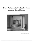
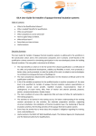
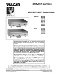
BASIC CABINET CONSTRUCTION
Fig. 1
F45509 (0813)
Page 4 of 23
INSTALLATION INSTRUCTIONS DEHUMIDIFYING PROOFING CABINET - GENERAL
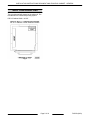
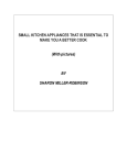
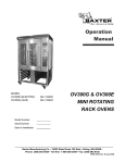
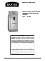
WALL CONFIGURATIONS
The right side wall will always be the solid wall. The
left side wall will contain the proofing system.
DPC1S Cabinet Witdh = 42.00"
Fig. 2
Page 5 of 23
F45509 (0813)
INSTALLATION INSTRUCTIONS DEHUMIDIFYING PROOFING CABINET - PREASSEMBLED CABINETS
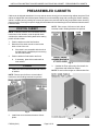
PREASSEMBLED CABINETS
Cabinet can be shipped assembled. You may want to remove door(s) prior to maneuvering cabinet into place. Each
cabinet is shipped with the individual parts needed for on site assembly along with a packing list. Before installing
cabinet, compare parts to packing list to ensure all parts were received. Wait as long as possible before removing
plastic protective covering from panels. Apply silicone between floor and wall angle or floor and base channel seams.
Leave no voids.
NOTE: Place a spot of silicone on back side of
brackets to aid in holding brackets into position.
POSITION CABINET
NOTE: If cabinet rear drain is not accessible from the
back when in final location, route the proofer drain
outside of the cabinet to the facility drain before setting
proofer in final location.
1.
Position cabinet near the final location.
2.
Determine if the drain must be routed out the
back or front of the unit.
A.
3.
If the drain is not accessible with the unit in
the final location, install drain prior to moving
unit into final location.
Position cabinet in final location and level.
A.
If necessary, place shims under walls to
level cabinet.
Fig. 4
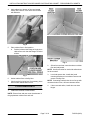
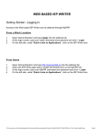
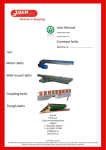
FLOOR
1.
3.
Install rear corner brackets at both rear corners
of cabinet.
(Cabinet No Floor option only) Check walls for
squareness and Install floor angles.
NOTE: Do not use floor angles on cabinets with floor.
NOTE: Place a spot of silicone on back side of
brackets to aid in holding brackets into position.
Fig. 3
2.
Install front corner brackets at bottom of door
jambs.
F45509 (0813)
Fig. 5
Page 6 of 23
INSTALLATION INSTRUCTIONS DEHUMIDIFYING PROOFING CABINET - PREASSEMBLED CABINETS
4.
Apply adhesive to bottom of floor and spread
evenly with a trowel. Cover entire floor surface
with adhesive.
Fig. 6
5.
Place cabinet floor in final position.
A.
Position left hand side flange of single piece
cabinet floor such that side flange is behind
air duct.
Fig. 9
2.
Silicon front and rear corner brackets to cabinet
floor and wall panels.
NOTE: One floor bracket for each side wall and one
for the rear wall.
3.
Fig. 7
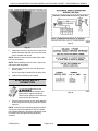
6.
Anchor cabinet floor to facility floor.
7.
Check proofer for being level. If necessary, place
shims under cabinet walls to level.
1.
NOTE: If mounting bracket holes do not line up with
clearance holes in floor, drill new clearance holes.
4.
FLOOR BRACKETS
Level and square door. Install door jamb
mounting brackets to front cabinet corners and
secure to facility floor.
If door removed earlier, install door onto door
hinges.
Install floor brackets to cabinet walls.
NOTE: Ensure front and rear corner brackets are in
the gap between cabinet floor and wall.
Page 7 of 23
F45509 (0813)
INSTALLATION INSTRUCTIONS DEHUMIDIFYING PROOFING CABINET - PREASSEMBLED CABINETS
Fig. 11
Fig. 10
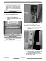
5.
Install outer floor trim, remove film covering from
double sided tape and seal trim to wall. Use roller
tool to complete seal to wall.
NOTE: Remove outer protective plastic after outer
floor trim is installed.
NOTE: Before installing outer floor trim, clean outer
wall surface with de-greaser.
6.
Silicone both front corner floor trim at top and
bottom seams.
7.
Secure front edge of cabinet floor to facility floor.
8.
Install air duct assembly onto cabinet.
ELECTRICAL SUPPLY
CONNECTION
Disconnect the
electrical power to the machine and
follow lockout / tagout procedures.
There may be multiple circuits. Be sure
all circuits are disconnected.
1.
Connect electrical supply per the wiring diagram
on the component box cover or back side of lower
front trim.
NOTE: If 208-240 volt electrical supply does not have
a neutral, a step-down transformer can be installed
(see following diagram). Step down transformer must
be installed in a leak tight housing supplied by
customer.
F45509 (0813)
Page 8 of 23
Fig. 12
INSTALLATION INSTRUCTIONS DEHUMIDIFYING PROOFING CABINET - PREASSEMBLED CABINETS
Fig. 13
FINAL CHECKS
1.
Remove all remaining protective plastic.
2.
Install plug buttons in unused holes i.e. wall and
ceiling panels.
3.
Ensure all holes with wiring / tubing thru wall &
ceiling panels are filled with silicone.
4.
Test for proper operation.
NOTE: The fans of each proofing system will run
continuously for 20 minutes after power has been shut
off at the controller.
5.
Calibrate cabinet for temperature and humidity
following instructions supplied. Dunkin' Donuts
Calibration or Standard Calibration
6.
Complete Installation Checklist and distribute
copies per instructions on checklist.
Page 9 of 23
F45509 (0813)
INSTALLATION INSTRUCTIONS DEHUMIDIFYING PROOFING CABINET - UNASSEMBLED CABINETS
UNASSEMBLED CABINETS
WALL PANEL
C.
Secure rear ceiling panel to side walls with
cam locks.
Refer to WALL CONFIGURATIONS section for
sequence of wall panel assembly. As walls are added,
ensure panel seals are on opposite sides.
D.
When placing front ceiling panel lock ceiling
panels together and then lock to side walls.
1.
Start with left rear corner at final position on
facilities floor.
FLOOR
1.
NOTE: Both rear corner panels should be positioned
with the cam locks at the top.
NOTE: Turn top cam CW and bottom cam CCW to
lock.
2.
Attach adjacent rear wall panel and left wall panel
to left rear corner and lock in place.
3.
Follow WALL CONFIGURATIONS to assemble
remaining panels.
Install rear corner brackets at both rear corners
of cabinet.
NOTE: Place a spot of silicone on back side of
brackets to aid in holding brackets into position.
Fig. 15
2.
Install front corner brackets at bottom of door
jambs.
NOTE: Place a spot of silicone on back side of
brackets to aid in holding brackets into position.
Fig. 14
CEILING PANELS
1.
Install ceiling panels.
NOTE: All cam locks on ceiling panels turn CW except
cam locks on front corner panels.
A.
Start with rear ceiling panel with the square
vent hole in it.
B.
Position rear ceiling such that vent hole is in
the right rear corner of the unit and align
edges of ceiling panel with rear wall and lock
into place.
F45509 (0813)
Page 10 of 23
Fig. 16
INSTALLATION INSTRUCTIONS DEHUMIDIFYING PROOFING CABINET - UNASSEMBLED CABINETS
3.
(Cabinet No Floor option only) Check walls for
squareness and Install floor angels.
NOTE: Do not use floor angles on cabinets with floor.
Fig. 19
NOTE: Floor brackets may need to be removed to
position the floor in place.
6.
Anchor cabinet floor to facility floor.
7.
Check cabinet for being level. If necessary, place
shims under cabinet walls to level.
8.
Install door jamb mounting brackets to front
cabinet corners and secure to facility floor.
NOTE: If mounting bracket holes do not line up with
clearance holes in floor, drill new clearance holes.
Fig. 17
4.
Apply adhesive to bottom of floor and spread
evenly with a trowel. Cover entire floor surface
with adhesive
Fig. 20
FLOOR BRACKETS
1.
Fig. 18
5.
NOTE: Ensure front and rear corner brackets are in
the gap between cabinet floor and wall.
Place cabinet floor in final position.
A.
Install floor brackets to cabinet walls.
Position cabinet floor such that side flange
is behind air duct.
NOTE: Only peel back protective plastic where floor
brackets are installed.
Page 11 of 23
F45509 (0813)
INSTALLATION INSTRUCTIONS DEHUMIDIFYING PROOFING CABINET - UNASSEMBLED CABINETS
A.
Route sensor through ceiling panel. Plug will
not fit through ceiling hole.
B.
Install sensor bracket onto ceiling.
Fig. 21
2.
Silicon front and rear corner brackets to cabinet
floor and wall panels.
3.
Level and square door(s).
4.
Install outer floor trim, remove film covering from
double sided tape and seal trim to wall. Use roller
tool to complete seal to wall.
Fig. 23
C.
Install sensor into clamp on sensor bracket.
NOTE: Do not remove the white protective covering
from humidity/temperature sensor.
NOTE: Only peel back protective plastic where outer
floor trim is installed.
NOTE: Ceiling has pre-drilled holes for mounting
sensor bracket.
NOTE: Before installing outer floor trim, clean outer
wall surface with de-greaser.
3.
5.
Silicone both front corner floor trim at top and
bottom seams.
6.
Secure front edge of cabinet to facility floor.
Position sensor 1/4" from end of bracket.
Fig. 24
4.
Install air duct assembly.
NOTE: Refer to WALL CONFIGURATIONS section
for air duct assembly location.
A.
Remove air intake cover and intermediate
panel from air duct assembly.
B.
Install air duct bolts loose into nut serts in
ceiling panel.
C.
Hang air duct assembly onto bolts using key
holes in air duct assembly.
D.
Secure air duct assembly to wall panel (4
places) and tighten ceiling bolts.
Fig. 22
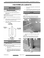
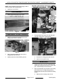
AIR DUCT ASSEMBLY
1.
Install plug buttons into unused holes that would
be behind air duct assembly.
2.
Install humidity/temperature sensor in top left
front corner inside cabinet.
F45509 (0813)
Page 12 of 23
INSTALLATION INSTRUCTIONS DEHUMIDIFYING PROOFING CABINET - UNASSEMBLED CABINETS
Fig. 25
E.
5.
Fig. 26
Install grommets into routing holes in air
duct assembly.
Route heater, fan, and high limit lead wires
through appropriate access hole in ceiling. There
will be a grommet around both the inner and outer
skin access holes.
NOTE: Insulation may need to be cleaned out of holes
so heater wires can be routed through.
6.
Install water line from solenoid to spray nozzle
using shallow radius bends.
Do not kink the water line.
NOTE: Fitting on spray nozzle is a self locking push
in type.
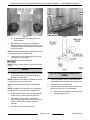
DRAIN
1.
Fig. 27
AIR INTAKE & INTERMEDIATE
PANEL
Install drain tube from outside of cabinet thru hole
in rear wall or hole in front wall depending on
location of facilities drain.
NOTE: Insulation may need to be cleaned out of hole
so drain tube can be routed through.
1.
Install intermediate panel to air duct assembly.
Intermediate panel fits inside air duct assembly.
NOTE: T drain assembly fittings are hand tighten
only.
2.
Install bumper to air intake cover.
3.
Install air intake cover onto air duct assembly. Air
intake cover fits over air duct assembly.
NOTE: Straight run of drain tube from air gap drain
should have a 1/4" slope per foot to cabinet wall.
2.
Install capped 4" drain tube into T drain assembly
coupler that is not being used for drain line.
3.
Cut tubing to proper length. Length will be
determined by location of proofer in proximity to
a wall or drain and the quantity of air ducts
installed.
4.
Silicone drain tube at wall of cabinet.
Page 13 of 23
A.
Secure cover in upper left corner of air duct
assembly with a screw.
F45509 (0813)
INSTALLATION INSTRUCTIONS DEHUMIDIFYING PROOFING CABINET - UNASSEMBLED CABINETS
Fig. 30
BUMPERS
1.
Remove the necessary protective plastic.
2.
Install left & right bumper(s) to walls.
3.
Install rear bumper to wall.
Fig. 28
4.
Install air flow panel.
A.
Install air flow panel mounting screws loose
into ceiling panel.
Fig. 29
B.
Mount the air flow panel onto mounting
screws.
NOTE: 90E flat bend fits against air intake cover
panel. Opposite end has angled bend to deflect air
upwards.
Fig. 31
F45509 (0813)
Page 14 of 23
INSTALLATION INSTRUCTIONS DEHUMIDIFYING PROOFING CABINET - UNASSEMBLED CABINETS
4.
Install bumpers onto bumper mounting bracket
for right front corner.
A.
Install bumper mounting bracket to right
front corner of cabinet.
Fig. 32
INTERIOR DIFFUSER DUCT
1.
Place duct in right rear corner and secure to
ceiling (2 places) and to rear corner (8 places)
using the provided drill tip screws.
Fig. 33
Fig. 34
Page 15 of 23
F45509 (0813)
INSTALLATION INSTRUCTIONS DEHUMIDIFYING PROOFING CABINET - UNASSEMBLED CABINETS
2.
At time of start-up check the operation of the fan
and vent by setting humidity to 70%. Once
humidity reaches 70% change setting to 60%.
Fan will turn on and vent will open. Change
humidity to 70%, fan will turn off and vent will
close.
DOOR HANDLE
1.
Remove the necessary protective plastic.
2.
Install door handle and door bumper.
A.
Install mounting screws through bumper.
B.
Attach bumper to inside of door.
C.
Using same screws, attach handle to front
of door.
Fig. 36
2.
Install male half of hinges to door.
NOTE: Do not stand door up on the door seal.
A.
Remove existing screws from hinge side of
door and install hinge. Position post
downward.
Fig. 35
DOOR HINGES
1.
Install female half of hinges to cabinet. Ensure
bushing is installed in hinge.
NOTE: Torque hinge bolts to 90 in. lbs. or 71/2 ft. lbs.
Fig. 37
B.
3.
F45509 (0813)
Page 16 of 23
Remove screws from other side of door and
replace with plug buttons if necessary.
Install plug buttons onto hinge screws on both
door assembly and cabinet.
INSTALLATION INSTRUCTIONS DEHUMIDIFYING PROOFING CABINET - UNASSEMBLED CABINETS
NOTE: Before installing plug buttons apply a dab of
silicone on back side of plug buttons.
4.
Install door onto cabinet.
DOOR MAGNET
1.
Install magnet assembly to top of door.
Fig. 38
COMPONENT & JUNCTION BOX
1.
Fig. 40
4.
Install the component box assembly to top of
ceiling panel at front of cabinet.
Connect plugs from heater, fan, high limit and
solenoid to plugs from component box.
Fig. 39
2.
3.
Verify grommets installed into wire holes in
ceiling panel above air duct.
Fig. 41
Install junction box with self drilling screws.
A.
Seal holes in ceiling panels with silicone.
B.
Install cover on junction box.
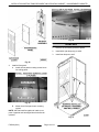
REAR VENT
1.
Confirm rear ceiling has been installed with the
square vent opening in the right rear corner of the
unit – furthest away from the heat duct.
2.
Place vent assembly over the hole in rear ceiling
panel and secure to ceiling through the four
mounting brackets using the provided self drilling
screws.
A.
Page 17 of 23
Make sure fan is facing center of unit.
F45509 (0813)
INSTALLATION INSTRUCTIONS DEHUMIDIFYING PROOFING CABINET - UNASSEMBLED CABINETS
Fig. 42
Fig. 44
B.
Inside the control box, locate the Molex
housing on the power supply board.
1)
Connect pin on wire #20 to location #9
in the molex.
Fig. 43
3.
Connect wiring to control box:
A.
Remove one knockout and insert conduit
from vent assembly into back of control box.
Fig. 45
2)
Connect pin on wire #17 to location #4.
Fig. 46
F45509 (0813)
Page 18 of 23
INSTALLATION INSTRUCTIONS DEHUMIDIFYING PROOFING CABINET - UNASSEMBLED CABINETS
3)
Locate the 5 section terminal block and
connect the white wire to the position
labeled neutral.
Fig. 49
A.
Seal water line hole in ceiling panel with
silicone.
Fig. 47
WATER SUPPLY LINE
CONNECTION
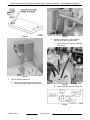
1.
Connect water line to solenoid.
Fig. 50
TRIM PANELS
1.
Install both forward side trim panels.
Fig. 48
2.
Connect water line from air duct assembly to
output of solenoid using elbow and tube
assembly shown in photo below.
Fig. 51
Page 19 of 23
F45509 (0813)
INSTALLATION INSTRUCTIONS DEHUMIDIFYING PROOFING CABINET - UNASSEMBLED CABINETS
2.
Install lower front trim and secure with top screws
to both side trims.
NOTE: Lower front trim installed during controller to
component box connection procedure.
NOTE: Upper front trim installed during electrical
supply connection procedure.
NOTE: Upper, lower and side trim panels can be
assembled together before installing onto cabinet.
CONTROLLER TO COMPONENT
BOX CONNECTION
Fig. 53
Install wiring that connects controller to component
box.
6.
NOTE: The lead wires are routed through the 90
degree conduit from factory. One wire is marked with
red. Connect this wire to board connections marked
with red.
Use care not to damage the control
harness during lower front trim installation.
1.
Install conduit clamp loose on top of the door.
7.
2.
Insert longer side of the 90 degree conduit under
conduit clamp on top of door.
Carefully feed control wires and end of conduit
through hole in lower forward trim. Install
grommet into lower front trim.
3.
Finger tighten conduit clamp screws on top of
door.
8.
4.
Insert control cables through top of door and into
control compartment. Gently pull any slack
excess control cable from the top of the unit
through and into the control compartment.
Install lower front trim and secure to both side trim
pieces. Center short leg of conduit in bushing in
lower front trim and open and close loading door
to assure the conduit does not bind. Fully tighten
conduit clamp on top of door.
Fig. 52
5.
Fig. 54
Install strain relief bushings at top of door around
each control cable. Seal with clear silicone to
obtain water tight seal around cables.
F45509 (0813)
Slip grommet for front trim over lead wires and
short leg of conduit..
9.
Page 20 of 23
Apply clear silicon caulking around the perimeter
of the control opening in the control door.
INSTALLATION INSTRUCTIONS DEHUMIDIFYING PROOFING CABINET - UNASSEMBLED CABINETS
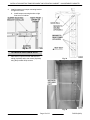
12. Adjust cables so that 5 inches extend through the
mounting plate. Install strain relief bushings
around cables and press into holes in mounting
plate. Seal bushings and cables with clear
silicone caulk.
13. Connect lead wires to controller.
Fig. 55
10. Feed the control cables through the access holes
in the mounting plate leaving sufficient cable in
the control compartment such that the control
cables loop below the access holes in the
mounting plate.
Fig. 58
14. Connect lead wires to power board in component
box
NOTE: The cable with the red tape should be plugged
into the PCB socket with the same color tape on it.
Fig. 56
11. Attach mounting plate to door face with #10-32,
Stainless Truss head screws (4 places).
Fig. 59
15. Mount Standoff cover to mounting plate using
#10-32 Stainless Truss head screws supplied (4
places).
Fig. 57
Page 21 of 23
F45509 (0813)
INSTALLATION INSTRUCTIONS DEHUMIDIFYING PROOFING CABINET - UNASSEMBLED CABINETS
Fig. 60
NOTE: Louvers should be located at the sides and
bottom of the cover.
Fig. 62
Fig. 61
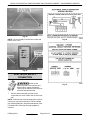
ELECTRICAL SUPPLY
CONNECTION
Disconnect the
electrical power to the machine and
follow lockout / tagout procedures.
There may be multiple circuits. Be sure
all circuits are disconnected.
1.
Connect electrical supply per label on the
component box cover or back side of lower front
trim.
NOTE: If 208-240 volt electrical supply does not have
a neutral, a step-down transformer can be installed
(see following diagram). Step down transformer must
be installed into a leak tight housing supplied by
customer
F45509 (0813)
Page 22 of 23
Fig. 63
INSTALLATION INSTRUCTIONS DEHUMIDIFYING PROOFING CABINET - UNASSEMBLED CABINETS
Fig. 64
FINAL CHECKS
1.
Remove all remaining protective plastic.
2.
Install plug buttons in unused holes i.e. wall and
ceiling panels.
3.
Ensure all holes with wiring / tubing thru wall &
ceiling panels are filled with silicone.
4.
Test for proper operation.
NOTE: The fans of each proofing system will run
continuously for 20 minutes after power has been shut
off at the controller.
5.
Calibrate cabinet for temperature and humidity
following instructions supplied. Dunkin Donuts
Calibration or Standard Proofer Calibration
6.
Complete Installation Checklist and distribute
copies per instructions on checklist.
Page 23 of 23
F45509 (0813)