1
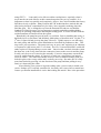
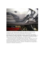
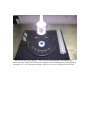
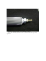
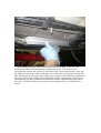
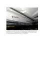
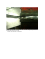
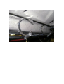
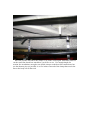
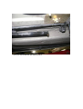
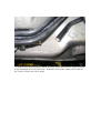
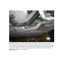
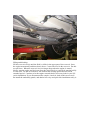
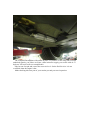
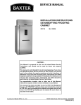
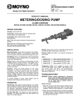
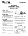
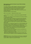
E-Z Inline Power Steering Cooler Install for Porsche 9x6 and 9x7
Do you find you are having consistent problems with power-steering fluid boil-over
and pump cavitation? You may not even be aware that its happening until you see the
drip make it to the floor, or have a steering groan and, at times, high steering effort ?
Maybe you seem to have to add steering fluid often despite evidence of a leak. The case
webbing has a tendency to catch a fairly large volume of fluid, which often doesn’t
make its appearance until enough has accumulated and aggressive driving puts it over the
edge, literally.
Naturally, the high revs associated with track events and autocross result in very high
P/S pump speeds, fluid velocity, and fluid pressure. Also, consider that there is an
increased demand for power steering assist, as well as more feedback from the road or
track. Most importantly, is the increase in both operational and ambient temperature and
the resultant fluid expansion, hence the expansion tank, and overflow tube –which is
often wet, even under normal use. However, it is usually track use that pushes the system
to its limit: the fluid boils over, the level drops thus the pump cavitates, and the high
pump speeds whip the aerated fluid into an expanding froth. The mid-engine cars seem to
be more prone to it, possibly due to the fact that the steering fluid lines are positioned
more closely to ambient heat sources. Some say that “sawing at the wheel “ can
exacerbate the problem, and I don’t doubt it. However, it can still occur even with the
smoothest of steering input. Not surprisingly, the GT3(and 911 Turbo) doesn’t seem to
have this problem -it has a much larger drive pulley, an appropriately valved P/S rack, a
robust pump, and an aluminum reservoir.
Excessive bump steer can also contribute and may damage the rack and/ or pump.
There is a check valve/flow control orifice installed in the end of the pressure line where
it enters the rack. I have seen this device damaged and even turned sideways in the bore
from pressure spikes resulting from wheel impact-an extreme form of bump steer, right
!! When this happens, the pump screams without any steering, and there is no power
steering assist at all. On the other hand, low fluid level usually manifests itself as
groaning as the wheel is turned away from center, and there is still some assist.
Obviously, a power steering cooler will not remedy the former condition. A cooler will
help abate the boil over problem when installed within a system that is in good working
order. It’s not a cure, but a prevention. Combine a cooler with an underdrive pulley and
the use of an alternative P/S fluid for optimal results.
Due to shrinking budget, I first tried the cheapest of solutions-a catch tank. Sound
principle, but what I found was that the bulk of the overflowing fluid was not making it to
the overflow hose, although it was “wet”. Most of the fluid had breached the o-ring that
seals the connection between the upper and lower reservoir and the reservoir cap itself.
The o-rings were new at the time I installed the catch tank. After dutifully cleaning the
affected area, I refilled the reservoir, and bled the system of ingested air. Bleeding is
easy and I’ll cover it at the end of the install procedure.
By the way, the Pentosin steering fluid used by Porsche (Goo 2000 for VW folks) is
aggressive to many types of rubber and plastic, as well as paint and other coatings. The
factory service manual advises the immediate cleanup of any spilled P/S fluid, with soap
and water. The current factory fluid is Pentosin CHF 202. It is fully synthetic and can be
mixed and used in place of the Pentosin CHF 11s. It’s not compatible with systems
using CHF 7.1. I can testify to its effect on rubber cooling hoses, especially when it
seeps into the cut ends of hoses at their connection points-can you say swollen? It is
important to clean it up quickly and completely. Also,we have also found that the factory
fluid does slowly evaporate. Many Porsche and VW technicians have noticed this and
after having checked comprehensively for leaks, have stopped wondering where the
fluid has gone. We’ve changed away from the Pentosin line and now use Redline
Synthetic P/S fluid because it is less aggressive to plastic and rubber and has higher
viscosity at operating temperature and a higher boiling point. It is also miscible with the
residual amounts of Pentosin left in the system.
Remarkably, the pump has proved itself very resilient. Prior to installing the cooler, it
had boiled over several times, and definitely made plenty of horrible noise. By the 4th or
5th time, I figured it had given up the ghost. However, I gladly report we are still using
the same pump, and after the cooler installation we have had no problems to date. This
may not be your experience. The pump isn’t easy to get to, and replacing it on a Boxster
or Cayman isn’t the easiest job I’ve ever done. Even so, it’s not terrible and I would still
rather replace a P/S pump than get a root canal. One area that can leak when the system
has been hot is the o-ring that seals the connection between the reservoir and the pump.
It really can’t be seen w/o removing the assembly. Excessive temperature can melt the
reservoir and deform the plastic, so I guess it is really not o-ring failure, but instead,
reservoir failure. The return line into the reservoir is not a common leakage point, it is
locked in place with a swage collar and is sealed by an o-ring. Do make sure it is fully
seated and locked by pressing it in the direction of the pump and then pulling it away
firmly w/o depressing the collar.
After ensuring your system is in good working order, you are ready to install your
cooler. Perhaps you’ve already considered it , but really aren’t sure where to mount one.
I assure you that the installation is easier than reading this article! Here is the procedure:
Remove the center underbody panels and the one on the driver’s side. Here is the
installation location. Driver’s side, just rearward of the foot-well area.
Install the cooler inline with the return line in this area. It is the lower line with the
largest diameter. The cluster of three lines are vacuum, fuel and fuel vapor lines-don’t cut
these! The P/S lines are made of aluminum, coated with plastic. They cut very easily
using a commercially available tubing cutter. I would not recommend using an abrasive
cut-off wheel to cut the lines. The tubing cutter gives the best results.
Undo the clamps that are securing the P/S lines to the body. Drain the system of P/S
fluid by disconnecting the coupler that is located under the driver’s side panel. If you
don’t know how to disconnect and re-connect the coupler, consult a service manual or
simply drain the fluid when you cut the return line- be mindful of the emerging fluid, it
may spurt a bit. But don’t cut the line yet…
Here are the necessary supplies. The cooler, the fitting adapters, the fittings, pipe
thread tap, hose clamps for the lines, hose clamps for the mounting, power steering fluid,
and approx 16” of 3/8 fuel/gas rated hose. The two rivets you will need are not shown.
The adapters and fitting installed on the cooler using thread tape…
Update: I have found Pipe Sealant w/Teflon to seal better than Teflon Tape in this
application.
The installation location. Notice that the line isn’t cut yet. Don’t cut it yet. The
pressure line, which will remain intact, is behind the cooler. Test fit the cooler,
encourage the pressure line upward, it will reside in the cavity formed by the cooler and
the frame rail. Orient the cooler so that the t-slot on the cooler is facing the pressure line.
This will give the pressure line some wiggle room so that it is not captured or smashed by
the cooler. The T-slot could be used for mounting, but the clamp system is much easier
While holding it in place, mark the position of the clamps, equidistant from the ends of
the cooler. Eyeball it unless you just like using measuring tools. It’s called E-Z for a
reason!
Mark the area for the holes for the clamp rivets. A bit more than halfway up from the
bottom edge of the frame rail works well. Drill a pilot hole, drill the diameter hole and
test fit your rivets. I recommend rivets over sheet metal screws. If you do use screws,
use nut-serts and thread locker. But really, the rivets are E-Z!
Drill a pilot hole in the mounting clamp is the area of the clamp just beyond where the
threads on the band taper to a point.
Drill the same hole to the rivet diameter.
Install the clamps using the rivets. Orient the clamp so you can tighten it from below.
Place the pressure line above the clamps. Test fit the cooler again. Determine where to
cut the return line based how much hose you’d like to use. Use enough length for
tension free installation, enough to use double clamps on the hose/line connections, but
use the shortest piece(s) possible. 4 or five inches rearward of the clamp that secures the
line to the body will do the trick.
Now you can cut the line and drain the fluid.
Cut the line for the forward hose below the elbow and so that it can be again positioned
in the clamp that secures it to the body. Install the cooler in the clamps, test fit and cut
the 2 pieces of hose you will be using.
Install the hose, use a double clamp on the connection for the hose/line as it has no hose
barb to lock thee hose. The fitting has a barb on it, but you may use 2 clamps there as
well. I did use double clamps on all connections on the last one I did. Position the return
line in the body clamps. Here is a picture of the forward hose/line installed in the factory
clamp. The pressure line is shown not installed in the clamp for reasons of clarity of
illustration.. Put that one in there, too
Clean and E-Z!
Filling and bleeding:
Fill the reservoir slowly until the fluid is visible in the upper part of the reservoir. Start
the engine momentarily and then shut it down. Correct the level in the reservoir. Do this
several times. When the reservoir level no longer drops when the engine is started
briefly, start the engine and let it run. Steer the wheel slowly to each lock, pausing briefly
at each lock. Do this several times. Do not hold the steering against the lock for an
extended period. Continue to let the engine run and check/correct any leaks in your P/S
cooler installation. If you disconnected the coupler, check for leaks in this area as well.
Re-install the underbody panels, and admire how easy and quick this installation really is.
The completed installation with panels in place. If you have or are using full coverage
underbody panels, you’ll have to create a duct in them to supply your cooler with air. A
hole saw will work well to accomplish this.
Take her out for spin and correct the reservoir level. Set the fluid level so it is not
overfilled when the engine is hot.
Make checking this area part of your routine pre-and post race inspection.