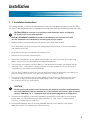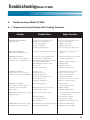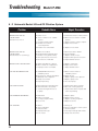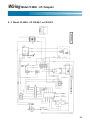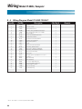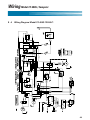
1
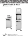
Operations & Service Manual
CF-400G
Giles Enterprises, Inc.
FOODSERVICE EQUIPMENT
An ISO9001 Registered Company
2750 Gunter Park Drive West • Montgomery, AL 36109 USA
Fax: (334) 272-3561 • Internet: www.gilesent.com
Service Hotline (Toll Free): 1-800-554-4537 (USA & Canada Only)
Form No. 60201 (Revised 01/04/07)
Safety
FOR YOUR SAFETY
!
DO NOT store or use gasoline or use gasoline or other flammable vapors
and liquids in the vicinity of this or any other appliance!
!
WARNING
Improper installation, adjustment, alteration, service or maintenance can
cause property damage, injury or death. Read the installation, operating,
and maintenance instructions thoroughly before installing or servicing this
equipment.
POST IN A PROMINENT LOCATION instructions to be followed in the event the user
smells gas. This information shall be obtained by consulting the local gas supplier.
Table of Contents
Model: CF-400G
I
Introduction
1
Installation
1-1
Installation Instructions . . . . . . . . . . . . . . . . . . . . . . . . . . . . . . . . . . . . . . . . . . . . . . . . . . . . . . . . . . . . . . . . . . . . . . . . . . . . . . . . . . . . . . . . . . . . . . . . . . . . . . . 3
1-2
Removal of Fryer From Crate
1-3
Ventilation of Fryer
1-4
Electrical Requirements . . . . . . . . . . . . . . . . . . . . . . . . . . . . . . . . . . . . . . . . . . . . . . . . . . . . . . . . . . . . . . . . . . . . . . . . . . . . . . . . . . . . . . . . . . . . . . . . . . . . . . 7
2
Operating Instructions
3
Fryer Components and Their Functions
3-1
Control Panel
3-2
Lower Cabinet Area . . . . . . . . . . . . . . . . . . . . . . . . . . . . . . . . . . . . . . . . . . . . . . . . . . . . . . . . . . . . . . . . . . . . . . . . . . . . . . . . . . . . . . . . . . . . . . . . . . . . . . . . . . . . 12
3-3
Cooking Vessel . . . . . . . . . . . . . . . . . . . . . . . . . . . . . . . . . . . . . . . . . . . . . . . . . . . . . . . . . . . . . . . . . . . . . . . . . . . . . . . . . . . . . . . . . . . . . . . . . . . . . . . . . . . . . . . . . . . 14
3-4
Cooking Computer Features
3-5
Cooking Computer Function Keys . . . . . . . . . . . . . . . . . . . . . . . . . . . . . . . . . . . . . . . . . . . . . . . . . . . . . . . . . . . . . . . . . . . . . . . . . . . . . . . . . . . . . . . . 17
3-6
Cooking Computer Programming
4
Testing the Fryer
4-1
Proper Control Settings for Check-Out
4-2
Operational Check of Burner System . . . . . . . . . . . . . . . . . . . . . . . . . . . . . . . . . . . . . . . . . . . . . . . . . . . . . . . . . . . . . . . . . . . . . . . . . . . . . . . . . . . 20
4-3
Operational Check-Out of the Filter Pump . . . . . . . . . . . . . . . . . . . . . . . . . . . . . . . . . . . . . . . . . . . . . . . . . . . . . . . . . . . . . . . . . . . . . . . . . . . . 21
5
Preparing the Fryer for Operation
5-1
Fryer Boil-Out Procedure . . . . . . . . . . . . . . . . . . . . . . . . . . . . . . . . . . . . . . . . . . . . . . . . . . . . . . . . . . . . . . . . . . . . . . . . . . . . . . . . . . . . . . . . . . . . . . . . . . . . . 22
5-2
Cleaning of Filter Pan / Replacement of Filter Pan . . . . . . . . . . . . . . . . . . . . . . . . . . . . . . . . . . . . . . . . . . . . . . . . . . . . . . . . . . . . . . . . . 27
5-5
Operating Fryer Controls for Cooking . . . . . . . . . . . . . . . . . . . . . . . . . . . . . . . . . . . . . . . . . . . . . . . . . . . . . . . . . . . . . . . . . . . . . . . . . . . . . . . . . . . 29
5-6
Filtering the Fryer . . . . . . . . . . . . . . . . . . . . . . . . . . . . . . . . . . . . . . . . . . . . . . . . . . . . . . . . . . . . . . . . . . . . . . . . . . . . . . . . . . . . . . . . . . . . . . . . . . . . . . . . . . . . . . . 30
..................................................................................................................
2
..............................................................................................
7
.............................................................................................................
7
.................................................................................................
.....................................................................................................................
...............................................................................................
........................................................................................
.................................................................................
8
11
16
18
20
Table of Contents
Model: CF-400G
6
Troubleshooting
6-1
Temperature Control System . . . . . . . . . . . . . . . . . . . . . . . . . . . . . . . . . . . . . . . . . . . . . . . . . . . . . . . . . . . . . . . . . . . . . . . . . . . . . . . . . . . . . . . . . . . . . . . 31
6-2
Automatic Basket Lift and Oil Filtration System
7
Parts
7-1
Front Control Panel . . . . . . . . . . . . . . . . . . . . . . . . . . . . . . . . . . . . . . . . . . . . . . . . . . . . . . . . . . . . . . . . . . . . . . . . . . . . . . . . . . . . . . . . . . . . . . . . . . . . . . . . . . . . . 34
7-2
Rear View of Lower Cabinet . . . . . . . . . . . . . . . . . . . . . . . . . . . . . . . . . . . . . . . . . . . . . . . . . . . . . . . . . . . . . . . . . . . . . . . . . . . . . . . . . . . . . . . . . . . . . . . . 35
7-3
Rear View of Header Section . . . . . . . . . . . . . . . . . . . . . . . . . . . . . . . . . . . . . . . . . . . . . . . . . . . . . . . . . . . . . . . . . . . . . . . . . . . . . . . . . . . . . . . . . . . . . . . 36
7-5
Filter Pan Assembly . . . . . . . . . . . . . . . . . . . . . . . . . . . . . . . . . . . . . . . . . . . . . . . . . . . . . . . . . . . . . . . . . . . . . . . . . . . . . . . . . . . . . . . . . . . . . . . . . . . . . . . . . . . . 37
8
Wiring Diagrams
8-1
Model CF-400G 208/240/60/1 . . . . . . . . . . . . . . . . . . . . . . . . . . . . . . . . . . . . . . . . . . . . . . . . . . . . . . . . . . . . . . . . . . . . . . . . . . . . . . . . . . . . . . . . . . . . . . 38
8-2
Model CF-400G 208/240/60/1 . . . . . . . . . . . . . . . . . . . . . . . . . . . . . . . . . . . . . . . . . . . . . . . . . . . . . . . . . . . . . . . . . . . . . . . . . . . . . . . . . . . . . . . . . . . . . . 40
8-3
Model CF-400G 220/50/1 or 240/50/2
8-4
Model CF-400G 120/60/1
....................................................................
32
..................................................................................
42
....................................................................................................
44
Introduction
Congratulations on the purchase of your new Giles Gas Fryer. The Giles Model
CF-400G fryer is equipped with a high quality Cooking Computer. This new “User friendly” easily programmable Cooking Computer incorporates extensive design detail by its manufacture WATLOW, and extensive cooking application by the “Giles” engineering team. The new cooking computer along with the Giles
fryer is truly a “world class” product.
To help protect your investment in this state-of-the-art cooking equipment, we recommend you
take a few moments to familiarize yourself with the installation, cleaning and maintenance procedures
contained in this manual. Adherence to these recommended procedures minimizes the potential for
costly “Down-Time” and equipment repairs.
Parts Ordering and Service Information
If you require repair or assistance, please contact your local independent distributor. If you require further
assistance please contact our corporate office in Montgomery, Alabama at 1-800-554-4537.
Please have the following information available when calling for assistance. It may be helpful to record this
information in the blanks provided below for a quick reference.
1.
Model Number:
2.
Serial Number:
3.
Gas Type (L.P or Nat.):
4.
Voltage:
5.
Nature of Problem:
2
Installation
1 - 1 Installation Instructions
This section provides a summary of the procedures necessary for proper installation of your new Giles
Gas Fryer. To prevent personal injury or equipment damage, please ensure the following steps are taken:
!
1.
For Your Safety do not store or use gasoline or other flammable vapors and liquids in
the vicinity of this or any other appliance!
POST IN A PROMINENT LOCATION instructions to be followed in the event the user smells
gas.This information can be obtained by consulting your local gas supplier.
2. Keep the appliance and surrounding area free and clear from combustible materials:
For CF-400G allow a minimum clearance from combustible oil construction of 4" (10.2cm) from bottom,
side and back of the Fryer.
3. Do not obstruct the flow of combustion and ventilation of air.
4. Please retain this manual for future reference.
5. Please note wiring diagrams for this appliance are located in the rear of the manual. Ensure the wiring
diagram which you consult corresponds to the model being operated.
6. The installation must conform with local codes or, in the absence of local codes, with National Fuel Gas
Code ANSI Z223.1 - 1988. When in Canada, installation must be in accordance with CN 1-B149.1 or .2 .
Installation must also conform with ANSI/NFPA 96.
7.
The Fryer and its individual shutoff valve must be disconnected from the gas piping system during any
pressure testing of that system at test pressure in excess of 1/4 psig (3.45 kPa).
8. The Fryer must be isolated from the gas supply piping system by closing its individual manual shutoff
valve during any pressure testing of the gas supply piping system at test pressures equal to or less
than 1/4 psig (3.45 kPa), (14" water column).
!
CAUTION
The flue gases of this appliance must be vented to the outside in accordance with National Fuel
Gas Code, ANSI Z223.1-1988 and terminate in a UL listed outside vent terminal. When in Canada
reference CANI-B149.1 or .2 “Installation Codes for Gas Burning Appliances and Equipment”.
9. Please ensure this appliance is electrically grounded in accordance with local codes, or in the absence
of local codes, with the National Electrical Code, ANSI/NFPA 70 - 1990. When in Canada reference
CSA C22-1 “Canadian Electrical Code Part 1”.
10. Please provide adequate room for servicing and proper operation of this appliance. Also, provide
adequate ventilation in the operating area where necessary.
3
Installation
11. Make sure the Gas Connector complies with Standard for Movable Gas Appliance, ANSI, 69-1987 and Addenda
Z21.69-1989 (in Canada CANI-6-10-88), and the quick disconnect device complies with the Standard for QuickDisconnect Devices for Use with Gas Fuel, ANSI Z21.41-1989, (in Canada CANI 6.9 M79). Adequate means
must be provided to limit the movement of the fryer. A ring which is located on the lower right hand side of the
fryers back is to be used for the attachment of a restraining devise.
12. Please provide for adequate air intake into combustion chamber.
13. Always consult with an electrician or other individual prior to installation.
14. Ensure voltage, amperage, and gas type (PROPANE OR NATURAL GAS ONLY) supplied to the unit
are as specified on the fryer’s rating plate.
IMPORTANT NOTE
The wrong Fuel Source can damage the Fryer Unit and void the warranty.
15. To avoid the splashing of hot liquid make sure this unit is in a secure position such as connected to a battery of
appliances or adequately tied and will not move or tip. Locking casters are supplied on this unit—use them!
17. This appliance is to be installed, used and maintained in accordance with the Standard for Ventilation
Control, and Fire Protection of Commercial Cooking Operations, NFPA 96-1994.
!
DO NOT Modify, Alter or Add Attachments to This Equipment!
The above steps will help to ensure safe and proper installation of your fryer. If you have any questions
concerning these procedures, contact your local Giles distributor or other qualified service person.
4
Gas Fryer Setup Instructions “All Units”
1. Check location elevation and verify unit is setup for proper elevation.
2. Fill the cooking vessel with water.
3. Turn off gas supply.
4. Turn off power.
5. Remove the back panel(s) upper and lower.
6. Remove the gas line (tube) from the orfice holder (bottom of the burner).
7. Remove the orfice holder by turning it counter clockwise. The altitude is stamped on the orfice. Verfiy
that the orfice size is for the correct altitude.
8. Put the orfice holder back in place.
9. Locate the pressure tap on the gas valve and take out the plug.
10. Connect a water column (manometer) to the gas valve. (Where you removed the plug from).
11. Turn the power on.
12. Turn on gas supply and read water column 10.5 inches LP or 3.5 inches natural.
13. Adjust gas pressure as required. By removing the cap on the valve covering the pressure
adjustment screw. (If pressure is correct, do not adjust).
14. Turn off gas supply.
15. Turn off the power.
16. Remove the water column from the gas valve.
17. Put the plug back in place.
18. Put the back panel(s) back on the unit.
19. Turn on the gas supply.
20. Turn on the power.
21. The unit is ready for operation.
22. Proceed with the boil out procedure.
* Check Vacuum Switch Operation With Procedure, 2nd Page*
5
Gas Fryer Setup Instructions “All Units”
1.
Using a non-combustible cover, place it over the vent stack covering half of the stack.
2. The unit burner should be shut off, after removing the cover, the unit will re-ignite.
3. Adjust the vacuum switch if the unit doesn’t shut off when covered.
4. Turning the adjusting screw clockwise
increases sensitivity.
5. If it takes more coverage to shut down the
unit, the switch is not sensitive enough,
if covering only 1/4 shuts the unit down,
it too sensitive.
6
Installation
1 - 2 Removal of Fryer from Crate
Your Giles Fryer may arrive enclosed by a wooden crate. If your unit arrived uncrated, go to Section 1-3.
The Fryer is secured to a wooden platform by means of high-tensile strength strapping.
1.
Carefully cut and remove the plastic shipping wrap and the strapping mentioned above.
2. Use pliers to loosen wire hooks which secure the wooden crate around the fryer. Remove the wooden crate.
3. Carefully remove the fryer from the shipping platform. Your new fryer is extremely heavy and great
care should be taken in lifting or moving the unit to prevent personal injury or equipment damage.
1 - 3 Ventilation of Fryer
Your new Giles Gas Fryer has been designed for operation beneath a traditional exhaust hood. We strongly recommend you consult a professional ventilation or heating and air conditioning
company for assistance in designing a hood for an exhaust system.
IMPORTANT NOTE
Guidelines for proper ventilation system requirements may differ. Always consult with local authorities to
ensure compliance.
1 - 4 Electrical Requirements
!
WARNING
Fryers must be adequately and properly grounded. Improper grounding may result in electrical
shock. Always refer to your local electrical code to ensure proper grounding of this or any other
electrical equipment. Always consult with an electrician or other qualified service person to ensure
breakers and wiring are of sufficient rating and gauge for the equipment being operated.
Giles Fryers are available from the factory wired for 120, 208 or 240 volts, and single phase only, 50/60HZ.
service and set for either Natural or LP Gas. Check the rating plate on the door of the fryer to determine
the correct power supply and fuel type.
7
Operating Instructions
2
Operating Instructions
For your safety, please observe the following precautions when operating your Giles Fryer:
1.
Ensure the fry kettle is positioned in a secure, safe location with the casters in the locked position.
A restraining device attachment ring is located on the lower right hand side of the Fryer.
2. Due to the high temperature of shortening in your fryer during cooking, it is extremely important the
user exercise caution in operating this equipment to avoid personal injury.
3. Never move a fryer that contains hot oil! To avoid hazards associated with moving a fryer with liquid in
the vessel, always allow adequate time for the liquid to cool.
4. If for any reason it becomes necessary to disconnect the fryer’s restraining device, ensure the
restraining device is reconnected and the Fryer is returned to its original installed position.
5. Make sure all electrical and gas specifications have been met and the unit is grounded (see wiring
diagram in Section 10).
6. In the event of power failure, DO NOT try to operate the unit.
Lighting and Shut-Down Instructions
1.
Open the Main Gas Valve, turn Power Switch on.
2. Set the Thermostat to the desired temperature. (Giles Gas Fryers are provided with an
automatic direct ignition system which eliminates the need for a pilot light).
3. In the event the burner does not ignite, a beeper will sound. Wait 5 minutes before attempting to
restart the Fryer.
4. To RESTART, switch the Fryer’s main Power Switch to the “OFF” position. Return the Main Power
Switch to the “ON” position and set the desired temperature.
5. To SHUT-DOWN the Fryer, turn the thermostat and the Fryer’s Main Power Switch to the “OFF”
position, then CLOSE the Gas Supply Valve.
8
Model CF-400G
9
Fryer Components and Their Functions
3
Fryer Components and Their Functions
The following section is designed to introduce you to the controls used in operating this equipment.
!
DO NOT attempt operation of this unit until you have located each control discussed and fully
understand their intended function. Failure to do so may result in improper operation resulting in
equipment damage or personal injury to the operator.
Please review this section carefully before proceeding any further.
Refer to the accompanying photographs for the location of the components discussed.
Cooking Computer Control Panel Components and Their Functions
10
ITEM
DESCRIPTION
FUNCTION
1. Fig. 1
Power Switch
The Power Switch is a two-position switch.
Move the switch upward to the “ON” position
for operation.
2. Fig. 1
Selector Switch
The Selector Switch is a three-position switch which is
used to select either the cook, off or filter mode of
operation. The fryer’s Heat Exchanger will only operate
in the “COOK” position. The switch should be placed
in the “FILTER” position to filter the shortening which
will allow the pump to operate.
3. Fig. 1
Cooking computer
The Cooking Computer is used to select oil temperatures, cooking times and basket lift operations.
Programming of the cooking computer is covered later
in the manual.
Model CF-400G
3 - 1 Control Panel
Figure 1
2
3
8
1
9
10
ITEM
DESCRIPTION
FUNCTION
8. Fig. 1
Power Indicator Light
The Green Power Light is on whenever the fryer’s
Master Power Switch is in the “ON” position.
9. Fig. 1
Heat Indicator Light
The Orange Heat Indicator Light will be on when the
fryer’s Heat Exchanger is operating. When the selected
operating temperature is reached, the light will go off.
10. Fig 1
High-Limit Indicator
The High-Limit Indicator Light is illuminated as a result
of power being shut off to the fryer’s Heat Exchanger
by the built-in solid-state control circuit. If it comes on
during operation, refer to the trouble-shooting section
of this manual.
NEVER cook in a fryer with the High-Limit Light on!
11
Fryer Components and Their Functions
3 - 2 Lower Cabinet Area
ITEM
DESCRIPTION
FUNCTION
1. Fig. 2
Filter Pan Hold-Down
Bracket and Latches
The Hold-Down Bracket is contained in the filter pan
and serves to ensure the filter paper is held tightly
in place by means of the four locking latches. The
fryer’s filtering action will be reduced or eliminated if
these latches are not properly secured.
2. Fig. 2
T-Handle/Drain Valve
Turning this T-Handle counter-clockwise allows shortening to drain from the frying vessel into the filter pan.
Open the valve slowly to avoid burns from
splashing of hot oil. Always ensure the valve is closed
prior to adding shortening. Your fryer will not operate
if this Drain Valve is not completely closed. (i.e.,
clockwise)
3. Fig. 2
Drain Valve Pipe-Drain
This Pipe-Drain attaches to the Drain Valve and helps
to minimize splashing of hot oil when the fry-kettle is
filtered or drained. The Pipe-Drain must be removed
before sliding the filter pan out of the fryer. Always
use insulated gloves to remove this hand tightened
pipe.
4. Fig. 2
Quick Disconnect
Oil Discharge Wand
This Quick-Disconnect Fitting is used in conjunction
with the oil discharge wand to remove oil from the
fryer that is to be discharged.
5. Fig. 2
Diverter Valve
The Diverter Valve may be identified by its colored
lever-type handle. During a normal operation, it should
be positioned so it points outward toward the
operator. For removal of oil with the discharge hose
connected, the diverter valve handle should be turned
inward and counter-clockwise. After removal of oil for
discard it should be returned to its normal position
pointing toward the operator. Details of the oil
procedure are covered in the operations section of
this manual.
6. Fig. 2
Quick Disconnect For filter Pan
This Quick Disconnect fitting serves to connect the
hose from the filter pan to the fryer’s oil return lines.
The hose must be disconnected at this fitting prior to
sliding the filter pan outward for cleaning or removal.
The fitting is operated by pushing upward on the
insulating ring and exerting downward pressure on the
connecting end of the hose. For reconnection, push
upward on the insulating ring while inserting the hose.
Release the insulating ring when the hose fitting is fully
inserted to lock it in position.
12
Model CF-400G
ITEM
DESCRIPTION
FUNCTION
7. Fig. 2
Filter Pan
The Filter Pan contains the filter paper which serves
to remove breading and other impurities from the oil
during the filtering procedure. Oil is drained into the
filter pan where the fryer’s pumping action draws it
through the filter paper and returns it to the cooking
vessel by way of the Filter Pan Hose.
Figure 2 Lower Cabinet Area
4
5
6
3
2
1
7
13
Fryer Components and Their Functions
3 - 3 Cooking Vessel
ITEM
DESCRIPTION
FUNCTION
1. Fig. 3
Oil Temp Probe
The Oil Temp Probe senses oil temperature during
fryer operation for temperature control. Its signal is
directed to the fryer’s control unit for comparison with
the temperature selected by remote set-pot on the
operator control panel.
2. Fig. 3
Heat Exchanger
The Heating Element heats the shortening to the
selected temperature. Always maintain the cold oil
level above the Heat Exchanger to prevent oil fires!
3. Fig. 3
Basket Carrier
The Basket Carrier is inserted into the elevator shaft
and allows for positioning and control of the basket in
the fryer using the elevator lift.
4. Fig. 3
Oil Return Inlet
The Oil Return Inlet serves to return oil to the frying
vessel following filtering.
5. Fig. 3
High-Limit Probe
The High-Limit Probe senses oil temperature during
fryer operation for oil overheating. If the sensor detects
an oil temperature in excess of 424°F (218°C), the
solid state control system will turn off power to the
Heat Exchanger.
6. Fig. 3
Oil Level Line
The Oil Level Line marks the proper level of HOT
shortening. When COLD, the shortening will be
approximately 3¼4" (1.9cm) below the Oil Level Line.
The proper shortening level is important and
should be checked a minimum of once per day.
14
Model CF-400G
Figure 3 Cooking Vessel
3
6
2
1
5
4
15
Fryer Components and Their Functions
3 - 4 Cooking Computer Features
To help you understand the many programming features of the cooking computer, we strongly suggest
you read the following:
Melt Cycle
This melt cycle is shipped to you OFF and must be turned ON for those fryer users who occasionally or
regularly use SOLID SHORTENING. (Shortening which is slushy at room temperature is not considered
solid.)
For SOLID SHORTING users, the melt cycle typically increases a 335°F (168°C) initial daily preheat time to
45 minutes. The ON melt cycle with SOLID SHORTENING prevents solid shortening from scorching and
greatly reduces the chance of a solid shortening oil fire on initial preheat.
It is the responsibility of you, the end user, to tell your equipment supplier/installer of any solid shortening
use so they can program your “melt” cycle “ON”.
In the event your equipment supplier cannot be reached to set up your controller for melt cycle operation,
you can call our factory service department toll free at 1-800-288-1555 and we will tell you how to set the
controller to melt cycle mode.
Cool Down Cycle
After any of your 8 menu time cycles end (00.00) and your fryer is not required for use for an hour or
more, you can reduce energy cost by pressing the “COOL” key. This key will allow the hot oil to cool
down to 275°F (135°C) for stand by use. When your fryer is required for use after being in the “cool
cycle” merely press the COOL key again and the fryer will go back to the last lighted menu key‘s
programmed temperature. When the orange heat light goes off in approximately 3-4 minutes, stir the
oil vigorously until the heat light comes on again. When the orange heat light goes off for the second time,
the oil will be ready for use.
Filter Cycle and Alarm
Giles recommends you filter your oil after every 4th full load of chicken. Filtering cleans the breading sediment out of the fry pot and removes contaminants from the oil. The filtering process can greatly extend
the oil life. At the end of every 4th load “FILT” will flash up on the display and a repeating 2 sec on 1¼2
second off sound alarm will be heard. The filter alarm indicates it is time to filter the oil.
IMPORTANT NOTE
The sound alarm can be silenced by pressing the “FILTER” key.
Stir Cycle and Alarm
Your fryer is equipped with a stir message and a repeating one second on/one second off sound alarm
telling you it is time to stir you product. This feature is a Giles “preset time” of 62% of each of the 8 menu
times previously set to prevent the chicken from sticking to itself. When the stir alarm sounds, stir the
chicken and then silence the alarm by pressing the lighted menu key once.
End of Menu and Alarm
At the end of each of 8 menu key times (00.00), the fry basket will come up and a 10 second continuous
sound alarm will be heard. To silence the alarm before 10 seconds are up, merely press the lighted menu
key once.
16
Model CF-400G
3 - 5 Computer Function Keys
2
4
1
3
The following is a description of the basic function and operation of your cooking computer’s key pad.
1. Basket Key
When the basket key is pressed once, the up and down arrow keys blink. If the basket is up, it can only be
lowered using the down arrow key. Once the basket key is pressed you have 20 seconds to select your
basket arrow direction or you must push it again after the basket key light goes off. Once the basket key is
pressed, and the proper arrow key is pressed within 20 seconds, the basket travels either up or down.
Any menu cycle can be started while the basket is in motion. The basket cannot be stopped during it’s up
or down travel. Allow 20 seconds for the basket travel time to change basket direction of travel if required.
2. Temperature Bulb Key
To check the temperature setting of any lighted menu key, simply press the temperature bulb key and for
3 seconds the temperature will display and then return to 00:00 or the time remaining in that menu
countdown.
3. Boil Cycle Key (For use with boil out procedure portion of this manual only)!
The boil cycle feature is used for cleaning the fryer by using fryer heated cold water & Boil out powder
(part #72004). When the Boil key is pressed and held for 5 seconds, and no menu is active (00:00), the
red boil light will come on and the display will alternately flash boil and 00:00. This activates a fixed temperature setting of 200°F (93°C). The water and Chester Clean will not boil at 200°F (93°C), but it will
clean the fry pot and keep the Boil-out solution from possibly boiling over on the floor.
a. When this cycle is considered complete (fryer clean), turn off the fryer power rocker switch.
b. Drain and wash out the fry pot.
c. Refill with room temperature oil to 1/4" (64cm) below the oil line before turning fryer on!
When the fryer is turned on, the computer will heat the oil to the menu 1 key temperature. To heat it to a
different menu key temperature, merely press your desired menu key twice.
17
Fryer Components and Their Functions
4 Menu Keys 1 thru 8
At the end of any menu 1 - 8, the 10 second long continuous alarm can also be silenced prior to the 10
second ending by pressing the lighted menu key. When counting down time without the alarm sounding,
pressing the lighted menu key will reset that menu key to 00:00. You cannot raise the basket when
canceling out a menu in progress by pressing the lighted menu key! The basket can only be raised by
pressing the basket key and then the up arrow !
Your cooking computer has many various capabilities to meet many special end user needs. Our service
department at 1-800-554-4537 stands ready to answer special questions. We can adjust the end of menu
alarm, both loudness and sound pattern. We can also easily give you time compensation, as well as
several other special performance items that only a world class computer can perform!
3 - 6 Cooking Computer Programming
The first step is to determine the time and temperature for each product. The CF-400G recommended
times and temperatures for fried chicken are 335°F (168°C) for 13:00 minutes. Channel 1 is the only menu
key programmed for 335°F (168°C) and 13:00 minutes, when you receive your fryer. All other menu keys
will require programming or reprogramming. Menu keys 2 thru 8 will be preset to 200°F (93°C) for 00:00
time and cannot be accessed to cook on until programmed (details on following page) with a product time
and temperature.
18
How to Program Menu Temperatures
& Times on Menu Keys 1 thru 8
1. Press power rocker switch to on. (Green indicator light comes on)
2. Press
&
keys simultaneously for (6) seconds until SP 1 flashes alternately
with the preset menu temperature.
3. Press desired menu key to be programmed. (Red light comes on over key)
4. Press
&
keys to desired menu temperature.
5. Press lighted menu key again t 1 flashes alternately with set time.
6. Press
7.
&
keys to desired menu time in min:sec
Press next menu key for programming if desired & repeat steps 4 thru 7.
8. When menu keys are programmed press
menu temperatures & times secured press
program security press
9. Press
& LOC appears. If you want all entered
& 1 will be displayed. If you don't want
& 0 will be disiplayed.
once more & you will exit program mode & 00:00 appears.
10. After orange heat light goes off, pressing any programmed menu key will start that menu
temperature/time cycle. Always press the menu key after last piece per load is dropped in
the basket.
IMPORTANT NOTE:
During the above process, if no keys are pressed for 60 seconds the computer will jump out of the
program mode & you will have to start over if your programming is not complete. Any of your
programmed temperatures & times will be retained unless reprogramming occurs.
19
Model CF-400G
4
Testing the Fryer
We at Giles take pride in the quality of our workmanship. Every effort has been made to ensure your unit
is in good operating condition when you receive it. Each unit must pass a rigorous quality control test prior
to shipment. To further ensure optimum operation of your new unit, we recommend a brief operational
check-out of your new fryer.
!
CAUTION
Before attempting to operate the unit, refer to Section 3 to familiarize yourself with the various
control functions. Once you have read and fully understand Section 3, please follow the steps
below precisely in order to prevent equipment damage or malfunction.
4 - 1 Proper Control Settings for Check-Out
1.
Place all switches in the “OFF” position.
2. Remove fryer lid.
3. Remove the basket or other accessory items from the fry-kettle.
4. Turn on the circuit breaker which supplies power to the unit.
5. Place the fryer’s main Power Switch to “ON”. The green power light should be illuminated. If the power light
fails to illuminate, refer to the appropriate section of the troubleshooting guide. If the green power light
illuminates, proceed to the next step.
4 - 2 Operational Check of Burner System
This step is designed to ensure your fryer’s Heat Exchanger is functioning.
!
WARNING
DO NOT touch the Heat Exchanger during this portion of the check-out.The Heat Exchanger
is very hot and skin contact with it may result in severe burns.
1.
Wipe the dry cool Heat Exchanger with a wet sponge.
!
CAUTION
This portion of the check-out requires the Burner System be activated. DO NOT operate
the Burner System for more than 10 seconds without Heat Exchanger being fully covered by
shortening. Failure to observe this precaution may result in damage to the Heat Exchanger and
Burner System.
2. With the fryer’s lid removed, briefly turn the Selector Switch to the COOK position (max. 10 sec.).
Then return it to the “OFF” position.
20
Fryer Components and Their Functions
4 - 2 Operational Check of Burner System (continued)
3. The wet heat exchanger should dry within 15 seconds after fryer element shut-off signifying heat.
4. If the Burner System does not appear operational, refer to the troubleshooting guide.
5. If the Burner System is operational, clean the fryer as described under instructions for the boil-out
procedure described in this manual, Section 5-1.
6. After thorough cleaning, fill fry pot to proper level with shortening.
4 - 3 Operational Check-Out of the Filter Pump
1.
Open the fryer’s front door.
2. Disconnect the filter-pan hose by lifting the insulating ring on the Quick-Disconnect and pull the
hose out of this fitting.
!
CAUTION
The following step requires starting of the fryer’s filter pump in a “DRY” condition.
The pump should only be operated for a few seconds in this manner or damage to the unit
will occur.
3. Place the fryer’s Power Switch to the “ON” position.
4. Place your palm over the Quick-Disconnect at the point where the nose from the filter-pan connects.
5. Briefly place the Selector Switch in the “FILTER” position. If suction is felt on the hand covering the
Quick-Disconnect, the pump is operational. If the above steps are followed and no suction is felt,
consult the troubleshooting guide.
21
Testing the Fryer
5
Preparing the Fryer for Operation
Your new fryer should be cleaned thoroughly before actual cooking takes place. To accomplish this, follow
the procedure described in the following Boil-Out Procedure section.
5 - 1 Fryer Boil-Out Procedure
This section describes the cleaning process for your fryer known as the “Boil-Out”. A “Boil-Out” should be
performed on the new equipment prior to actual cooking and every time shortening is removed from the
fryer for cleaning of the fry-kettle and refill with fresh shortening.
!
WARNING
Please perform the steps of this procedure as described to avoid possible equipment damage,
violation of warranty provisions or personal injury.
1.
Always use thermal oven mitts during this procedure to protect skin from burns due to splashing of
hot liquids.
2. If you are performing a “Boil-Out” on a new fryer which DOES NOT contain shortening, go to Step 19,
otherwise proceed to Step 3.
3. If the shortening in the fryer is not in a heated state (at least 200°F) (93°C), go to Step 4. If the fryer
has been in operation and the shortening is in a heated state, place the Selector Switch in the “OFF”
position and allow the shortening to cool for 2 minutes before continuing.
4. If the shortening in the fryer is cold, that is at room temperature, you must first heat the shortening
briefly so it is liquid enough to be removed by the fryer’s filter system To do this, turn the main
Power Switch to “ON” and the Selector Switch to “COOK”.Turn the Temperature Select Knob to
200°F (93°C) and heat the oil until the orange heat indicator light goes off. Stir the shortening well to
ensure it is fully dissolved. Stirring may cause the orange heat light to come on again briefly.
When the orange light goes off again, place the Selector Switch in the “OFF” position and go to Step 5.
5. Ensure the Selector Switch is in the “OFF” position before proceeding.
!
WARNING
The next step of this procedure requires the shortening be drained from the fry-kettle into the
fryer’s filter pan. Failure to ensure the fryer’s Selector Switch is in the “OFF” position prior to
draining may result in fire on the exposed Heat Exchanger. Always ensure the Selector Switch
is in the proper position.
6. Slowly open the T-Handle located on the drain beneath the fry-kettle. The drain is opened by turning it
counter-clockwise. Use care in opening this valve to avoid being splashed by hot oil. (You may find
the drain requires insertion of the smaller brush enclosed with the fryer in order to free the valve of
breading which may clog it. The brush should be inserted from above. Be careful not to puncture the
filter paper when using this brush).
7.
22
Ensure the diverter valve is positioned so its handle points toward the operator.
Testing the Fryer
5 - 1 Fryer Boil-Out Procedure (continued)
8. Place Pump Switch in the “ON” position and allow shortening to return to the fry-kettle and out through the
drain. Use this opportunity to “Wash-Down” breading which has accumulated in the bottom of fry-kettle.
Use the larger pot brush supplied with the fryer to help “Wash-Down” this material into the filter-pan below.
Use care to avoid being splashed and burned by the hot oil.
Figure 6 Lower Cabinet Area
Diverter
Valve
“T”-Handle
Filter Pan
Connection Point
23
Model CF-400G
Figure 7 Filter Pan Shown with Drain Hose Attached
24
Preparing the Fryer for Operation
5 - 1 Fryer Boil-Out Procedure (continued)
9. After “Washing Down” all accumulated breading and crumbs from the bottom of the fry-kettle, place the Pump
Switch in the “Off” position and allow the shortening to drain into the filter pan.
10. Turn the Diverter Valve Handle on the Drain Valve clockwise to close.
11. Position an appropriate receptacle for the oil you are to discard near the front of the fryer. Remember,
you will be removing approximately 5 gallons (19L) of shortening. Please ensure the container which
you have selected will contain all of the shortening. For ease in handling, you may find it helpful to use more
than a single container. The shortening you will remove weighs about 35 lbs (16k) and is still very hot.
Placing the discarded shortening in two or more containers for removal makes for a lighter load and decreases
the possibility of injury by splashing. We recommend our Oil Caddy (Part #79229A) for this purpose, because
the shortening can safely be removed at one time.
!
WARNING
ALWAYS ENSURE THAT THE CONTAINERS BEING USED FOR THIS STEP WILL SAFELY HOLD OIL!
Plastic is generally not safe as it may melt and break. Metal containers which do not leak are
preferable to containers made of other materials. Failure to follow the above precautions may
result in serious injury.
12. Connect the discharge drain hose to the quick disconnect located beside the diverter valve. Always ensure the
hose coupling is securely mated at the quick disconnected fitting.
13. Turn the handle on the diverter valve to the left. (Clockwise)
!
CAUTION
DO NOT run boil-out through the filter pump. Doing so can damage the pump and void the
warranty.
14. Position the hand-held wand end of the discharge hose over the receptacle which you have positioned to
receive the HOT waste oil from the fryer. Always grasp the discharge hose by the insulated sleeve near the
wand end.
15. Place the Selector Switch in the “FILTER” position and allow the fryer filter system to pump the HOT waste oil
out of the fryer through the drain hose.
16. When all waste oil has been removed from the fryer, return the Selector Switch to the “OFF” position.
17. Return the diverter handle to its normal position so it points towards the operator.
18. Disconnect the drain hose from the fryer at the quick disconnect fitting below the diverter valve. Always hold
both ends of the drain hose in an upright position to avoid spillage of residual oil which may be trapped in the
hose. Carefully drain the hose into the receptacle which contains the waste oil from the fryer.
19. Disconnect the filter pan from the fryer at the quick disconnect fitting located above and to-the-left of the
filter pan.
25
Preparing the Fryer for Operation
20. Remove the pipe-drain from the fry-kettle Drain Valve threading it in a counter-clockwise direction.
21. Slide the filter pan forward and carefully remove it for cleaning. NOTE: We recommend you use Chester Clean
or an alkaline based cleanser to clean the filter pan. Avoid liquid dish washing detergents as they may leave
residues which reduce shortening life.
22. Ensure the Drain Valve is closed by turning the T-Handle fully clockwise.
23. Fill the fryer with water to the Oil Level Line.
24. Carefully add Chester Clean to the water following the directions on the container.
!
CAUTION
If you choose to use a cleaner other than Chester Clean to “Boil-Out”your fryer, pay close attention
to the instructions listed on the container. Many commercially available cleaners are caustic
chemicals which require special precautions for use. If used improperly, these chemicals may cause
damage to your fryer and potential injury to the user.
25. Press boil key for 6 seconds until red light illuminates.
!
CAUTION
DO NOT UNDER ANY CIRCUMSTANCES LEAVE THE FRYER UNATTENDED during this procedure as
heat must be carefully monitored to prevent the fry-kettle from overflow due to boiling. Overflow of
the fry-kettle may result in serious equipment damage. In the event of near boil over, flip the Power
Switch off!
26. Set the Selector Switch in the “COOK” position.
27. Heat the cleaning solution for 30 minutes. Scrub the interior of the fry-kettle with the large pot brush during this
period to remove build-up.
28. Flip Selector Switch to the “Off“ position.
29. Position a heat resistant pail beneath the Drain Valve at the bottom of the fry kettle. Slowly open the valve by
turning the T-Handle counter-clockwise. Drain the cleaning solution from the fryer. Be careful not to overfill the
container which will hold the cleaning solution drained from the fryer.
30. Close the Drain Valve by turning the T-Handle fully in a clockwise position.
31. Rinse the inside of the fry-kettle with fresh water and repeat the drain procedure described in step 29.
32. Mop out excess water from the fryer pot with a dry cloth.
33. Close the Drain Valve again.
34. Replace filter pan after thorough cleaning.
IMPORTANT NOTE
Do Not pump “Boil-Out” through filter pump. Doing so can damage pump and void warranty.
35. Fill fryer with shortening to the proper level. Shortening should reach the Oil Level Line when the oil is HOT.
26
Preparing the Fryer for Operation
5 - 2 Cleaning of Filter Pan/Replacement of Filter Paper
The following steps should be taken with the filter pan removed from the fryer. The filter pan should be
thoroughly cleansed during each “Boil Out” procedure. Do not attempt to clean the Filter Pan when
the pan is still in the fryer cabinet.
1.
Remove accumulated breading and residue from the surface of the filter paper with the metal crumb shovel
supplied with the fryer. Remove residue from the small edge which surrounds the Hold-Down frame.
2. Release the four Hold-Down latches which secure the frame which holds the filter paper in place.
3. Remove the Hold-Down frame from the filter pan and place it in the sink for cleaning. Note - Use only
Chester Clean or a suitable alkaline based cleaner to clean the Hold-Down frame as well as the other interior
surfaces and components of the filter pan. LIQUID DISH WASHING DETERGENTS MAY LEAVE RESIDUES
WHICH REDUCE SHORTENING LIFE.
4. Beginning at one end of the filter pan, carefully roll up the filter paper and throw it away.
5. Remove the metal weave beneath the filter paper and place it in the sink for cleaning.
6. Drain any remaining oil from the bottom of the filter pan into a proper waste receptacle. You must lift and tilt the
filter pan to accomplish this. The filter pan is heavy, so you should have assistance.
7.
Clean the interior of the filter pan with one of the cleaners previously recommended. Clean beneath the oil
pick-up tube located in the bottom of the filter pan with a knife blade or other similar thin, flat instrument. Rinse
the pan interior and mop out excess water with a dry cloth or paper toweling.
8. Clean and rinse the wire rack and Hold-Down frame which you placed in the sink earlier. Dry them. The filter pan
is now ready for re-assembly and installation of new filter paper.
Two sheets of paper are used in the filter pan. The filter pan must be removed from the fryer to change
the filter paper. Both sheets should be changed following a “Boil-Out”. During normal operation, the top
sheet is discarded on a daily basis. The bottom sheet is then placed on top of a new sheet of filter paper
and the filter paper is replaced in the filter pan with the Hold-Down frame. The following simple steps
summarize the procedure for replacement of the filter paper on a daily basis.
Daily filter paper replacement is recommended!
27
Preparing the Fryer for Operation
Figure 9 Disassembled View of Filter Pan - All Models
Hold-Down
Frame
Filter Pan
Hold-Down
Latch
Filter Pan
Screen
IMPORTANT NOTE
DAILY Filter Paper Replacement is Recommended!
Instructions for changing the Filter Paper:
1.
Remove the crumb and breading residue which surrounds the Hold-Down rack that secures the filter
paper in place.
2. Remove crumbs and breading residue from the top sheet of filter paper with the metal crumb shovel
supplied with the fryer.
3. Release the four Hold-Down latches on the frame assembly which secures the filter paper.
4. Remove the Hold-Down Frame.
5. Carefully remove the top sheet of filter paper by lifting its corner or edge and rolling it towards the other end.
Discard the paper.
6. Lift the edge of the bottom sheet and slip a clean sheet of filter paper beneath it.
7.
Replace the Hold-Down rack above the filter paper and secure it with the four latches.
8. Replace the filter in the fryer and secure its hose connection with the quick disconnect fitting.
28
Preparing the Fryer for Operation
5 - 5 Operating the Fryer’s Controls for Cooking
Before cooking with the fryer, ensure you have read and fully understand the intended functions of each
control used on the fryer. Detailed explanations are found in Section 3 of this manual.
1.
Fill fryer with shortening approximately 1/4"(1.9 cm) below the oil level located at the back of the fry kettle. The
oil level line is for “Hot” shortening and additional shortening can be added after heating if necessary.
2. Place the fryer’s Power Switch in the “ON” position (the green power light should come on).
3. Place the Selector Switch in the “COOK” position.
4. Use the Cook keys to select the desired cooking temperature. The orange heat light will glow as the oil is
heated to the proper temperature. When the orange light goes out, stir the shortening vigorously to ensure it is
completely heated. Stir the shortening until the orange light comes on again.
5. When the orange light goes out for the second time, the shortening will be at the selected cooking
temperature.
6. Properly secure the fry basket to the basket carrier mounted to the fryer’s elevator shaft.
7.
Push the elevator Down Arrow Key. This will lower the basket into the heated shortening.
8. Carefully drop breaded food product into fry basket. Avoid splashing hot shortening.
Note - Food products should be placed in the fry basket after it is lowered into the hot oil. This prevents food
products from sticking together. If the products to be cooked are frozen, they can be placed in the fry basket
before lowering it into the shortening.
9. Push the desired menu key on electronic timers to start the timing cycle.
10. Place the fryer lid in its proper position on the fry-kettle.
Note - If you are cooking products which are not frozen, it is a good idea to remove the lid and stir the food with
the stir paddle supplied with the fryer when the stir alarm sounds. This will help keep the food products from
sticking together.
11. If you have removed the fryer lid to stir the food products, replace it and allow the cooking cycle to finish.
12. At the expiration of the selected time, the basket will be automatically lifted from the fryer and an end of
the cycle alarm will sound.
13. Remove the lid, dump the fry basket into a suitable container (LT. Pan Part #79592A), and prepare the fryer for
the next load.
29
Preparing the Fryer for Operation
5 - 6 Filtering the Fryer
The fryer should be filtered after every 4th load.
1.
Use thermal oven mitts during this procedure to prevent burns from hot oil and hot metal surfaces
of the fryer.
2. Ensure filter paper (2 pieces) is properly positioned in the filter pan as described in Section 4-2 under the
section detailing replacement of the filter paper.
3. Place the Selector Switch in the “OFF” position.
!
WARNING
Failure to ensure the Selector Switch is in the “OFF” position during this procedure may result
in equipment damage and/or personal injury.
4. Spread 12 ounces (.34kg) of Chester Fried filter powder in the filter pan. The filter powder helps extend
shortening life by removing impurities.
5. Wearing thermal oven mitts, slowly open the T-Handle on the Drain Valve beneath the fry-kettle. Be very careful
to avoid being splashed by hot oil.
6. Use the smaller diameter brush included with the fryer to open any clogs which might develop as you drain the
oil into the filter pan.
!
CAUTION
Be careful not to puncture the filter paper when using the brush to unclog the drain valve.
7.
Ensure the lever-type handle which controls the diverter valve is in the proper position for the filtering operation.
The handle should be positioned so it is pointed outward toward the operator.
8. Place the Selector Switch in the “FILTER” position.
9. Leave the Drain Valve open and allow the filtered shortening to return to the fry-kettle and drain out the bottom
through the Drain Valve. Use the larger brush included with the fryer to “Wash-Down” the fry-kettle and heat
exchanger with the hot shortening as it circulates through the fry-kettle. Continue this for 3 minutes.
10. Close the Drain Valve completely by turning the T-Handle in a clockwise direction. Failure to close down
completely will prevent fryer from operating.
11. Allow the filtered shortening to return to the fry-kettle. The oil will begin to bubble as the pumping action is
completed, and the air fills the oil return lines. Place the Selector Switch in the “OFF” position.
12. Ensure the fryer contains the proper shortening level (See Oil Level Line).
13. Place the Selector Switch in the “COOK” position, push a cook key and allow shortening to reach the proper
cooking temperature. This can be determined by observing the orange heat light.
30
Troubleshooting Model CF-400G
6
Troubleshooting Model CF-400G
6 - 1 Temperature Control System with Cooking Computer
Problem
Probable Cause
Repair Procedure
FRYER WILL NOT TURN ON
No power light.
A. Not connected to power source.
B. Bad fuse or circuit breaker.
C. Fuse holder cracked.
D. Power Switch bad.
E. Improper supply voltage.
A. Connect to proper power source.
B. Check fuse or breaker.
C. Replace fuse holder.
D. Replace Power Switch.
E. Connect to proper voltage source.
FRYER WILL NOT HEAT
Power light on. Heat light not on.
A. Selector Switch not in cook position.
A. Place selector to switch in cook
position.
FRYER WILL NOT HEAT
Power light on. Selector Switch in
“COOK” position. Heat light not on.
A. Selected menu key programmed
below preset oil temperature.
B. Drain Valve open.B. Close Drain Valve.
C. Cooking computer faulty.
D. Variable probe shorted or open.
E. Loose wire.
F. Selector Switch bad.
A. Select new Menu Key or reprogram
to desired temperature.
C. Replace Cooking computer.
D. Replace probe.
E. Repair loose wire.
F. Replace Selector Switch.
FRYER WILL NOT HEAT
Power light on. Selector Switch in
“COOK” position. High Limit light On.
A. Power surge.
B. Oil level too low.
C. Bad high limit board.
D. High limit probe short or open.
E. Line spikes or noise.
F. Plug not completely in.
A. Turn Power Switch off for 5 sec.
B. Fill to kettle oil level mark.
C. Replace high limit board.
D. Replace Hi limit probe.
E. Filter line or remove noise source.
F. Reconnect to Power Source.
FRYER WILL NOT HEAT
Power light on. Selector Switch in
“COOK” position. Fryer has an
alarm going off.
A. Fan not up to speed.
A. Check Voltage,
replace Fan if necessary.
B. Open Gas Valve.
C. Replace Ignition Module.
FRYER HEATS SLOW (slow recovery)
Heat light stays on.
FRYER HEATS SLOW (short cycling)
Heat light off and on continuously.
B. Gas Valve (main or fryers) closed.
C. Ignition Module bad.
A. Incorrect cooking procedures.
B. Low Gas Pressure.
C. Low supply Voltage.
D. Wrong Orifice.
A. Consult operations manual for proper
cooking procedure.
B. Contact Gas Company.
C. Supply Proper Voltage.
D. Replace Orifice with proper size.
A. Variable probe touching heat exchanger
B. Cooking computer faulty.
A. Reposition variable probe.
B. Replace Cooking computer.
31
Troubleshooting
Model CF-400G
6 - 2 Automatic Basket Lift and Oil Filtration System
Problem
BASKET WILL NOT GO
UP OR DOWN
Elevator motor not on.
Probable Cause
Repair Procedure
A. Power not on.
B. Selector Switch not in “COOK”
position.
C. Cooking Computer faulty.
D. Elevator micro switch
out of adjustment.
E. Elevator micro switch bad.
A. Turn Power Switch to “ON” position.
B. Place Selector Switch in “COOK”
position.
C. Replace faulty Cooking Computer.
D. Adjust micro switch.
BASKET WILL NOT GO
UP OR DOWN
Elevator Motor on. (Humming)
A. Basket over loaded.
B. Elevator binding (slide bar dirty).
C. Elevator motor gear box faulty.
D. Drive sprocket set screw loose.
E. Over tension on slide bar.
A. Put less product in basket.
B. Clean slide bars.
C. Replace elevator motor.
D. Tighten drive sprocket set screw.
E. Adjust slide bar tension.
BASKET GOES UP AND DOWN
A. Master link tab bent or broken.
B. Micro switch out of adjustment.
C. Improper tension on Slid bar..
A. Replace master link.
B. Adjust micro switch.
C. Adjust slid bar tension.
OIL NOT RETURNING TO VAT
A. COOK/FILTER switch not in
“FILTER” position.
B. Air leak (hose, fittings, filter paper).
C. Bad pump motor capacitor.
D. Pump motor is bad.
E. Oil pump sticking.
A. Place Selector Switch in
“FILTER” position.
B. Repair air leak.
C. Replace pump motor capacitor.
D. Replace pump motor.
E. Free stuck pump.
OIL PUMP STICKING
A. Boil out being run through pump.
B. Old oil allowed to sit in pump.
C. Solid shortening allowed to sit
in pump.
A. Disassemble and re-oil pump.
B. Run clean oil through pump.
C. Disassemble and re-oil pump and
clean out plumbing.
OIL TEMPERATURE ERRATIC
A. Probe bad.
B. Flame Sensor bad.
C. Cooking Computer faulty.
D. Loose wire.
A. Replace probe.
B. Replace Flame Sensor.
C. Replace Cooking Computer.
D. Repair loose wire.
OIL SMOKING
A. Old oil.
B. Over temperature.
C. Dirty Fry Kettle.
D. Improper Gas type.
E. Low oil level.
A. Change oil.
B. Check temperature control system.
C. Clean Fry Kettle.
D. Use proper Gas type (LP or Nat.).
E. Keep oil at oil level line.
32
E. Replace micro switch.
Parts Model CF-400G
7
Parts Model CF-400G
Front Control Panel
Rear View of Lower Cabinet
Rear View of Header Section
Rear View of Upper Hood Section
Filter Pan Assembly
33
Parts Model CF-400G
7 - 1 Front Control Panel
Item No.
Part No.
1
2
3
5
5
21190
21189
24241
38217
38788
5
34
Description
No. Req’d
Remarks
Power Switch
Selector Switch
Cooking Computer
Power/Heat/High-Limit Light 208/240VAC
Power/Heat/High-Limit Light 125VAC
3
For 115VAC
2
1
Parts Model CF-400G
7 - 2 Rear View of Lower Cabinet
Item No.
Part No.
1
1
2
3
4
5
6
7
8
8
9
10
11
12
13
14
32449
32445
23125
23150
20250
40300
22975
45108
36456
36457
23175
42600
22925
22976
46752
46734
Description
No. Req’d
Fan 120 VAC Tapped
Fan 208/240 VAC Tapped
Igniter
Flame Sensor
Igniter Cable
Burner, Gas
Spark Ignition Module
Gas Control Valve (natuural) (For LP see note 1)
Elevator Motor 115 VAC
Elevator Motor 208/240 VAC
Elevator Micro Switch
Gas Cock
Audiolarm/Non Ignition Alarm
Audiolarm/Watlow
Vacuum Line
Gas Burner Line
Remarks
Not Shown
Not Shown
Not Shown
Not Shown
13
4
2
8
3
6
1
5
7
14
Note 1: LP requires conversion kit part number 45109
35
Parts Model CF-400G
7 - 3 Rear View of Header Section
Item No.
Part No.
1
2
2
3
3
4
5
6
7
8
9
10
11
12
13
37616
23754
23749
32227
30187
23000
43300
23751
22976
70912
70910
70911
22925
21950
21900
2
Description
No. Req’d
Transformer 20 VA 120/208/240 VAC/Watlow
Thermostat 425°F (218°C) 208/240 VAC
Thermostat 425°F (218°C) (120 VAC)
Transformer 40VA 120 VAC
Transformer 40VA 208 or 240 VAC
Vacuum Switch (Rectangle in shape)
Hose, 34 - 1¼2"
Terminal Block
Buzzer/Watlow Alarm
Pump Motor Assembly
Pump Only
Pump Motor Only
Buzzer Alarm (No Ignition Alarm)
Fuse Holder (Top of header, not shown)
Fuse (not shown)
1
6
9
Remarks
1
1
1
2
Not shown
1
1
Not shown
5
8
10
3
4
3
11
36
Parts Model CF-400G
7 - 4 Filter Pan Assembly
Item No.
Part No.
1
2
3
4
5
6
7
8
9
10
11
43302
44150
42250
30040
54526
30040-4
30039-8
30076
30041
41900
42200
4
Description
No. Req’d
Hose Assembly
1
¼2" (1.27cm) Brass Assembly/Male Quick Disconnect
Elbow, 1/2 NPT 90° STR Blk
Hold Down Frame
Hold Down Lever
Hold Down Frame Stud
Filter Pan Stud
Filter Pan Only
Filter Pan Screen
Coupling 1¼2" Brass/Female Quick Disconnect
ELL, BLK, 1/2 N, 90 Deg.
2
3
1
Remarks
Not Shown
11
7
9
5
8
6
37
Wiring
Model CF-400G / Electro-Mechanical
8 - 1 Model CF-400G 208/240/60/1
Item No.
Part No.
1
2
3
4
5
6
7
8
9
10
11
12
13
14
15
16
17
18
19
20
21
22
23
24
25
20109
23000
23754
23900
21950
23751
38217
21190
20108
21189
21157
70912
21101
21102
32445
30187
45108
22975
23782
70455
25275
25200
21196
21900
Description
Switch, 170-CRD N.C. (Red BTN)
Assembly Vacuum Switch
Safety Board, 425°F
Probes: Safety & Variable Temperature
Fuse Holder w/15A Fuse (21900)
Terminal Block
Pilot Light (PWR/Heat/Hi-Limit)
Switch, Power (Rocker)
Timer, Cook
Switch, Selector (Rocker)
Microswitch, (Valve)
Pump
Socket, Relay
Relay, 8 Pin
Assembly, Exhaust Blower 60 Hz
Transformer
Valve, Gas
Module, Ignition (natural) (LP see note 1)
Sonalert
Setpot, 0-350º (Part of 20251)
Thermostat, 0-350º, 208-240V
Wire Nut, Blue Small
Setpot Wire, Multi-Lead, Grey
Terminal Block Jumper
Fuse SC-15 Amp
Note 1: LP requires conversion kit part number 45109
38
No. Req’d
1
1
1
2
2
2
1
1
1
1
1
1
1
1
1
2
1
1
2
1
1
6
1
7
2
Remarks
Wiring Model CF-400G / Electro-Mechanical
8 - 1 Model CF-400G 208/240/60/1
39
Wiring Model CF-400G / Computer
8 - 2 Model CF-400G 208/240/60/1
Item No.
Part No.
1
2
3
4
5
6
7
8
9
10
11
12
13
14
15
16
17
18
19
20
21
22
23
24
25
26
22976
23000
23754
23900
21950
23751
38217
21190
24241
21189
21157
70912
23175
36457
37616
32489
30187
45108
22975
23782
38365
25275
20007
20008
21196
21900
Description
Sonalert
Assembly, Vacuum Switch
Safety Board, 425°F
Probes: Safety & Variable Temperature
Fuse Holder w/15 A Fuse (21900)
Terminal Block
Pilot Light (PWR/Heat/Hi-Limit)
Switch, Power (Rocker)
Computer Controller (Watlow)
Switch, Selector (Rocker)
Microswitch, (Valve)
Pump
Microswitch, Reed (Elevator)
Assembly, Elevator Motor
Transformer, Watlow, 24VAC
Assembly, Exhaust Blower 60 Hz
Transformer Assembly
Valve, Gas
Module, Ignition (natural) (LP see note 1)
Sonalert
Fuse
Wire Nut, Blue, Small
Connector With Male Pins
Connector With Female Pins
Terminal Block Jumper
Fuse SC-15 Amp
Note 1: LP requires conversion kit part number 45109
40
No. Req’d
1
1
1
1
2
2
1
1
1
1
1
1
1
1
1
1
2
1
1
1
1
5
1
1
7
Remarks
Wiring Model CF-400G / Computer
8 - 2 Model CF-400G 208/240/60/1
41
Wiring Model CF-400G - CE / Computer
8 - 3 Model CF-400G - CE 220/50/1 or 240/50/2
Item No.
Part No.
1
2
3
4
5
6
7
8
9
10
11
12
13
14
15
16
17
18
19
20
21
22
23173
20187
20196
23900
21950
23751
20174
21190
24241
21189
21157
76925
23175
36457
20217
32489
20189
20188
22976
21285
25275
20012
Description
Reset Switch
Vacuum Switch (Dongs)
Safety Thermostat, 425°F
Probe, Variable Temperature
Fuse Holder W/15 AMP Fuses (21900)
Terminal Block
Pilot Light (PWR/Fail/Hi-Limit)
Switch, Power Rocker
Computer Controller (Watlow)
Switch, Selector Rocker
Microswitch, (Valve)
Pump
Microswitch, (Elevator)
Assembly, Elavator Motor
Transformer, 24VAC, 50Hz , CE
Assembly, Exhaust Blower 50 Hz
Valve, Gas
Module, Ignition (natural) (LP see note 1)
Sonalert
6 ft. Cord W/Plug - 18/3 SO
Wire Nut (Blue)
Fuse Holder W/1A Fuse (20013)
Note 1: LP requires conversion kit part number 45109
42
No. Req’d
1
1
1
1
2
2
1
1
1
1
1
1
1
1
1
1
1
1
1
1
3
2
Remarks
Wiring Model CF-400G - CE / Computer
8 - 3 Model CF-400G - CE 220/50/1 or 240/50/2
43
Wiring Model CF-400G / Computer
8-4
Wiring Diagram Model CF-400G 120/60/1
Item No.
Part No.
1
2
3
4
5
6
7
8
9
10
11
12
13
14
15
16
17
18
19
20
21
22
23
24
25
26
27
22976
23000
23749
23900
21950
23751
38788
21190
24241
21189
21157
70912
23175
36456
37616
32449
32227
45108
22975
22925
38635
25275
20007
20008
21196
21900
21285
Description
Sonalert
Vacuum Switch
Safety Board, 425°F
Probes: Safety & Variable Temperature
Fuse Holder W/15 AMP Fuse (21900)
Terminal Block
Pilot Light (PWR/Heat/Hi-Limit)
Switch Power Rocker
Computer Controller (Watlow)
Switch, Selector Rocker
Microswitch, (Valve)
Pump
Microswitch, Reed (Elevator)
Assembly, Elavator Motor
Transformer, Watlow, 120/24VAC
Assembly, Exhaust Blower 60 Hz
Transformer Assembly
Valve, Gas
Module, Ignition (natural) (LP see note 1)
Sonalert
Fuse Assembly
Wire Nut, Blue
Connector With Male Pins
Connector With Female Pins
Terminal Block Jumper
Fuse SC-15 Amp
Cordset W/ Plug
Note 1: LP requires conversion kit part number 45109
44
No. Req’d
1
1
1
2
2
2
1
1
1
1
1
1
1
1
1
1
2
1
1
1
1
5
1
1
7
2
1
Remarks
Wiring Model CF-400G / Computer
8-4
Wiring Diagram Model CF-400G 120/60/1
49
Notes
46
Notes
47
FOODSERVICE EQUIPMENT
Giles Enterprises, Inc.
An ISO9001 Registered Company
2750 Gunter Park Drive West • Montgomery, AL 36109 USA
Fax: (334) 272-3561 • Internet: www.gilesent.com
Service Hotline (Toll Free): 1-800-554-4537 (USA & Canada Only)
Form No. 60201 (Revised 01/04/07)