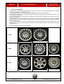
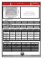
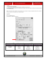
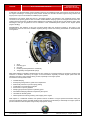
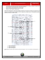
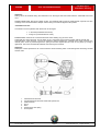
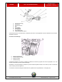
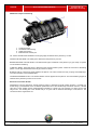
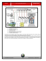
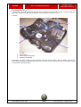
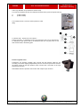
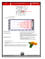
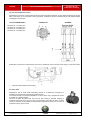
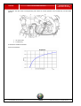
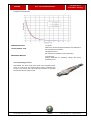
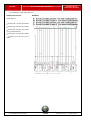
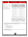
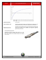
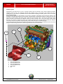
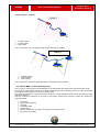
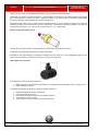
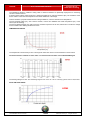
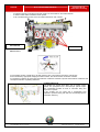
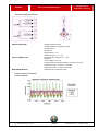
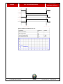
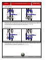
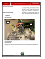
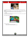
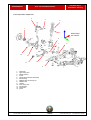
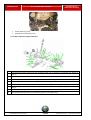
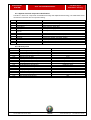
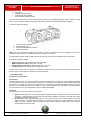
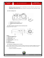
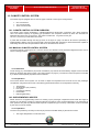
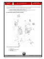
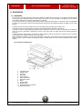
1
ALFA 159 TRAINING MATERIAL Fiat Auto S.p.A. After Sales Training Alfa Romeo 159 Traccia Didattica Alfa 159-en-ridotta 1/318 © 2004 Fiat Auto S.p.A. - All rights reserved ALFA 159 TRAINING MATERIAL Fiat Auto S.p.A. After Sales Training CHANGES/UPDATES Date Ref. File Name Description © 2004 - Fiat Auto S.p.A. All rights reserved. Circulation and reproduction also partial and with any means is forbidden. No liability will be assumed for involuntary mistakes or omissions. Contents may be constantly updated: Fiat Auto S.p.A. cannot be liable for consequences deriving from use of obsolete data. This publication is for training use only. Refer to the service manual and to service bulletins for the concerned vehicle model for complete, up-to-date technical information for servicing purposes. © 2004 Fiat Auto S.p.A. - All rights reserved 2/318 Traccia Didattica Alfa 159-en-ridotta CONTENTS ALFA 159 TRAINING MATERIAL Fiat Auto S.p.A. After Sales Training CONTENTS CONTENTS ..................................................................................................................................................................3 1. BRIEFING.................................................................................................................................................................9 1.1 GENERAL TECHNICAL DATA ............................................................................................................................................. 9 1.1.1 Presentation.............................................................................................................................................................................................9 1.2 THE CAR................................................................................................................................................................................. 9 1.2.1 Style .........................................................................................................................................................................................................9 1.2.2 Dimensions ............................................................................................................................................................................................10 The dimensions in brackets refer to versions fitting 215/55 R16 tyres.......................................................................................................10 1.2.3 Interiors ..................................................................................................................................................................................................10 1.2.4 Outfits and characteristics......................................................................................................................................................................11 1.2.5 Engine versions .....................................................................................................................................................................................11 1.2.6 Transmission..........................................................................................................................................................................................12 The transmissions available at time of release are shown in bold print..........................................................................................................12 1.2.7 Bodyshell ...............................................................................................................................................................................................12 1.2.8 Suspensions ..........................................................................................................................................................................................13 1.2.9 Active safety...........................................................................................................................................................................................14 1.2.10 Passive safety......................................................................................................................................................................................14 1.2.11 Alarm system .......................................................................................................................................................................................16 1.2.12 Tyres and wheels.................................................................................................................................................................................17 1.2.13 Roominess ...........................................................................................................................................................................................18 1.2.14 Climate control system.........................................................................................................................................................................18 1.2.15 Sunroof ................................................................................................................................................................................................19 1.2.16 Sound system ......................................................................................................................................................................................19 1.2.17 Navigator..............................................................................................................................................................................................19 1.2.18 Materials used......................................................................................................................................................................................20 1.2.19 Production process ..............................................................................................................................................................................20 1.2.20 Aerodynamics ......................................................................................................................................................................................21 1.2.21 Anti-corrosion and cosmetic warranty..................................................................................................................................................21 1.2.22 Range ..................................................................................................................................................................................................22 1.2.23 Product grid according to outfit level....................................................................................................................................................23 1.2.24 Lineaccessori .......................................................................................................................................................................................24 2. TECHNICAL DATA .........................................................................................................................................27 2.1 ENGINE.............................................................................................................................................................................. 27 2.1.1 Engine type ............................................................................................................................................................................................27 2.1.2 Engine specifications .............................................................................................................................................................................27 2.1.3 Timing angles.........................................................................................................................................................................................27 2.1.4 Injection/ignition .....................................................................................................................................................................................28 2.1.5 Characteristic curves of the engine .......................................................................................................................................................28 2.1.6 Engine cooling .......................................................................................................................................................................................30 2.2 TRANSMISSION ................................................................................................................................................................ 30 2.3 CLUTCH............................................................................................................................................................................. 30 2.4 GEARBOX.......................................................................................................................................................................... 30 2.5 DIFFERENTIAL .................................................................................................................................................................. 31 2.6 BRAKES............................................................................................................................................................................. 31 2.6.1 Braking system ......................................................................................................................................................................................31 2.6.2 Front brakes...........................................................................................................................................................................................32 2.6.3 Rear brakes ...........................................................................................................................................................................................32 2.7 STEERING ......................................................................................................................................................................... 32 2.8 FRONT SUSPENSIONS .................................................................................................................................................... 33 2.8.1 Helical springs........................................................................................................................................................................................33 2.8.2 Shock absorbers ....................................................................................................................................................................................33 2.8.3 Stabiliser ................................................................................................................................................................................................33 2.9 REAR SUSPENSIONS....................................................................................................................................................... 34 2.9.1 Helical springs........................................................................................................................................................................................34 2.9.2 Shock absorbers ....................................................................................................................................................................................34 2.9.3 Roll bar...................................................................................................................................................................................................34 2.10 TRIM AND CHARACTERISTIC ANGLES ......................................................................................................................... 34 2.10.1 Trim (Std. A conditions) .......................................................................................................................................................................34 2.10.2 Front suspension (Std. A conditions) ...................................................................................................................................................35 2.10.3 Rear suspension (Std. A conditions) ...................................................................................................................................................35 2.11 ALTERNATOR ................................................................................................................................................................. 36 Traccia Didattica Alfa 159-en-ridotta 3/318 © 2004 Fiat Auto S.p.A. - All rights reserved CONTENTS ALFA 159 TRAINING MATERIAL Fiat Auto S.p.A. After Sales Training 2.11.1 Characteristic data............................................................................................................................................................................... 36 2.12 STARTER MOTOR........................................................................................................................................................... 36 2.12.1 Characteristic data............................................................................................................................................................................... 36 2.13 BATTERY ......................................................................................................................................................................... 36 2.14 FLUIDS AND LUBRICANTS ............................................................................................................................................. 36 2.14.1 Oils and fluids ...................................................................................................................................................................................... 36 2.14.2 Greases ............................................................................................................................................................................................... 37 2.14.3 Lubricant capacity................................................................................................................................................................................ 37 2.14.4 Grease amounts .................................................................................................................................................................................. 37 2.15 VEHICLE FEATURES ...................................................................................................................................................... 38 2.15.1 Dimensions .......................................................................................................................................................................................... 38 2.15.2 Performance ........................................................................................................................................................................................ 38 2.15.3 Capacities ............................................................................................................................................................................................ 39 2.15.4 Consumptions...................................................................................................................................................................................... 39 2.15.5 Emissions ............................................................................................................................................................................................ 39 2.15.6 Tyres and inflation pressures (bars) .................................................................................................................................................... 39 2.16 SERVICE SCHEDULE...................................................................................................................................................... 40 3. ENGINE ..................................................................................................................................................................42 3.1 1.9 AND 2.2 LITRE DIRECT INJECTION PETROL ENGINES ............................................................................................ 42 3.1.1 Features ................................................................................................................................................................................................ 42 Engine (suction side).................................................................................................................................................................................. 43 Engine (exhaust side) ................................................................................................................................................................................ 43 Specifications: 1.9 litre engine ................................................................................................................................................................... 43 Specifications: 2.2 litre engine ................................................................................................................................................................... 44 Engine specifications compared ................................................................................................................................................................ 45 Engine performance................................................................................................................................................................................... 46 Code location on engines........................................................................................................................................................................... 46 3.1.2 Engine components ............................................................................................................................................................................... 47 Engine mounts ........................................................................................................................................................................................... 47 Cylinder block............................................................................................................................................................................................. 49 Pistons and connecting rods ...................................................................................................................................................................... 50 Crankshaft.................................................................................................................................................................................................. 51 Flywheel ..................................................................................................................................................................................................... 51 Timing ........................................................................................................................................................................................................ 59 Camshaft.................................................................................................................................................................................................... 60 Drive chains ............................................................................................................................................................................................... 60 Camshaft tensioners .................................................................................................................................................................................. 63 Utility drive belt........................................................................................................................................................................................... 64 Balancing countershafts............................................................................................................................................................................. 65 Continuous cam variable timing system..................................................................................................................................................... 65 Cooling system........................................................................................................................................................................................... 68 Lubrication system ..................................................................................................................................................................................... 70 Blow-by system .......................................................................................................................................................................................... 72 Air intake system........................................................................................................................................................................................ 73 Fuel injection system.................................................................................................................................................................................. 77 Sensors ...................................................................................................................................................................................................... 93 Exhaust system........................................................................................................................................................................................ 110 Exhaust diagram - cold part ..................................................................................................................................................................... 111 3.1.3 Bosch MED 7.6.1 ECU operating logic................................................................................................................................................ 111 3.1.4 Operating strategies ............................................................................................................................................................................ 113 Alfa Code recognition............................................................................................................................................................................... 113 Self-learning ............................................................................................................................................................................................. 114 System self-adaptation............................................................................................................................................................................. 114 Cold start-up control................................................................................................................................................................................. 114 Combustion control - lambda sensors...................................................................................................................................................... 115 Knock control ........................................................................................................................................................................................... 116 Acceleration mixture enrichment control .................................................................................................................................................. 117 Accelerator pedal fuel cut-off ................................................................................................................................................................... 118 Fuel vapour recovery ............................................................................................................................................................................... 119 Maximum engine speed control ............................................................................................................................................................... 120 Fuel pump control .................................................................................................................................................................................... 121 Climate control system connection .......................................................................................................................................................... 122 Cylinder position acknowledgment........................................................................................................................................................... 122 Optimal injection time for each cylinder ................................................................................................................................................... 123 Fan control ............................................................................................................................................................................................... 125 ABS/ASR ECU connection....................................................................................................................................................................... 126 Variable timing management ................................................................................................................................................................... 126 3.1.5 Engine maintenance special tools ....................................................................................................................................................... 128 © 2004 Fiat Auto S.p.A. - All rights reserved 4/318 Traccia Didattica Alfa 159-en-ridotta CONTENTS ALFA 159 TRAINING MATERIAL Fiat Auto S.p.A. After Sales Training 3.2 1.9 / 2.4 MJET DPF ENGINE ............................................................................................................................................ 129 3.2.1 Fuel feed rail (common rail) .................................................................................................................................................................129 Features ...................................................................................................................................................................................................129 Construction .............................................................................................................................................................................................129 Fuel pump ................................................................................................................................................................................................130 Fuel filter...................................................................................................................................................................................................130 3.2.2 Bosch EDC-16C39 electronic control system......................................................................................................................................131 Engine speed sensor................................................................................................................................................................................136 Cam angle (timing) sensor .......................................................................................................................................................................137 Intake air pressure and temperature signal..............................................................................................................................................137 Engine coolant temperature sensor .........................................................................................................................................................138 HFM 6 digital air mass meter ...................................................................................................................................................................138 Motorised throttle......................................................................................................................................................................................143 Fuel pressure sensor................................................................................................................................................................................144 Accelerator pedal potentiometer ..............................................................................................................................................................145 Bosch CP1H high pressure pump ............................................................................................................................................................146 High pressure pump operation .................................................................................................................................................................146 Radialjet pump specifications...................................................................................................................................................................147 Low pressure regulator solenoid valve.....................................................................................................................................................147 Injectors....................................................................................................................................................................................................148 Injector structure.......................................................................................................................................................................................148 IMA injector classification .........................................................................................................................................................................149 Variable geometry intake actuator............................................................................................................................................................149 GARRETT VGT 17 turbo charger ............................................................................................................................................................151 Exhaust gas recirculation system.............................................................................................................................................................153 Bosch EDC-16C39 ECU logic ..................................................................................................................................................................158 Alfa Code recognition ...............................................................................................................................................................................158 3.2.3 Electrical features of sensor ................................................................................................................................................................174 Tachometer sensor electrical features .....................................................................................................................................................174 Timing sensor electrical features..............................................................................................................................................................175 Timing sensor electrical features..............................................................................................................................................................175 Supercharger sensor features..................................................................................................................................................................176 Coolant temperature sensor electrical features........................................................................................................................................177 Air mass meter .........................................................................................................................................................................................177 Fuel pressure sensor................................................................................................................................................................................178 Accelerator pedal potentiometer ..............................................................................................................................................................179 Electrical features of actuators .................................................................................................................................................................179 3.2.4 Injector .................................................................................................................................................................................................180 VGT solenoid valve ..................................................................................................................................................................................181 Fuel pump ................................................................................................................................................................................................181 Glow plug pre-heater ECU .......................................................................................................................................................................182 4. CLUTCH ...............................................................................................................................................................185 4.2 CLUTCH ASSEMBLY....................................................................................................................................................... 185 4.2. “XTEND” plate wear take-up device ......................................................................................................................................................185 4.2.2 Driven friction plate ..............................................................................................................................................................................189 4.3 VALEO CLUTCH .............................................................................................................................................................. 189 4.3.1 Clutch assembly...................................................................................................................................................................................189 4.3.2 “SAT” (Self Adjusting Technology) plate wear take-up system ...........................................................................................................189 4.3.3 Driven friction plate ..............................................................................................................................................................................191 4.4 LUK FLYWHEEL/CLUTCH............................................................................................................................................... 192 4.4.1 Dual mass flywheel ..............................................................................................................................................................................192 4.4.2 Clutch assembly...................................................................................................................................................................................194 4.5 CLUTCH RELEASE.......................................................................................................................................................... 197 5. M32 GEARBOX....................................................................................................................................................198 5.1 FEATURES ...................................................................................................................................................................... 198 5.1.1 Gearbox interfaces...............................................................................................................................................................................199 5.1.2 Transmission ratios..............................................................................................................................................................................200 5.2 GEARBOX STRUCTURE................................................................................................................................................. 200 5.2.1 Meshing diagram .................................................................................................................................................................................201 First and second gear...............................................................................................................................................................................201 Third and fourth gear................................................................................................................................................................................202 Fifth and sixth gear...................................................................................................................................................................................202 Reverse ....................................................................................................................................................................................................203 5.2.2 Gears ...................................................................................................................................................................................................203 5.2.3 Shafts...................................................................................................................................................................................................203 Primary shaft ............................................................................................................................................................................................203 Upper secondary shaft .............................................................................................................................................................................204 Traccia Didattica Alfa 159-en-ridotta 5/318 © 2004 Fiat Auto S.p.A. - All rights reserved CONTENTS ALFA 159 TRAINING MATERIAL Fiat Auto S.p.A. After Sales Training Lower secondary shaft ............................................................................................................................................................................. 204 5.2.4 Synchronisers ...................................................................................................................................................................................... 205 5.2.5 Mounts ................................................................................................................................................................................................. 206 Gear shifting system ................................................................................................................................................................................ 206 5.2.6 Differential ........................................................................................................................................................................................... 207 5.2.7 Axle shafts ........................................................................................................................................................................................... 207 Axle shaft structure .................................................................................................................................................................................. 208 Tripod joint ............................................................................................................................................................................................... 208 6. BRAKING SYSTEM .............................................................................................................................................210 6.1 FEATURES ...................................................................................................................................................................... 210 6.1.1 Braking system components ............................................................................................................................................................... 210 Pedal board.............................................................................................................................................................................................. 210 Brake booster........................................................................................................................................................................................... 211 Brake actuators ........................................................................................................................................................................................ 212 6.1.2 ABS...................................................................................................................................................................................................... 213 Electro-hydraulic control unit.................................................................................................................................................................... 213 6.1.3 ABS wiring diagram ............................................................................................................................................................................. 215 Speed sensor ........................................................................................................................................................................................... 215 6.1.4 EBD function........................................................................................................................................................................................ 216 6.2 VDC SYSTEM................................................................................................................................................................... 216 Electro-hydraulic control unit.................................................................................................................................................................... 216 6.2.2 VDC wiring diagram............................................................................................................................................................................. 217 Steering angle sensor (SAS) and steering angle node (NAS) ................................................................................................................. 218 Yaw/lateral acceleration sensor ............................................................................................................................................................... 219 6.2.3 Hill Holder ............................................................................................................................................................................................ 220 6.2.4 ASR/TCS/MSR .................................................................................................................................................................................... 222 Hydraulic Brake Assist.................................................................................................................................................................................. 223 VDC signals .................................................................................................................................................................................................. 223 Warning light functions............................................................................................................................................................................. 223 6.2.8 ASR and VDC deactivation ................................................................................................................................................................. 224 7. STEERING............................................................................................................................................................225 7.1 FEATURES ...................................................................................................................................................................... 225 7.1.1 Hydraulic system ................................................................................................................................................................................. 225 7.1.2 Steering system components .............................................................................................................................................................. 226 7.1.3 Steering box ........................................................................................................................................................................................ 226 7.1.4 Steering column................................................................................................................................................................................... 227 7.1.5 Yield point fastening ............................................................................................................................................................................ 227 8. SUSPENSIONS ....................................................................................................................................................228 8.1 FEATURES ...................................................................................................................................................................... 228 8.1.1 Front suspension ................................................................................................................................................................................. 228 Front suspension components ................................................................................................................................................................. 229 8.1.2 Rear suspensions ................................................................................................................................................................................ 234 Rear suspension components.................................................................................................................................................................. 234 8.1.3 Rear suspension yield fasteners ......................................................................................................................................................... 236 8.1.4 Angle and vehicle trim inspections ...................................................................................................................................................... 238 8.1.5 Geometrical trim adjustment................................................................................................................................................................ 239 Front suspension...................................................................................................................................................................................... 239 Rear suspension ...................................................................................................................................................................................... 240 9. ELECTRICAL SYSTEM .......................................................................................................................................241 9.1 OVERVIEW OF THE ELECTRICAL SYSTEM .................................................................................................................. 241 9.1.1 The Mini F.L.Ore.N.C.E architecture ................................................................................................................................................... 241 9.1.2 Electrical system layout ....................................................................................................................................................................... 242 9.1.3 System electrical component classification ......................................................................................................................................... 243 9.1.4 Ground points ...................................................................................................................................................................................... 243 9.1.5 Electronic components ........................................................................................................................................................................ 244 9.1.6 User control modules........................................................................................................................................................................... 245 9.1.7 Fuse and relay box .............................................................................................................................................................................. 245 9.1.8 Networks and serial lines..................................................................................................................................................................... 245 9.1.9 The LIN concept .................................................................................................................................................................................. 245 9.1.10 Fuses ................................................................................................................................................................................................. 246 9.1.11 ‘Mini F.L.Ore.N.C.E.’ architecture diagram........................................................................................................................................ 249 9.1.12 Diagnostic architecture ...................................................................................................................................................................... 252 9.1.13 Logistic mode function....................................................................................................................................................................... 253 9.2 TRW SMART KEY SYSTEM............................................................................................................................................. 255 © 2004 Fiat Auto S.p.A. - All rights reserved 6/318 Traccia Didattica Alfa 159-en-ridotta CONTENTS ALFA 159 TRAINING MATERIAL Fiat Auto S.p.A. After Sales Training 9.2.1 Functions .............................................................................................................................................................................................255 9.2.2 Structure ..............................................................................................................................................................................................255 9.2.3 Operative procedures ..........................................................................................................................................................................256 9.2.4 Overview of fundamental operations ...................................................................................................................................................259 9.2.5 Code system programming and component management..................................................................................................................260 9.2.6 Procedures for replacing components .................................................................................................................................................261 9.2.7 NTR diagnostic procedures .................................................................................................................................................................262 9.3 ON-BOARD INSTRUMENTS ........................................................................................................................................... 266 9.3.1 HIGH and MEDIUM instrument panels ................................................................................................................................................266 9.3.2 BASIC instrument panels.....................................................................................................................................................................268 9.3.3 Notions on the Service function ...........................................................................................................................................................269 9.4 COMPUTERISED SYSTEMS........................................................................................................................................... 272 9.4.1 Connect NAV+ .....................................................................................................................................................................................272 9.4.2 CONNECT button (A) ..........................................................................................................................................................................275 9.5 TYRE PRESSURE DETECTION SYSTEM ...................................................................................................................... 276 9.5.1 Overview ..............................................................................................................................................................................................276 9.5.2 Structure ..............................................................................................................................................................................................276 9.5.3 Operation .............................................................................................................................................................................................277 9.5.4 TPMS deactivation...............................................................................................................................................................................277 9.5.5 Tyre pressure monitoring system ........................................................................................................................................................278 9.5.6 Initiator .................................................................................................................................................................................................278 9.5.7 Control unit...........................................................................................................................................................................................278 9.5.8 Operating details..................................................................................................................................................................................278 9.5.9 Key-on/key-off strategies .....................................................................................................................................................................279 9.6 PARKING ASSISTANCE.................................................................................................................................................. 280 9.6.1 Notions for calculating distance from obstacles...................................................................................................................................280 9.6.2 Structure ..............................................................................................................................................................................................281 9.6.3 Electronic control unit ..........................................................................................................................................................................281 9.6.4 Ultrasound sensors ..............................................................................................................................................................................281 9.6.5 Buzzers ................................................................................................................................................................................................281 9.6.6 Switching the system on and off ..........................................................................................................................................................281 9.6.7 Coverage area .....................................................................................................................................................................................282 9.6.8 Diagnostics ..........................................................................................................................................................................................282 9.6.9 Component characteristics ..................................................................................................................................................................282 9.6.10 ECU pinout.........................................................................................................................................................................................283 9.6.11 Ultrasound sensor..............................................................................................................................................................................284 9.7 AIRBAGS ......................................................................................................................................................................... 284 9.6.1 Overview ..............................................................................................................................................................................................284 9.7.2 Airbag system diagram ........................................................................................................................................................................284 9.7.3 Knee airbag modules ...........................................................................................................................................................................285 9.7.4 Front seat belt pretensioners ...............................................................................................................................................................286 9.7.5 Front seat belt reminder sensors .........................................................................................................................................................286 9.7.6 Airbag system warning lights ...............................................................................................................................................................286 9.7.7 Airbag system failure warning light ......................................................................................................................................................287 9.7.8 Passenger airbag deactivated warning light ........................................................................................................................................287 9.7.9 Seat belt reminder................................................................................................................................................................................287 9.7.10 Clock contact pinout...........................................................................................................................................................................288 9.8 FRONT LIGHT CLUSTER (XENON GAS DISCHARGE VERSION) .............................................................................................. 290 9.8.1 Xenon bulb...........................................................................................................................................................................................291 9.8.2 Rear headlight view .............................................................................................................................................................................292 9.8.3 Wiring diagram and optical cluster connector pinout ...........................................................................................................................292 9.8.4 Automatic headlight position corrector.................................................................................................................................................292 9.8.5 Adjustment actuator .............................................................................................................................................................................293 9.8.6 Self-diagnostics....................................................................................................................................................................................294 9.8.7 Recovery..............................................................................................................................................................................................294 9.8.8 Resetting..............................................................................................................................................................................................294 10. CLIMATE CONTROL SYSTEM .........................................................................................................................295 10.1 CLIMATE CONTROL SYSTEM OVERVIEW .................................................................................................................. 295 10.2 MANUAL CLIMATE CONTROL SYSTEM ...................................................................................................................... 295 10.2.1 Structure ............................................................................................................................................................................................295 10.2.2 Operation ...........................................................................................................................................................................................295 10.3 SUPPLEMENTARY HEATER......................................................................................................................................... 295 10.3.1 Operation ...........................................................................................................................................................................................295 10.4 ONE-ZONE CLIMATE CONTROL SYSTEM................................................................................................................... 296 10.4.1 One-zone climate control system wiring diagram ..............................................................................................................................297 10.5 TWO AND THREE-ZONE AUTOMATIC CLIMATE CONTROL SYSTEM ................................................................ 298 10.5.1 Two-zone system...............................................................................................................................................................................298 10.5.2 Front two/three-zone controls ............................................................................................................................................................298 Traccia Didattica Alfa 159-en-ridotta 7/318 © 2004 Fiat Auto S.p.A. - All rights reserved CONTENTS ALFA 159 TRAINING MATERIAL Fiat Auto S.p.A. After Sales Training 10.5.3 Three-zone system............................................................................................................................................................................ 298 10.5.4 Rear three-zone controls ................................................................................................................................................................... 298 10.5.5 Notes on sensor operation ................................................................................................................................................................ 299 10.5.6 Two/three-zone climate control system ............................................................................................................................................. 300 10.5.7 Two/three-zone climate control system wiring diagram..................................................................................................................... 302 One-zone ECU pinout .............................................................................................................................................................................. 303 Two/three-zone ECU pinout..................................................................................................................................................................... 304 10.5.8 Head control rear connector pinout ................................................................................................................................................... 304 11. BODYWORK ......................................................................................................................................................305 11.1 SUNROOF...................................................................................................................................................................... 305 11.1.1 Sunroof components ......................................................................................................................................................................... 305 11.1.2 Operation of the sunroof .................................................................................................................................................................... 306 11.1.3 Operating logic .................................................................................................................................................................................. 306 Manual control via pre-selector ................................................................................................................................................................ 307 Remote control......................................................................................................................................................................................... 307 Notes........................................................................................................................................................................................................ 307 Pinch force safety function ....................................................................................................................................................................... 308 11.1.4 Emergency operation ........................................................................................................................................................................ 308 11.1.5 Initialisation procedure....................................................................................................................................................................... 308 11.1.6 Wiring diagram .................................................................................................................................................................................. 309 11.2 SEATS............................................................................................................................................................................ 309 11.2.1 Features of the seats ......................................................................................................................................................................... 309 Front seats ............................................................................................................................................................................................... 309 Rear seats................................................................................................................................................................................................ 311 11.2.2 Front seat structure ........................................................................................................................................................................... 312 Anti-whiplash system ............................................................................................................................................................................... 312 11.2.3 Electrically adjustable seats .............................................................................................................................................................. 313 Electrical seat diagrams ........................................................................................................................................................................... 314 Passenger presence sensor (SBR).......................................................................................................................................................... 317 Seat operation.......................................................................................................................................................................................... 317 © 2004 Fiat Auto S.p.A. - All rights reserved 8/318 Traccia Didattica Alfa 159-en-ridotta BRIEFING Fiat Auto S.p.A. After Sales Training ALFA 159 TRAINING MATERIAL 1. BRIEFING 1.1 GENERAL TECHNICAL DATA 1.1.1 Presentation Alfa Romeo 159 is the first of a new generation of Alfa Romeo cars. Stemming from the long, consolidated experience of Alfa Romeo in the top-of-the-range sports car and appealing coupe range, the ‘Alfa Romeo 159’ project implements innovative engineering methods to maximise the skills of an international team and uncompromisingly combine performance and objectives until before deemed difficultly compatible (maximum driving pleasure, high performance, distinctive style with top safety, comfort and robustness). This all led to the creation of a new bodyshell with unprecedented suspensions and a new generation of engines and transmissions. The Alfa 159 underwent a very demanding reliability test cycle: eighty-five cars clocked a total of 4,250 million kilometres on all types of road and in all weather conditions for timely analysis and solution of all anomalies arising during development. To increase driving pleasure and safety to absolute levels, the Alfa 159 engineers developed a sophisticated fourwheel drive system (some versions only) which enhances the car’s already superlative dynamic performance and increases safety, especially in poor grip conditions. Alfa Romeo has always meant continuous research and innovation combined with a glorious racing tradition, based on the work and professional pride of thousands of individuals - technicians, factory workers, managers - who have worked in the factories, in the offices and on the race tracks in the course of time. These are the roots of the incomparable personality that makes an Alfa Romeo stand out among all the other cars on road. 1.2 The car 1.2.1 Style Designed by Giorgetto Giugiaro in collaboration with the Alfa Romeo Styling Centre, the new car has a number of distinctive features that highlight its strong personality and make it immediately recognisable, in the best Alfa tradition. Starting from the front, which is strong and dynamic, dominated by the Alfa Romeo family feeling of the characteristic ‘cloverleaf’ sporting the large shield. The line of the entire car springs from here, combining a light stylistic 'aggressiveness' with strikingly elegant forms: an impression that is underlined by the light clusters, which are delightful design features. The trapezoid shape of the front accentuates the car's sensation of solidity, highlighted by the way the passenger compartment rests on a powerful 'shoulder'. This runs all along the waistline of the car, broadening considerably when it reaches the rear pillar. This pillar has a double stylistic function: it links to the curve of the rear window, above the rear axle (another clear stylistic expression of strength, robustness and dynamism), and embraces the passenger compartment thanks to the stylistic device of the classic Alfa Romeo 'elbow'. The front pillar is set further back to make the line look sleeker, underlining the presence of the powerful engine, and making the passenger compartment look more compact, improving visibility on bends. Traccia Didattica Alfa 159-en-ridotta 9/318 © 2004 Fiat Auto S.p.A. - All rights reserved BRIEFING Fiat Auto S.p.A. After Sales Training ALFA 159 TRAINING MATERIAL In other words, sleek but solid, dynamic but robust: only outstanding stylistic balance can combine such different characteristics. For example the 'muscular' wing which, next to the generous wheels, marks the widest point of the car, unequivocally conveys the ideal of a car that is firmly 'anchored to the ground'. In spite of its capacious size, the rear-end, with its beautifully balanced form, blends perfectly with the front, setting off its unique personality, and has a horizontal design, underlined by a chromed double exhaust tailpipe on the more powerful versions. And it is topped off by a small spoiler which combines styling and practicality, right above the logo which is positioned where it is immediately visible, and the elongated lights, divided by the slit of the boot, which include cylindrical shapes derived from the styling of the front headlights. And finally, the new model offers a choice of 14 different colours. 1.2.2 Dimensions The dimensions in brackets refer to versions fitting 215/55 R16 tyres. The 159 is bigger than the 156: 159 156 Length [mm] 4661 4430 + 231 Width [mm] 1828 1745 + 83 Height [mm] 1422 1415 +7 Wheelbase [mm] 2701 2595 + 106 1.2.3 Interiors The interior of the Alfa Romeo 159 also represents an evolved expression of the sportiness and elegance embodied by Alfa. It was defined around the driving position, focusing attention on the driver: excellent ratios for the distances between pedals, seat, steering wheel and gearlever give the driver a sense of total control over the car, which produces the enjoyable driving so typical of Alfa Romeo. The facia and wraparound centre console incorporate all the driving instruments and are turned ergonomically towards the driver. The speedometer, rev counter and other instruments, all strictly analogue, are circular with clear, refined, extremely legible graphics. The anti-glare lip accentuates the 'boat' shape of the main instruments, confirming a feature peculiar to Alfa Romeo design that is based on a deep-rooted attention to volumes and mature treatment of surfaces. To underline the functional continuity between the facia and the console, the designers aimed to achieve stylistic continuity between them: the console, which is raised as if stretching towards the facia, has a sporty gearlever with short, precise movements, and a comfortable armrest that incorporates a large insulated storage compartment. © 2004 Fiat Auto S.p.A. - All rights reserved 10/318 Traccia Didattica Alfa 159-en-ridotta BRIEFING ALFA 159 TRAINING MATERIAL Fiat Auto S.p.A. After Sales Training The interior achieves a perfect balance between elegance and sportiness, an equation that Alfa Romeo translates into refined colour combinations, quality fabrics, precious fine grain leather and luxurious materials (like the aluminium mouldings). The range includes three specification levels, each featuring specific 'natural' interior upholstery. The sophisticated technology with which the facia was made, guarantees a refined opaque effect and a surface that is soft to the touch. The customer will appreciate the wraparound, finely modelled seats, which are made with carefully selected materials paying great attention to the details. The passenger compartment has fourteen storage compartments (the 156 had eleven) to fully meet the customer’s needs. A great deal of emphasis was placed on improving the quality of air in the passenger compartment by choosing low emission materials. The odour level of the Alfa 159 was analysed: a team of experts were asked to ‘smell’ the car while is was being developed to ensure a constantly excellence olfactory perception. 1.2.4 Outfits and characteristics The main contents of the various outfits are illustrated below. The outfits are called L1, L2, L3 in brief. L1 is the basic version, L2 is the medium version and L3 is the most prestigious version. This classification is only used is this training material to avoid mentioning commercial names which may change in time. L1 outfit ¾ ¾ ¾ ¾ Seven airbags Manual climate control system 16” rims Tyre kit (deflated wheel and compressor) L2 outfit The following features are added to the L1 outfit: ¾ ¾ ¾ ¾ ¾ ¾ ¾ ¾ ¾ ¾ Eight-speaker sound system with CD player Fog lights Trip computer Ski compartment + rear armrest Leather steering wheel and gearlever knob Reconfigurable display instrument panel Flocked upholstery Double compartment central console (one of which insulated) Painted dome mirrors Shiny tailpipe ¾ ¾ ¾ ¾ ¾ ¾ ¾ ¾ Two-zone automatic climate control system AQS, rain sensor Rear electric windows with pinch force safety function Cruise control Electrochromic interior rear view mirror Sound system controls on steering wheel Alfatex upholstery Aluminium interior accents L3 outfit 1.2.5 Engine versions The Alfa 159 fit state-of-the-art petrol and diesel engines. Three new JTS engines with continuous dual variable valve timing (inlet and exhaust) are available. All the engines have outstanding features and meet Euro 4 standards, exploiting the direct petrol injection in full, a particular combustion system known as JTS (Jet Thrust Stoichiometric). Traccia Didattica Alfa 159-en-ridotta 11/318 © 2004 Fiat Auto S.p.A. - All rights reserved BRIEFING ALFA 159 TRAINING MATERIAL Fiat Auto S.p.A. After Sales Training Alfa Romeo has always been on the leading edge in the field of diesel engines. All engines are with Multijet technology, turbo charging is entrusted to a variable geometry turbo and intercooler. The 1.9 M-jet exploits a specific turbine developed by Alfa Romeo while the 2.4 M-jet has a new cylinder head and new ‘fracture-split’ steel connecting rods. The three engines all meet Euro 4 requirements and incorporate a standard particulate trap (DPF) which considerably reduces the particulate contained in exhaust gas. Alfa 159 engines are ¾ ¾ ¾ ¾ ¾ ¾ ¾ 1.8 16V 130 HP (96 kW) 1.9 16V JTS 160 HP (118 kW) 2.2 16V JTS 185 HP (136 kW) 1.9 M-jet 8V 120 HP (88 kW) 1.9 M-jet 150 HP (110 kW) 2.4 M-jet 200 HP(147 kW) 3.0 V6 M-jet 250 HP (185 kW) The engine versions available at time of release are shown in bold print. 1.2.6 Transmission The Alfa 159 fits the following transmissions to best exploit the engine features: ¾ ¾ ¾ ¾ M32 six manual gears for 1.9/2.2 JTS, 1.9 8/16V M-jet F40 six manual gears for 2.4 Multijet 200 HP M32 six speed Selespeed for 1.9 JTS AISIN AF40 six speed automatic for 2.4 M-jet, 3.0 V6 M-jet and 3.2 V6 The transmissions available at time of release are shown in bold print. 1.2.7 Bodyshell The new Alfa 159 bodyshell, developed specifically for the ‘Premium’ platform in collaboration with GM, presents radical architectural innovations with respect to the previous 156 chassis. The bodyshell has various longitudinal boxed elements that are reciprocally connected by transversal elements completed by the dashboard and floor panels. The floor pan boxed elements seamlessly integrate the body elements and form a perfectly integrated structure. The energy of a front or rear-end collision is mainly absorbed by the two load lines formed by the front struts, the chassis, the engine mount system, the rear struts, the sidemembers under the floor and the sidemembers. The continuity between these parts, for the entire length of the car, ensures gradual, progressive distortion. Furthermore, the connection between struts and suspension-engine chassis contributes to the optimal distribution of the load front towards distortable obstacles. The high strength material and differentiated thickness of the appropriately dimensioned front and rear sidemembers support the force developed by the front and rear crossmembers in low speed collisions without being damaged. At the same time, they entirely absorb the energy of high speed collisions without distorting the passenger compartment. © 2004 Fiat Auto S.p.A. - All rights reserved 12/318 Traccia Didattica Alfa 159-en-ridotta BRIEFING Fiat Auto S.p.A. After Sales Training ALFA 159 TRAINING MATERIAL The front fits a boxed crossmember with controlled distortion collapsible mounts (called ‘crash-box’); the rear fits a very thick crossmember with collapsible open section. Both crossmembers are made of high strength steel and are screws onto the floor pan for easier replacement. CRASH BOX A specific ‘gantry’ boxed structure is fastened behind the rear seat backrest: this is structural element of primary importance for obtaining torsional stiffness of the body. The result is the excellent torsional rigidity of the bodyshell: over 180.000 daNm/rad (given a torsional stiffness of 156 equal to approximately 100,000 daNm/rad). ‘Gantry’ boxed structure Both sides of all bodyshell structural elements are galvanised. Some panelling has thicker galvanised coatings to prevent rusting and ensure structural performance for the car’s entire lifespan. 1.2.8 Suspensions The suspensions let the car face all types of terrain by reducing roll and pitch of the chassis, damping vertical stress and constantly maintaining the maximum grip of the wheels on the ground. They must therefore ensure comfort for passengers, driveability and road-hold: bodyshell movements are limited and pleasant. Alfa Romeo puts the accent on handling, i.e. prompt response to commands, precision, steering progression, high stability and control in limit conditions. The Alfa 159 suspensions where designed to become a new, absolute reference in the balance between handling and comfort. The front high quadrilateral suspension arrangement implements the best features of the 156 which has already shown its worth. The many improvements concern the longitudinal filtering and damping capacity which increases lateral stiffness and camber take-up to ensure better grip of the tyre to the ground in limit conditions. Reduced static camber and higher riser-hub stiffness provide a more effective tyre wear. A multilink architecture was chosen for the rear suspension. Also in this case, longitudinal filtering and damping are ensured by a hydraulic bushing and transversal leaf architecture specifically designed to provide superior comfort. The extreme lateral stiffness and the high camber takeup ensure the best handling. Control is ensured by four two-tube shock absorbers with coaxial spring. Traccia Didattica Alfa 159-en-ridotta 13/318 © 2004 Fiat Auto S.p.A. - All rights reserved BRIEFING ALFA 159 TRAINING MATERIAL Fiat Auto S.p.A. After Sales Training The handling-comfort objectives of the Alfa 159 set a new, superior reference, by providing the dynamic performance and passive safety of a smaller, lighter model, like the Alfa 156 (the current reference for the segment), combined with the typical comfort performance of a higher range model. This result was obtained in the course of a three-year fine-tuning process. The tests conducted on various terrain and tracks around the world were exploited to refine all suspension components and implement the changes needed to obtain the required performance regardless of conditions of use. 1.2.9 Active safety The Alfa Romeo 159 is equipped with some of the most sophisticated electronic and mechanical assistance systems: ¾ ¾ ¾ ¾ ¾ ¾ ¾ ABS: wheel anti-locking system EBD: electronic brake distributor between the front and rear wheels VDC: vehicle stability electronic control ASR: traction control system combining the action of brakes and engine ECU MSR: engine brake control governed by the engine ECU HBA (with VDC): automatic braking pressure in the event of panic braking Hill-holder (with VDC): auxiliary system for holding the car stationary when starting uphill: the brakes are released when the car starts off. The servo-hydraulic braking system consists of two independent crossed circuits. Each circuit works on a front wheel and the diagonally opposite rear wheel to ensure braking and stability also in the event of a failure to one of the circuits. The Alfa Romeo 159 fits a pedal board with plastic mount housing the brake and clutch pedals. The clutch pedal is made of plastic. The brake pedal (made of steel) is fitted with a device that makes the pedal board collapse in a collision. This minimises intrusion in the passenger compartment and prevents injuries to the lower limbs. 1.2.10 Passive safety The striving for excellence in performance has led to the introduction of state-of-the-art passive safety design, construction and content solutions. Fiat Auto and suppliers were called upon to take part in a firstly virtual and then experimental test plan at the Orbassano Safety Centre that can be summed up in the following figures: 150 crash tests 100 HYGE sled crash simulations 200 tests on components and subsystems 10 new performance specifications and test procedures 8 specific passive safety structure co-designer suppliers, 3 of whom exclusively involved in designing and making safety devices Occupant protection system The occupant protection system consists of the following parts which are standard for all outfits: ¾ ¾ ¾ A Multistage frontal protection system consists of: ECU, dual stage driver and passenger front airbag, driver and passenger knee airbag, front seatbelts with pretensioner and load limiter in winder, safety sensor on front tunnel, additional peripheral crash sensor on headlight crossbeam, front seatbelt fastening reminder, front seat occupant presence sensor and manual passenger airbag deactivation switch. A chest and hip lateral protection system consisting of: two side airbags in front seats, two window bags in roof sidemembers. Three-point seatbelts for all three rear seats. In other words, the components inside the passenger compartment are all designed to ensure maximum protection for occupants. © 2004 Fiat Auto S.p.A. - All rights reserved 14/318 Traccia Didattica Alfa 159-en-ridotta BRIEFING ALFA 159 TRAINING MATERIAL Fiat Auto S.p.A. After Sales Training Front seats The front seat structure was designed to help and integrate the protection offered by the system. Two robust, coaxial tubes arranged at the front, and one at the back, covered by the front seat cushion, restrain the occupant correctly in frontal collisions and minimise seat distortion in lateral collisions. The front tube and PPE (polypropylene) block embedded in the foam of the cushion protect from the so-called “anti-submarining” effect, that is prevent the occupant from slipping underneath the seatbelt. A robust two-sided hinge between the backrest and the bottom was designed to optimise restraining performance in low speed, rear-end collisions. This feature, in combination with appropriately lighter side panel areas, gradually absorb the energy of high speed, rear-end collisions in a controlled fashion. Rear seats The backrest frame has a tough tubular structure and is designed to withstand the forces of a frontal collision with occupants on the rear seat and/or loads in the boot. The front part of the cushion presents a raised reinforcement to prevent submarining also for rear seat passengers. Two ISOFIX mountings for child safety seats are standard for all outfits on the side rear seats. These anchoring devices have two peculiarities: ¾ ¾ they incentive continuous and correct use the child safety seat providing two fasteners on which to clip and anchor the child safety seat they standardise the dimensions of attachments and their distance so that the child safety seat can be used on any type of vehicle. ISOFIX mountings are therefore characterised by standard dimensions and reciprocal distance. These mountings are firmly installed on rear seat backrests. The robustness of the backrest and the bodyshell anchoring ensure correct use of the child safety seat in all collisions, therefore offering adequate protection to the child. Head restraints All outfits fit standard, height adjustable, locking head restraints on front seats and three head restraints on rear seats. Some Alfa 159 versions also fit an ‘anti-whiplash’ device that in the event of rear-end collisions move the head restraint towards the occupant’s neck. Traccia Didattica Alfa 159-en-ridotta 15/318 © 2004 Fiat Auto S.p.A. - All rights reserved BRIEFING ALFA 159 TRAINING MATERIAL Fiat Auto S.p.A. After Sales Training Dashboard The constraints deriving from correct set-up in passive safety perspective was taken into account for designing the dashboard. The passenger airbag flap is on the top of the dashboard is positioned to make it impossible to place objects on top which could be thrown about if the airbag is deployed. This arrangement also ensures that the passenger’s airbag is inflated towards the windscreen rather than towards the occupant and only later stretches into the position where it provides the best protection. The lower part of the dashboard is designed to ensure that there is no contact between the occupants’ knees and hard parts which could cause injury to lower limbs in a frontal collision. Furthermore, this risk is additionally reduced by the presence of a knee bag. The area underneath the steering column, typically the most dangerous for knees, is protected by an energy absorber arranged between the column and the upholstery. The retractable steering column angular adjustment lever and the absence of an ignition switch block (the vehicle is fitted with a standard electrical steering lock and the start button is located on the dashboard) additionally reduce the possible areas of contact with the driver’s knees in a collision. Door panels The arrangement of the functional elements of the panel (i.e. the armrest and the upper part) are designed to ensure correct interaction with occupant’s body in the event of a side collision. The upper part is smooth and soft while the necessary projection of the armrest is made harmless by collapsing at a load level well under that which may cause internal injury. Interior upholstery Interior upholstery is characterised by soft materials with cover also the necessarily stiff parts, such as front seatbelt height adjuster. Fireproof material is used (fire propagation speed slower than 100 mm/min) to limit risks in the event of a fire. Fire protection The entire car, from the bodyshell to the various components, was designed in accordance with the Alfa most recent, strictest fire protection standards. The fuel feed system components are carefully arranged to protect the possible areas concerned by a collision. Furthermore, the layout of the various systems, followed in detail from the beginning, is very protected and referenced to prevent criticalities. Pedestrian protection The style of the front of the car was developed considering pedestrian protection. Shapes are smooth and rounded. No risky projections for pedestrians are present. The wide surface of the bonnet minimises the risk of contact between the pedestrian’s head and the stiff front pillars. Inside the engine compartment, the stiffest components are arranged at a suitable distance from the bonnet to prevent it from absorbing the energy derived from the impact with the pedestrian’s head. 1.2.11 Alarm system The electronic system consists of the following: transmitter, receiver, ECU with siren, volumetric sensors and antilifting sensors. The alarm is armed and disarmed by radiofrequency using electronic keys that send an encrypted, variable code. The electronic alarm monitors: illicit attempt to open doors, bonnet or boot (peripheral protection), operation of the ignition key, cutting of the battery wires, presence of moving bodies inside the passenger compartment (volumetric protection) and anomalous lifting/slanting of the vehicle (for versions/markets where fitted). Volumetric protection can be cut-out. CAUTION. The engine immobilizer function is ensured by the Alfa Romeo Code system which is activated automatically when the key is removed from the switch. The operation of the electronic alarm is adapted at the plant to the standards in force in the various countries. The approval number of the transmitter is marked on the component for respecting the law in the matter of radiofrequency devices in countries where this is required. The code marking may also be written on the transmitter and/or receiver, according to the version/market. © 2004 Fiat Auto S.p.A. - All rights reserved 16/318 Traccia Didattica Alfa 159-en-ridotta BRIEFING ALFA 159 TRAINING MATERIAL Fiat Auto S.p.A. After Sales Training 1.2.12 Tyres and wheels A new family of tyres have been developed for the Alfa 159 to account for technological innovations and to achieve the best balance between handling and comfort. Ten new specifications and four sizes have been developed to form a 16”, 17” and 18” range. The guidelines followed in tyre development include: handling and braking, excellent road hold, also in rainy conditions, good level comfort. The compounds benefit from the most recent research in the sector and offer extraordinary performance on dry, and especially on wet roads. These features, in combination with the suspension design, mean that the later are mainly responsible for filtering noise and vibrations, with considerable advantages on the tyres which provide higher grip and present considerably less wear than the 156. Each tyre type was tested to measure road hold, response, aquaplaning performance, racing performance on the Pirelli track at Vizzola Ticino, braking distance on dry and wet roads, rolling resistance, noise, filtering capacity and wear resistance. The rims created for the Alfa 159 are shown below. 18” RIMS 17” RIMS 16” RIMS Traccia Didattica Alfa 159-en-ridotta 17/318 © 2004 Fiat Auto S.p.A. - All rights reserved BRIEFING ALFA 159 TRAINING MATERIAL Fiat Auto S.p.A. After Sales Training 1.2.13 Roominess The Alfa 159 is bigger than the 156 and consequently roomier. 159 156 PERCENTILE COMPARISON * Front Rear 99º (hmax=1.93 m) 82.5º (hmax=1.83 m) 97.5º (hmax=1.83 m) 70º (hmax=1.80 m) * This term is used in the automotive sector to indicate the dimensions of dummies used to measure the roominess of cars. For roominess tests, the dummies are adjusted according to percentile values (fractions of 100) which represent the percentages of population which fall into certain ranges of measurements. Specific studies conducted by the USA Health Department indicate that ninety-five people out of one hundred are shorter than 1.85 metres. Therefore, “95 percentile” is used to indicate a maximum height of 1.85 metres. Similarly, “50 percentile” indicates a height of 1.75 metres (50% of the population) and “10 percentile” a height of 1.65 metres. In the case of the 159, front percentile of 99% indicates that 1.93 metre tall occupants can comfortably sit in a front seat. The driver’s leg room (37 millimetres more than the 156) has been increased for more comfortable driving positions. The rear leg room has also been increased. The front (+13.7 millimetres) and rear (+32.5 millimetres) door heights have been increased to improve access. The boot capacity has been increased with respect to the 156 to increase versatility. 156 159 1.2.14 Climate control system Three types of climate control systems are available according to the outfit: ¾ ¾ ¾ Manual Two-zone automatic Three-zone automatic The automatic climate control system allow different temperature and air distribution in two or three different areas of the passenger compartment. © 2004 Fiat Auto S.p.A. - All rights reserved 18/318 Traccia Didattica Alfa 159-en-ridotta BRIEFING Fiat Auto S.p.A. After Sales Training ALFA 159 TRAINING MATERIAL 1.2.15 Sunroof The Alfa 159 sunroof is a traditional mobile glass panel which pushes out, slides horizontally and retracts. The mobile panel slides in a specific seat between roof panels. The safety function managed by the ECU protects occupants from movements controlled from inside the vehicle in compliance with Directive 2000/4/EC. It is active during horizontal closing (front edge) and vertical closing (rear edge) and trips when an obstacle (e.g. finger, hand) is encountered. The possibility of being pinched between the sides of the sunroof is prevented by adopting side guards which block access to dangerous areas. 1.2.16 Sound system The available sound systems are: Standard system: eight speakers, four 165 mm, 40 W mid-woofers and four 30 W tweeters, positioned in the sides (front and rear doors) and on the dashboard. BOSE Hi-Fi sound system: nine speakers plus two amplifiers arranged in different locations according to version (saloon and SportWagon, a sub-woofer with six channel power amplifier is positioned in the boot, bass box with amplifier is positioned in the boot of the SportWagon version while a 10” woofer is positioned on the rear window shelf of the saloon version). The speakers (four 165 mm, 45 W mid-woofers, four 40 mm, 40 W tweeters and a 80 mm 25 W speaker) are designed for the best sound conditions inside the car. All speakers are water-resistant. Sound sources are: Radio or Radio Navigator CD player, MP3 player and CD changer. ¾ ¾ 1.2.17 Navigator The Alfa 159 continuous Alfa’s best tradition in terms of complete, full, computerised contents. Various levels are available to suit all needs: ¾ ¾ ¾ ¾ ¾ Traditional telephone setup Bluetooth telephone connection (Convergence) Map radio navigator (RN) Map radio navigator with integrated free-hands telephone (RNT) Connect Nav+ (radio navigator and telephone with information and rescue services) The map radio navigator (with and without telephone) derives from Connect Nav+ and has the same navigation and audio features. The two devices differ for the absence of computerised services and for the absence of the integrated telephone and hands-free kit (the latter for RN). ‘Convergence’ is an innovative electronic module for interfacing the computer with a Bluetooth cellular phone within the operating range of the system (approximately 5 metres). The interaction method of the system consists of the following devices: ¾ ¾ ¾ Microphone in ceiling light Controls on steering wheel connected via CAN Monochromatic display on on-board panel connected via CAN. The system provides effective and intuitive access to the following functions: ¾ ¾ ¾ ¾ ¾ Hands-free cellular phone use without needing to operate the telephone itself (i.e. the telephone needs to be inside the car but not necessarily in the user’s hands). Voice recognition call (in ‘Speaker dependent’ and ‘Speaker independent’ modes). Copying of personal numbers from telephone to on-board module and reading from on-board panel. Display interaction for called numbers, incoming calls and incoming text messages. Access to normal telephone functions (answer, reject calls, recall back number, etc.) using buttons on the steering wheel. Traccia Didattica Alfa 159-en-ridotta 19/318 © 2004 Fiat Auto S.p.A. - All rights reserved BRIEFING Fiat Auto S.p.A. After Sales Training ALFA 159 TRAINING MATERIAL 1.2.18 Materials used The Alfa 159 is environmental-friendly, down to the chose of materials, machining processes and recyclability. It was built without harmful substances, such as asbestos, chromium, cadmium and CFC, which are replaced with Kevlar, organic pigments, aluminium, zinc and water, respectively. What is more, material used were chosen by applying a LCA (Life Cycle Assessment) process. In line with what will become mandatory for all industrial processes in the future, the method accounts for the global environmental impact of materials in addition to their engineering and industrial characteristics: from extraction of raw materials to disposal after use, including transformation, machining, packing, transportation, use and recycling. Being reassured that the only materials which were harmless for the environment were used to make the new model and that emissions were reduced to the minimum, Alfa Romeo focused on the recyclability of the various parts of the 159 when it reaches the end of its working life. To obtain these important results, the materials were carefully chosen from the beginning of the new Alfa 159 project, for example, by decreasing the number of polymers used and by favouring the use of more easily recyclable plastics. 1.2.19 Production process The roof is laser spot welded to the bodyshell for a total of 2.8 metres of welding: this is the first time that this solution has been adopted by Fiat Auto. This ensures perfect coupling along the entire length of the roof and particularly the possibility of larger resistant sections (laser welding is applied to one side of the panel, the other side can be boxed) for superior performance. OUTER ROOF SIDE OUTER SIDE ROOF ASSEMBLY SEAM The laser welding technology (Agilaser Comau patent) is used on Alfa 159 also for the doors, which benefit from the same advantages providing flatter, more homogenous panels. The roof laser welding cabin © 2004 Fiat Auto S.p.A. - All rights reserved 20/318 Traccia Didattica Alfa 159-en-ridotta BRIEFING ALFA 159 TRAINING MATERIAL Fiat Auto S.p.A. After Sales Training Wide use of medium frequency weld guns was made for the Alfa 159 (as the best European competitor) to use better performing material and thicker sheets. This is also the first time this technology is applied in Fiat Auto. A highly automatic body-in-white line has been created for the Alfa 159: 127 robots entirely automatically apply 81% of the total weld spots thus ensuring constant quality in time. Two optoelectronic stations for measuring 84 critical points on the entire production have been set up along with a measuring station that checks 490 key points at random every day. 1.2.20 Aerodynamics The Alfa 159 has a Cx coefficient of 0.325. 1.2.21 Anti-corrosion and cosmetic warranty The anti-corrosion warranty of Alfa 159 meets the standard now consolidated for all Fiat models: ¾ ¾ cosmetic corrosion: three year warranty perforating rust: eight year warranty Specific actions were required to reach these results, throughout all model development stages, from design and production. The most advanced, innovative reliability methods FMEA, Robust Design) were implemented. The basic level of protection has been defined in parallel to project and process criteria: the Alfa 159 body is totally made of double galvanised steel on both sides. Particularly, all structural body elements are entirely galvanised. The safety structures (suspension mounts, seat belt reinforcements, etc.) are made of galvanised steel with a thick zinc coating (20 µm instead of the usual standard 8 µm). The mobile parts (panelling and respective frames) and fixed external panels of the body, including door frames which are visible when the doors are open, are entirely made of double sided galvanised steel. All the anti-corrosion measures adopted for the Alfa 159 were subjected to laboratory tests and passed for-life onvehicle tests conducted on specific test grounds which reproduce the severe conditions expected by northern European markets. The fully galvanised external bodyshell along with the additional protection provided by the paintwork means than the three year target can be reached without problems of cosmetic corrosion. The protective package (galvanised steel and cataphoresis on all structures) ensures eight years of vehicle life without penetrating rust in severe northern European climates and meets the European standard for safety points (ten years without structural weakening). The Alfa 159 is a low environment impact car for the reasons above and for its innovative painting process. A new painting plant has been designed and made using the most recent technological innovations available on the market as concerns the adoption of application systems and the choice of products. Traccia Didattica Alfa 159-en-ridotta 21/318 © 2004 Fiat Auto S.p.A. - All rights reserved BRIEFING Fiat Auto S.p.A. After Sales Training ALFA 159 TRAINING MATERIAL The innovation concerns the introduction of water enamel and the use of PUR 2K transparent resin instead of traditional products for all colours. This solution, in addition to reducing emission of organic compounds into the atmosphere, improves the final appearance, better application and better brightness initially and in time conferring to the finishing paint, as well as better resistance to chemical and mechanical environmental aggressions, including to micro scratching caused by car wash rollers. 1.2.22 Range DIESEL MULTIJET PETROL The complete Alfa 159 range is shown in the following table. DISPLACEMENT 3 (cm ) 1.8 1.9 1.9 2.2 3.2 3.2 3.2 GTA 1.9 8V M-jet 1.9 16V M-jet 1.9 16V M-jet 2.4 20V M-jet 2.4 20V M-jet 2.4 20V M-jet 3.0 M-jet POWER (HP) 130 160 160 185 265 265 400 TRANSMIS SION CM5 CM6 MTA 6 CM6 CM6 AUT 6 MTA 6 120 150 150 200 200 200 250 CM6 CM6 AUT 6 CM6 AUT6 CM6 AUT6 TRACTION L1 L2 L3 4x2 4x2 4x2 4x2 4x4 4x4 4x4 X X X X X X X X X X X X X X GTA 4x2 4x2 4x2 4x2 4x2 4x4 4x4 X X X X X X X X X X X X X X X X CM5/CM6: 5/6 gear mechanical transmission AUT: Automatic transmission MTA: Automated mechanical transmission (Selespeed) The versions available at time of release are shown in bold print. © 2004 Fiat Auto S.p.A. - All rights reserved 22/318 Traccia Didattica Alfa 159-en-ridotta BRIEFING Fiat Auto S.p.A. After Sales Training ALFA 159 TRAINING MATERIAL 1.2.23 Product grid according to outfit level Contents L1 L2 L3 Multistage SMART 2 front airbag system S S S Driver’s knee bag S S S Passenger’s knee bag O O O SBR (Seat Belt Reminder) and alarm S S S Key switch for deactivating passenger’s airbag and knee bag O O O Front side bags S S S Window bags S S S Pretensioners on front seat belt clasps S S S Front seatbelt with progressive load limiter S S S FPS inertia switch S S S Isofix mountings on rear side seats and third central upper tether strap S S S Anti-intrusion bars on front and rear doors S S S S S/O Standard in 5 and 6 cylinder versions S/O Standard in 5 and 6 cylinder versions S S S/O Standard in 5 and 6 cylinder versions S/O Standard in 5 and 6 cylinder versions S S S/O Standard in 5 and 6 cylinder versions S/O Standard in 5 and 6 cylinder versions S Regular size spare wheel with steel/alloy rim O O O Tyre pressure sensors O O O Manual one-zone climate control system S S - Automatic two-zone climate control system (temperature and air flow) Automatic three-zone climate control system (temperature and air flow) PTC heater (diesel engines) O O S - O O O O O Pollen filter S - - Active carbon filter - S S Visibility pack 1 (rain sensor, dusk sensor, electrochromic mirror) Visibility pack 2 (rain sensor, dusk sensor, demister sensor, odour sensor, electrochromic mirror) - incompatible with manual climate control system Split rear seat Rear seat fitted armrest with storage compartment, cup holder and ski compartment Mechanically tilting driver and passenger seat O O - O O S O O O O O O ABS/EBD VDC with Hill Holder (including ABS/EBD, ASR, HBA) ASR/VDC cut-out Tyre kit (deflated wheel and compressor) O O O Front seat heater O O O Alfatex upholstery - O S Traccia Didattica Alfa 159-en-ridotta 23/318 © 2004 Fiat Auto S.p.A. - All rights reserved BRIEFING Fiat Auto S.p.A. After Sales Training ALFA 159 TRAINING MATERIAL Axial and height adjustable collapsible steering column S S S Sunroof S S S Two metallic green tempered windows S S S Front side windows (5 mm thick) S S S Tow hitch setup S S S Sound system with CD player O S S Sound system with CD and MP3 player - O O Convergence O O O Map radio navigator and telephone O O O Connect Nav+ O O O CD charger O O O HI-FI Bose system - O O Cell phone setup O O O Trip computer - S S Electronic key and starter button S S S Centralised door locking system (doors, boot and fuel flap) S S S Pinch force system for windows and sunroof O O S Remote control for opening/closing doors and boot S S S Electrical external mirrors, blue, double curvature and heated S S S Cruise control on steering stalk O O O Rear parking sensors O O O Front parking sensors - O O Rolling Alfa Code Immobilizer S S S Volumetric and anti-lifting alarm O O O Bi-xenon headlights (main beam and dipped beam) O O O Day-time running lights S S S Fog lights O S S Follow me home function S S S Cold climate pack (specific engine oil and oversized electrical system) O O O Product grid legend: O: Optional S: Standard - : Not available NOTE: The contents shows in the product grid are subjected to change according to commercial strategies. 1.2.24 Lineaccessori La ‘Lineaccessori’ accessory grid, expressly developed for Alfa 159, completes the original fittings by enhancing and consolidating some specific particularities of the car and its personality. The specifically stylistic elements were designed by Centro Stile Alfa Romeo and developed at the same time as the car to offer customisation options without compromising the global coherence of the model. Despite, its large size, capacious boot and roomy passenger compartment, the 159 with characterised by appealing lines and a sporty, elegant style. ‘Lineaccessori’ protects the car’s image and enhances these aspects without neglecting comfort, versatility and well-being on-board. © 2004 Fiat Auto S.p.A. - All rights reserved 24/318 Traccia Didattica Alfa 159-en-ridotta BRIEFING ALFA 159 TRAINING MATERIAL Fiat Auto S.p.A. After Sales Training The car’s features express the driver’s lifestyle, personality and image. The accessories proposed for the 159 complement the car’s original fittings and offer options for customising the car, adapting it to appearance and functional needs arising when the car is purchased and later in use. The accessory grid is split into thematic areas to help customers identify the most suitable accessories needed more promptly. Sportiness Sportiness is one of Alfa Romeo’s strongest values. It is a highly emotional area and a wide range of customisation options are offered. Exterior proposals include: Alloy rims and tyres responding to the severest quality and safety criteria while accentuating the car’s dynamic design. Designed to perfectly integrate the suspensions and enhance the excellent road-holding features of the 159. Possible sizes: 17”, 18” and 19”. Front and rear bumpers characterised by excellent finish and stylish appeal. Spoilers. Front/Rear dams. Tailpipes. Sports trim springs. Dome bars. ¾ ¾ ¾ ¾ ¾ ¾ ¾ These features contribute to enhancing the most characterising aspects of the car, the expression of a technological strong and decisive image. The interior focus is on technology: ¾ ¾ ¾ ¾ Rocker panel with and without lights. Wood or technological material steering wheel and gearlever knob. Leather gearlever boot and handbrake. Sporty pedal board. Leisure These accessories enhance comfort and versatility of the Alfa 159. ¾ ¾ ¾ ¾ ¾ ¾ ¾ ¾ Roof bars (maximum capacity 50 kilograms) for all transportation needs. Tow hitch (maximum load on ball of 50 kilograms) for particular transportation needs. The tow hitch capacity is shown in the Owner’s Handbook. The ECU fully integrates the car’s sophisticated electrical system and body computer. Ski holder, snowboard holders, surf holder, bicycle holder, storage box for all snow and sea sports. Protective nets for withholding objects in the passenger compartment and boot and for conveniently transporting small objects. Boot protection (removable and washable) for objects that could soil and/or damage the carpet. Bag kit designed by Centro Stile in line with the brand message. DVD player for entertaining rear seat passengers. Mini refrigerator. Comfort To gratify the need for well-being and for enjoying the appealing interiors, ‘Lineaccessori’ offers: ¾ ¾ ¾ ¾ ¾ ¾ A handy compartment for sunglasses instead of the driver’s side handle. Four different mat combinations, all elegant and specifically designed to match the interiors. A Bluetooth system for using the customer’s own cell phone in maximum safety and comfort. Clothes hook behind front head restraint, useful for business, gala dinners and leisure. Rear window sun blinds for extra comfort. A handy, elegant PC desk to be positioned on the rear armrest. Traccia Didattica Alfa 159-en-ridotta 25/318 © 2004 Fiat Auto S.p.A. - All rights reserved BRIEFING ¾ ALFA 159 TRAINING MATERIAL Fiat Auto S.p.A. After Sales Training A Car Care Kit for cleaning interiors and exteriors. Safety ‘Lineaccessori’ offers useful elements for the safety of the car and occupants alike. ¾ ¾ ¾ ¾ ¾ ¾ ¾ Traditional alarm: implementing ‘pin-to-pin’ technology that integrates the car’s electronic control unit. Easy to install, the system uses the car’s remote control. Functions include volumetric and perimeter protection. Can be integrated with anti-lifting kit. Satellite alarm: this alarm system is extremely compact and reports to all attempt to steal the car the central desk and all attempts to break into the car that cause alarms to the user. State-of-the-art technology is exploited for simple installation and interfacing with on-board signals offering unquestionable advantages in terms of safety and comfort. Offers 80% saving on theft and fire insurance by most insurance agencies. Cradle, safety seat and additional mirror for children. Breakdown kit. Snow chains. Anti-theft bolts. Fire extinguisher. © 2004 Fiat Auto S.p.A. - All rights reserved 26/318 Traccia Didattica Alfa 159-en-ridotta TECHNICAL DATA Fiat Auto S.p.A. After Sales Training ALFA 159 TRAINING MATERIAL 2. TECHNICAL DATA 2.1 ENGINE 2.1.1 Engine type 1.9 JTS 939A6000 Front Transversal 4 2.2 JTS 939A5000 Front Transversal 4 1.9 M-jet 8V 939A1000 Front Transversal 4 1.9 M-jet 16V 939A2000 Front Transversal 4 2.4 M-jet 20V 939A3000 Front Transversal 5 In-line In-line In-line In-line In-line 4 4 4 4 4 Otto 2ACT Petrol JTS Otto 2ACT Petrol JTS Diesel 1ACT Diesel Multijet Diesel 2ACT Diesel Multijet Diesel 2ACT Diesel Multijet 1.9 JTS 86 80 2.2 JTS 86 94.6 1.9 M-jet 8V 82 90.4 1.9 M-jet 16V 82 90.4 2.4 M-jet 20V 82 90.4 1859 2198 1910 1910 2387 11.3±0.15 : 1 11.3±0.15 : 1 18±0.45 : 1 17.5±0.45 : 1 17 ± 0.45 : 1 160 185 120 150 200 118 136 88 110 147 6500 6500 4000 4000 4000 190 230 280 315.1 410.6 19.4 23.4 28.6 32.1 41.9 4500 4500 2000 2000 2000 800± 50 800± 50 850± 20 850± 20 850± 20 Valve clearance 1.9 JTS Cold valve clearance Hydraulic Suction (mm) tappets Cold valve clearance Hydraulic Exhaust (mm) tappets 2.2 JTS Hydraulic tappets Hydraulic tappets 1.9 M-jet 8V 1.9 M-jet 16V Hydraulic tappets Hydraulic tappets 2.4 M-jet 20V 2.2 JTS 3 75 1.9 M-jet 8V 0 32 Type code In-vehicle position Orientation No. of cylinders Cylinder arrangement Number of valves per cylinder Cycle Timing Fuel Fuel feed system 2.1.2 Engine specifications Bore (mm) Stroke (mm) Total displacement 3 (cm ) Compression ratio Maximum power (HP EEC) Maximum power (kW EEC) Maximum output speed rate (rpm) Maximum torque (Nm EEC) Maximum torque (kgm EEC) Maximum torque ratio (rpm) Idling ratio (rpm) 2.1.3 Timing angles 0.30±0.05 0.35±0.05 Hydraulic tappets Hydraulic tappets Suction Opens BTDC (°) Closes ABDC (°) 1.9 JTS 2 67 Traccia Didattica Alfa 159-en-ridotta 27/318 1.9 M-jet 16V 10 18.5 2.4 M-jet 20V 10 18.5 © 2004 Fiat Auto S.p.A. - All rights reserved TECHNICAL DATA Fiat Auto S.p.A. After Sales Training TRAINING MATERIAL Exhaust Opens BBDC (°) Closes ATDC (°) 1.9 JTS 62 4 2.2 JTS 70 4 1.9 M-jet 8V 40 2 1.9 M-jet 16V 40 9 2.4 M-jet 20V 40 9 2.1.4 Injection/ignition Injection Type Injection order 1.9 JTS 2.2 JTS 1.9 M-jet 8V Bosch MED 7.6.1 1-3-4-2 Bosch MED 7.6.1 1-3-4-2 Bosch EDC16c39 1-3-4-2 1.9 M-jet 16V Bosch EDC16c39 1-3-4-2 2.4 M-jet 20V Bosch EDC16c39 1-2-4-5-3 Ignition Coils Number of coils Spark plugs Glow plug preheater ECU Glow plugs Firing order 1.9 JTS ZS-K 4x1 module -- 2.2 JTS ZS-K 4x1 module __ -- __ __ __ 1-3-4-2 __ 1-3-4-2 1.9 M-jet 8V __ __ __ Cartier 51 299 012 Bosch 250.202.036 1-3-4-2 1.9 M-jet16V __ __ __ 2.4 M-jet 20V __ Bitron Bitron Bosch 250.203.001 Bosch 250.203.001 Beru A0 100 276 010 1-3-4-2 Beru A0 100 276 010 1-2-4-5-3 __ 2.1.5 Characteristic curves of the engine 1.9 JTS engine Maximum torque: 190 Nm @ 4500 rpm Maximum power: 118 KW @ 6500 rpm © 2004 Fiat Auto S.p.A. - All rights reserved 28/318 Traccia Didattica Alfa 159-en-ridotta TECHNICAL DATA ALFA 159 TRAINING MATERIAL Fiat Auto S.p.A. After Sales Training 2.2 JTS engine Maximum torque: 230 Nm @ 4500 rpm Maximum power: 136 KW @ 6500 rpm 1.9 Multijet 8V 120 HP engine Maximum torque: 280 Nm @ 2000 rpm Maximum power: 88 KW @ 4000 rpm 1.9 Multijet 16V 150 HP engine Maximum torque: 315 Nm @ 2000 rpm Maximum power: 110 KW @ 4000 rpm Traccia Didattica Alfa 159-en-ridotta 29/318 © 2004 Fiat Auto S.p.A. - All rights reserved TECHNICAL DATA Fiat Auto S.p.A. After Sales Training TRAINING MATERIAL 2.4 Multijet 20V 200 HP engine Maximum torque: 410 Nm @ 2000 rpm Maximum power: 147 KW @ 4000 rpm 2.1.6 Engine cooling Thermostat Calibration (ºC) 1.9 JTS 2.2 JTS 82±2 82±2 1.9 M-jet 8V 1.9 M-jet 16V 88±2 2.4 M-jet 20V 88±2 80±2 2.2 TRANSMISSION 1.9 JTS Front Transversal 2.2 JTS Front Transversal 1.9 JTS Dry single plate Push-type Hydraulic with internal coaxial actuator 2.2 JTS Dry single plate Push-type Hydraulic with internal coaxial actuator 1.9 M-jet 8V Dry single plate Push-type Hydraulic with internal coaxial actuator 1.9 M-jet 16V Dry single plate Push-type Hydraulic with internal coaxial actuator 2.4 M-jet 20V Dry single plate Push-type Hydraulic with internal coaxial actuator 228 155 240 240 239 155 155 160 160 155 600 600 640 640 1020 Sachs Sachs Valeo Valeo Luk (Sac) Traction 1.9 M-jet 8V Front Transversal 1.9 M-jet 16V Front Transversal 2.4 M-jet 20V Front Transversal 2.3 CLUTCH Type Operation Control Driven plate outer diameter (mm) Driven plate inner diameter (mm) Plate spring load (daN) Supplier 2.4 GEARBOX Type Synchronisers Gears 1st gear ratio 2nd gear ratio 3rd gear ratio 4th gear ratio 5th gear ratio 6th gear ratio Reverse gear ratio © 2004 Fiat Auto S.p.A. - All rights reserved 1.9 JTS 2.2 JTS 1.9 M-jet 8V M32 I, II, III, IV, V, VI, RM helical teeth 3.818 2.353 1.571 1.146 0.943 0.861 3.545 M32 I, II, III, IV, V, VI, RM helical teeth 3.818 2.353 1.571 1.146 0.943 0.861 3.545 M32 I, II, III, IV, V, VI, RM helical teeth 3.818 2.158 1.302 0.959 0.744 0.614 3.545 30/318 Traccia Didattica Alfa 159-en-ridotta TECHNICAL DATA Fiat Auto S.p.A. After Sales Training ALFA 159 TRAINING MATERIAL Type Synchronisers Gears 1st gear ratio 2nd gear ratio 3rd gear ratio 4th gear ratio 5th gear ratio 6th gear ratio Reverse gear ratio 1.9 Multijet16V 2.4 Multijet 20V 2.4 Multijet 20V automatic M32 I, II, III, IV, V, VI, R helical teeth 3.818 2.158 1.302 0.959 0.744 0.614 3.545 F40 I, II, III, IV, V, VI, R helical teeth 3.769 2.040 1.321 0.954 0.755 0.623 3.538 Aisin AF40-6 __ helical teeth 4.148 2.370 1.556 1.155 0.859 0.686 3.394 2.5 DIFFERENTIAL 1.9 JTS 2.2 JTS 1.9 M-jet 8V 4.176 4.176 3.650 15.944 9.826 6.560 4.786 3.938 3.596 14.804 15.944 9.826 6.560 4.786 3.938 3.596 14.804 13.936 7.877 4.752 3.500 2.716 2.241 12.939 Reduction cylindrical torque ratio Wheel ratio I Wheel ratio II Wheel ratio III Wheel ratio IV Wheel ratio V Wheel ratio VI Wheel ratio R Reduction cylindrical torque ratio Wheel ratio I Wheel ratio II Wheel ratio II Wheel ratio IV Wheel ratio V Wheel ratio VI Wheel ratio R 1.9 M-jet 16V 2.4 M-jet 20V 3.650 13.936 7.877 4.752 3.500 2.716 2.241 12.939 3.545 13.361 7.231 4.682 3.381 2.676 2.208 12.542 2.6 BRAKES 2.6.1 Braking system Type Brake booster cylinder diameter Anti-locking system 1.9 JTS 2.2 JTS 1.9 M-jet 8V 1.9 M-jet16V 2.4 M-jet 20V Hydraulic power assisted Tandem (9”+9”) Hydraulic power assisted Tandem (9”+9”) Hydraulic power assisted Tandem (9”+9”) Hydraulic power assisted Tandem (9”+9”) Hydraulic power assisted TRW EBC430 TRW EBC430 TRW EBC430 TRW EBC430 TRW EBC430 Traccia Didattica Alfa 159-en-ridotta 31/318 Tandem (9”+9”) © 2004 Fiat Auto S.p.A. - All rights reserved TECHNICAL DATA Fiat Auto S.p.A. After Sales Training TRAINING MATERIAL 2.6.2 Front brakes Disc type Disc diameter (mm) Nominal thickness (mm) Minimum thickness after refacing (mm) Minimum admitted thickness Calliper piston diameter (mm) 1.9 JTS 2.2 JTS 1.9 M-jet 8V 1.9 M-jet16V 2.4 M-jet 20V Ventilated 305 Ventilated 305 Ventilated 305 Ventilated 305 Ventilated 330 28 28 28 28 28 26.35 26.35 26.35 26.35 26.35 26 26 26 26 26 60 60 60 60 42 (4 pistons) 2.6.3 Rear brakes Disc type Disc diameter (mm) Nominal thickness (mm) Minimum thickness after refacing (mm) Minimum admitted thickness Calliper piston diameter (mm) 1.9 JTS 2.2 JTS 1.9 M-jet 8V 1.9 M-jet16V 2.4 M-jet 20V Not ventilated 278 Not ventilated 278 Not ventilated 278 Not ventilated 278 Ventilated 292 12 12 12 12 22 10.35 10.35 10.35 10.35 10.35 10 10 10 10 20 38 38 38 38 38 2.7 STEERING Type 1.9 JTS 2.2 JTS 1.9 M-jet 8V 1.9 M-jet16V 2.4 M-jet 20V Hydraulic power assisted Hydraulic power assisted Hydraulic power assisted Hydraulic power assisted Hydraulic power assisted 11.1 11.1 11.1 11.1 11.1 11.6 11.6 11.6 11.6 11.6 2.33 2.33 2.33 2.33 2.33 70 70 70 70 70 13 13 13 13 13 163 163 163 163 163 4 4 4 4 4 --- --- --- --- --- Curb-to-curb steering circle (m) Wall-to-wall steering circle (m) Number of turns of steering wheel (total steering) Steering box ratio (mm/turn) Steering wheel/wheel angle ratio Rack stroke Force on steering wheel when stationary (Nm) Rack diameter (mm) Link diameter (mm) © 2004 Fiat Auto S.p.A. - All rights reserved 32/318 Traccia Didattica Alfa 159-en-ridotta TECHNICAL DATA Fiat Auto S.p.A. After Sales Training ALFA 159 TRAINING MATERIAL 2.8 FRONT SUSPENSIONS 2.8.1 Helical springs Basic and medium outfits Basic and medium outfits Wire diameter (mm) No. of active turns Hand of helix Free spring height (mm) Compressed spring height (mm) Maximum compressed spring height (mm) Marking colour 1.9 JTS 2.2 JTS 1.9 M-jet 8V 1.9 M-jet16V 2.4 M-jet 20V 13.6 ±0.05 5.83 Right 13.6 ±0.05 5.83 Right 13.9 ±0.05 5.83 Right 13.9 ±0.05 5.83 Right __ __ __ 350 350 351 351 __ 198 (at 628 ±19 daN) 198 (at 628 ±19 daN) 198 (at 650 ±20 daN) 198 (at 650 ±20 daN) __ 152 (at 823 daN) 152 (at 823 daN) 152 (at 854 daN) 152 (at 854 daN) __ 1 brown 1 brown 1 white 1 white __ High outfits High outfits Wire diameter (mm) No. of active turns Hand of helix Free spring height (mm) Compressed spring height (mm) Maximum compressed spring height (mm) Marking colour 1.9 JTS 13.6 ±0.05 5.83 Right 2.2 JTS 13.6 ±0.05 5.83 Right 1.9 M-jet 8V 13.9 ±0.05 5.83 Right 1.9 M-jet16V 13.9 ±0.05 5.83 Right 2.4 M-jet 20V 14.4 ±0.05 5.83 Right 355 355 355 355 355 198 (at 645 ±19 daN) 198 (at 645 ±19 daN) 198 (at 667 ±20 daN) 198 (at 667 ±20 daN) 198 (at 716 ±21 daN) 152 (at 840 daN) 152 (at 840 daN) 152 (at 871 daN) 152 (at 871 daN) 152 (at 947 daN) 2 brown 2 brown 2 white 2 white 2 pink 2.8.2 Shock absorbers Type Open length (start of damping) mm Closed length (locked) (mm) Stroke (mm) 1.9 JTS 2.2 JTS 1.9 M-jet 8V 1.9 M-jet16V 2.4 M-jet 20V bi-tubo bi-tubo bi-tubo bi-tubo bi-tubo 446.2 ± 2.5 446.2 ± 2.5 446.2 ± 2.5 446.2 ± 2.5 446.2 ± 2.5 318.5 ± 2.5 318.5 ± 2.5 318.5 ± 2.5 318.5 ± 2.5 318.5 ± 2.5 127.7 127.7 127.7 127.7 127.7 2.8.3 Stabiliser 1.9 JTS Bar diameter (mm) Traccia Didattica Alfa 159-en-ridotta 22 2.2 JTS 22 1.9 M-jet 8V 1.9 M-jet16V 2.4 M-jet 20V 22 22 22 33/318 © 2004 Fiat Auto S.p.A. - All rights reserved TECHNICAL DATA Fiat Auto S.p.A. After Sales Training TRAINING MATERIAL 2.9 REAR SUSPENSIONS 2.9.1 Helical springs 1.9 JTS Wire diameter (mm) No. of active turns Hand of helix Free spring height (mm) Compressed spring height (mm) Maximum compressed spring height (mm) Marking colour 2.2 JTS 1.9 M-jet 8V 1.9 M-jet16V 2.4 M-jet 20V 11.32 ±0.05 11.32 ±0.05 11.32 ±0.05 11.32 ±0.05 11.32 ±0.05 7.43 Right 7.43 Right 7.43 Right 7.43 Right 7.43 Right 376 376 376 376 366 205 (at 460 ±14 daN) 205 (at 460 ±14 daN) 205 (at 460 ±14 daN) 205 (at 460 ±14 daN) 205 (at 460 ±14 daN) 150 (at 612 daN) 150 (at 612 daN) 150 (at 612 daN) 150 (at 612 daN) 150 (at 622 daN) 1 red 1 red 1 red 1 red 2 red 2.9.2 Shock absorbers Type Open length (start of damping) mm Closed length (locked) (mm) Stroke (mm) 1.9 JTS 2.2 JTS 1.9 M-jet 8V 1.9 M-jet16V 2.4 M-jet 20V bi-tubo bi-tubo bi-tubo bi-tubo bi-tubo 435 ± 2.5 435 ± 2.5 435 ± 2.5 435 ± 2.5 435 ± 2.5 308 ± 2.5 308 ± 2.5 308 ± 2.5 308 ± 2.5 308 ± 2.5 127 127 127 127 127 2.9.3 Roll bar Bar diameter (mm) 1.9 JTS 2.2 JTS 1.9 M-jet 8V 1.9 M-jet16V 2.4 M-jet 20V 21 21 21 21 21 2.10 TRIM AND CHARACTERISTIC ANGLES Tyre pressure for inspections and adjustments (bars) Tyres 205/55 R16 215/55 R16 225/50 R17 235/40 R18 Front 2.3 2.3 2.5 2.7 Rear 2.3 2.3 2.5 2.5 2.10.1 Trim (Std. A conditions) Front suspension trim measurement Standard A: vehicle in running order with full tank and tyres inflated at specified pressure © 2004 Fiat Auto S.p.A. - All rights reserved 34/318 Traccia Didattica Alfa 159-en-ridotta TECHNICAL DATA Fiat Auto S.p.A. After Sales Training ALFA 159 TRAINING MATERIAL Rear suspension trim measurement Standard A: vehicle in running order with full tank and tyres inflated at specified pressure Version and outfit 1.9 16V “basic” 205/55 R16 tyres 1.9 16V “medium” 215/55 R16 tyres 1.9 16V “high” 215/55 R16 tyres 2.2 16V “medium” 215/55 R16 tyres 2.2 16V “high” 215/55 R16 tyres 1.9 M-jet 8V “basic” 205/55 R16 tyres 1.9 M-jet 8V “medium” 215/55 R16 tyres 1.9 M-jet 8V “high” 215/55 R16 tyres 1.9 M-jet 16V “basic” 205/55 R16 tyres 1.9 M-jet 16V “medium” 215/55 R16 tyres 1.9 M-jet 16V “high” 215/55 R16 tyres 2.4 Multijet 20V “medium” 225/50 R17 tyres 2.4 Multijet 20V “high” 225/50 R17 tyres 2.4 Multijet 20V automatic “high” 225/50 R17 tyres A - B (mm) D - C (mm) 113.4 116.0 115.6 117.9 116.5 113.9 115.5 115.1 116.6 118.3 116.9 111.6 115.2 113.4 14.9 13.6 11.7 12.6 10.8 13.0 11.7 9.8 13.0 12.7 10.8 10.4 9.5 10.5 NOTE: The “Basic”, “Medium” and “High” outfits are those previous referred to as “L1”, “L2” and “L3” outfits in the briefing. 2.10.2 Front suspension (Std. A conditions) Characteristic angles Camber (°) Caster (°) Toe-in (mm) 1.9 JTS 2.2 JTS 1.9 M-jet 8V 1.9 M-jet16V 2.4 M-jet 20V - 0º 20’ ± 18’ 4º 17’ ± 18’ - 2 ± 0.4 - 0º 20’ ± 18’ 4º 17’ ± 18’ - 2 ± 0.4 - 0º 20’ ± 18’ 4º 11’ ± 18’ - 2 ± 0.4 - 0º 20’ ± 18’ 4º 11’ ± 18’ - 2 ± 0.4 - 0º 20’ ± 18’ 4º 12’ ± 18’ - 2 ± 0.4 2.10.3 Rear suspension (Std. A conditions) Characteristic angles Camber (°) Caster (°) Toe-in (mm) 1.9 JTS - 0º 40’ ± 18’ 4º 17’ ± 18’ 3.2 ± 0.4 2.2 JTS - 0º 40’ ± 18’ 4º 17’ ± 18’ 3.2 ± 0.4 1.9 M-jet 8V - 0º 40’ ± 18’ 4º 11’ ± 18’ 3.2 ± 0.4 1.9 M-jet16V - 0º 40’ ± 18’ 4º 11’ ± 18’ 3.2 ± 0.4 2.4 M-jet 20V - 0º 40’ ± 18’ 4º 12’ ± 18’ 3.2 ± 0.4 Standard A: vehicle in running order with full tank and tyres inflated at specified pressure Torsional stiffness of the body is equal to 180000 daNm/rad Traccia Didattica Alfa 159-en-ridotta 35/318 © 2004 Fiat Auto S.p.A. - All rights reserved TECHNICAL DATA Fiat Auto S.p.A. After Sales Training TRAINING MATERIAL 2.11 ALTERNATOR 2.11.1 Characteristic data Code type Voltage (V) Nominal current (A) (1800-6000 rpm) Supplier 1.9 JTS __ 14 2.2 JTS __ 14 1.9 M-jet 8V __ 14 65 - 120 65 - 120 70 - 120 70 - 140 Bosch Bosch Denso 1.9 M-jet16V __ 14 70 - 120 70 140 Denso 2.4 M-jet 20V __ ---- 2.12 STARTER MOTOR 2.12.1 Characteristic data Manufacturer Code type Nominal voltage (V) Nominal power (kW) Rotation pinion side Number of excitation poles 1.9 JTS 2.2 JTS 1.9 M-jet 8V 1.9 M-jet16V Mitsubishi 4j 16 M000T35471 12 Mitsubishi 4j 16 M000T35471 Bosch R74 - L45 (R) Bosch R74- E25 2.4 M-jet 20V mechanical Bosch R78 - M45 12 12 12 12 -- -- 2 -- -- -- -- Right Right Right -- -- 6 6 6 2.13 BATTERY Voltage (V) Capacity (Ah) Intensity (A) 1.9 JTS 2.2 JTS 1.9 M-jet 8V 1.9 M-jet16V 2.4 M-jet 20V 12 60 380 12 60 380 12 60 380 12 60 380 12 70 450 2.14 FLUIDS AND LUBRICANTS 2.14.1 Oils and fluids Recommended product specifications Engine oil Gearbox/ front differential oil Brake liquid Power steering fluid Radiator fluid 1.9 JTS 2.2 JTS 1.9 M-jet 8V 1.9 M-jet16V 2.4 M-jet 20V Selenia Star Selenia Star Selenia WR Selenia WR Selenia WR Tutela Car Matryx Tutela Car Matryx Tutela Car Matryx Tutela Car Matryx Tutela Car Matryx Tutela Top 4 Tutela Top 4 Tutela Top 4 Tutela Top 4 Tutela Top 4 Tutela GI / E Tutela GI / E Tutela GI / E Tutela GI / E Tutela GI / E Paraflu Up 50% Paraflu Up 50% Paraflu Up 50% Paraflu Up 50% Paraflu Up 50% © 2004 Fiat Auto S.p.A. - All rights reserved 36/318 Traccia Didattica Alfa 159-en-ridotta TECHNICAL DATA Fiat Auto S.p.A. After Sales Training ALFA 159 TRAINING MATERIAL 2.14.2 Greases Recommended product specifications Front CV joint differential side Front CV joint wheel side Wheel hubs, steering linkage, various parts Lubrication and protection of underbody parts Lubrication of brake circuit components Steering box and rack 1.9 JTS 2.2 JTS 1.9 M-jet 8V 1.9 M-jet16V 2.4 M-jet 20V Tutela MRM Zero Tutela MRM Zero Tutela MRM Zero Tutela MRM Zero Tutela MRM Zero Tutela STAR 500 Tutela STAR 500 Tutela STAR 500 Tutela STAR 500 Tutela STAR 500 -- -- -- -- -- -- -- -- -- -- -- -- -- -- -- -- -- -- -- -- 2.14.3 Lubricant capacity 1.9 JTS 2.2 JTS 1.9 M-jet 8V 1.9 M-jet16V 2.4 M-jet 20V 5,4 5,4 4,6 4,6 6,4 2,3 2,3 2,3 2,3 2,8 Engine oil - scheduled replacement, sump and filter (litres) Gearbox/front differential oil (kg) 2.14.4 Grease amounts CV joint on wheel side (g) CV joint on differential side (g) 1.9 JTS 2.2 JTS 1.9 M-jet 8V 1.9 M-jet16V 2.4 M-jet 20V 151 203 203 203 282 115 140 140 140 160 Traccia Didattica Alfa 159-en-ridotta 37/318 © 2004 Fiat Auto S.p.A. - All rights reserved TECHNICAL DATA Fiat Auto S.p.A. After Sales Training TRAINING MATERIAL 2.15 VEHICLE FEATURES 2.15.1 Dimensions The following figure shows the main dimensions of the vehicle expressed in mm. The values in brackets refer to versions fitting 215/55 R16 tyres. The values in brackets refer to versions fitting 215/55 R16 tyres. 2.15.2 Performance 1.9 JTS Top speed (km/h) Acceleration (S) (0-100) 2.2 JTS 1.9 M-jet 8V 1.9 M-jet16V 2.4 M-jet 20V 212 222 191 210 228 9,7 8,8 11 9,4 8,4 © 2004 Fiat Auto S.p.A. - All rights reserved 38/318 Traccia Didattica Alfa 159-en-ridotta TECHNICAL DATA Fiat Auto S.p.A. After Sales Training ALFA 159 TRAINING MATERIAL 2.15.3 Capacities 1.9 JTS 2.2 JTS 1.9 M-jet 8V 1.9 M-jet16V 2.4 M-jet 20V 70 10 70 10 70 10 70 10 70 10 8,15 8,15 7,5 7,5 7,5 5,4 5,4 4,6 4,6 4,6 Fuel tank (litres) Fuel reserve (litres) Engine cooling circuit and HVAC (litres) Oil sump and filter (litres) Brake circuit (kg) 2.15.4 Consumptions Urban Extra urban Combined 1.9 JTS 2.2 JTS 1.9 M-jet 8V 1.9 M-jet16V 2.4 M-jet 20V 12,2 6,6 8,7 13,0 7,3 9,4 8,0 4,7 5,9 8,1 4,8 6,0 9,2 5,4 6,8 2.15.5 Emissions 1.9 JTS 2.2 JTS 1.9 M-jet 8V 1.9 M-jet16V 2.4 M-jet 20V 205 221 156 159 179 CO2 (g/km) All powerplants respect Euro 4 emission limits. 2.15.6 Tyres and inflation pressures (bars) 1.9 JTS version Size 205/55 R16 205/55 R17 215/55 R15 225/50 R17 235/45 R18 2.2 JTS version Size 205/55 R16 205/55 R17 215/55 R15 225/50 R17 235/45 R18 1.9 M-jet 8V version Size 205/55 R16 205/55 R17 215/55 R15 225/50 R17 235/45 R18 Front low load inflation pressure 2,3 2,3 2,3 2,5 2,7 Rear low load inflation pressure 2,3 2,3 2,3 2,5 2,5 Front full load inflation pressure 2,6 2,6 2,6 2,7 2,8 Rear full load inflation pressure 2,6 2,6 2,6 2,7 2,6 Front low load inflation pressure 2,3 2,3 2,3 2,5 2,7 Rear low load inflation pressure 2,3 2,3 2,3 2,5 2,5 Front full load inflation pressure 2,6 2,6 2,6 2,7 2,8 Rear full load inflation pressure 2,6 2,6 2,6 2,7 2,6 Front low load inflation pressure 2,3 2,3 2,3 2,5 2,7 Rear low load inflation pressure 2,3 2,3 2,3 2,5 2,5 Front full load inflation pressure 2,6 2,6 2,6 2,7 2,8 Rear full load inflation pressure 2,6 2,6 2,6 2,7 2,6 Traccia Didattica Alfa 159-en-ridotta 39/318 © 2004 Fiat Auto S.p.A. - All rights reserved TECHNICAL DATA 1.9 M-jet 16V version Size 205/55 R16 205/55 R17 215/55 R15 225/50 R17 235/45 R18 2.4 M-jet 20V version Size 205/55 R16 205/55 R17 215/55 R15 225/50 R17 235/45 R18 Fiat Auto S.p.A. After Sales Training TRAINING MATERIAL Front low load inflation pressure 2,3 2,3 2,3 2,5 2,7 Rear low load inflation pressure 2,3 2,3 2,3 2,5 2,5 Front full load inflation pressure 2,6 2,6 2,6 2,7 2,8 Rear full load inflation pressure 2,6 2,6 2,6 2,7 2,6 Front low load inflation pressure 2,3 2,3 2,3 2,5 2,7 Rear low load inflation pressure 2,3 2,3 2,3 2,5 2,5 Front full load inflation pressure 2,6 2,6 2,6 2,7 2,8 Rear full load inflation pressure 2,6 2,6 2,6 2,7 2,6 2.16 SERVICE SCHEDULE Description Check tyre conditions and wear, and adjust pressure, if required Check lighting system operation (headlights, direction indicators, hazard lights, boot, passenger compartment, instrument panel warning lights, etc.) Check windscreen wiper/washer operation, adjust nozzles Check conditions and wear of front disk brake pads and operation of pad wear indicator Check rear disk brake pad conditions and wear Inspect conditions of: exterior bodywork, underbody protection, flexible and stiff piping (exhaust, fuel feed, brakes), rubber parts (boots, sleeves, bushings, etc.) Check conditions and cleanness of bonnet and boot locks, cleanness and lubrication of linkages Check and top up liquids if required (engine coolant, brakes, windscreen washer, battery, etc.) Inspect conditions of accessory drive belt(s) Check handbrake stroke and adjust if necessary Check tappet clearance and adjust if necessary (1.9 Mjet 8V) Check emissions in exhaust (petrol versions) Check smokiness in exhaust (diesel versions) Check evaporation system (petrol versions) Check engine control system operation (via diagnostic socket) Replace accessory drive belt(s) Replace timing belt (diesel versions) (*) Replace spark plugs (petrol versions) Replacing fuel filter (diesel versions) Replace air cleaner filter (petrol versions) Replace air cleaner filter (diesel versions) Replace engine oil and oil filter (petrol versions) Replace engine oil and oil filter (diesel versions) (**) Change brake fluid (or every two years) Replace pollen filter 10 20 30 Thousands of kilometres 60 90 120 150 180 + + + + + + + + + + + + + + + + + + + + + + + + + + + + + + + + + + + + + + + + + + + + + + + + + + + + + + + + + + + + + + + + + + 200 + + + + + + + + + + + + + + + + + + + + + + + + + (*) Or every three years, if the car is used in the following particularly demanding conditions: - cold/hot climates © 2004 Fiat Auto S.p.A. - All rights reserved 40/318 Traccia Didattica Alfa 159-en-ridotta TECHNICAL DATA Fiat Auto S.p.A. After Sales Training ALFA 159 TRAINING MATERIAL - city use - long standing with engine idling. Or every five years regardless of kilometrage and conditions of use of the car. (**) The engine oil and oil filter must be replaced according to their actual decay as shown by the instrument panel warning light/message. Note: The technical data contained in this publication may be subject to change and updated. Refer to the Technical Service manual for more detailed, up-to-date information. Appendix: Euro 4 compliant log book (note the Euro 4 reference on line V.9) Motor vehicles, including vans, up to 3.5 tons EURO1 registered after 1.1.1993 91/441 EEC 91/542 EEC 93/59 EEC Traccia Didattica Alfa 159-en-ridotta EURO2 registered after 1.1.1997 94/12 EEC 96/1 EC 96/44 EC 96/69 EC EURO3 registered after 1.1.2001 98/69 EC 99/96 EC 99/102 EC 2001/100 EC A 2002/80 EC A 41/318 EURO4 registered after 1.1.2006 98/69 EC-B 98/77 EC 99/102 EC-B 2001/1 EC-B 2002/80 EC-B © 2004 Fiat Auto S.p.A. - All rights reserved ENGINE Fiat Auto S.p.A. After Sales Training ALFA 159 TRAINING MATERIAL 3. ENGINE 3.1 1.9 AND 2.2 LITRE DIRECT INJECTION PETROL ENGINES 3.1.1 Features The 1.9 and 2.2 direct injection petrol engines are the first of a new generation of Alfa Romeo four-cylinder petrol engines created to replace the current 2.0 JTS petrol family. The main features of these powerful, sophisticated multivalve engines are their light weight (both the cylinder head and the crankcase are made of aluminium) and their performance (specific power out in excess of 60kW/l, output torque higher than 100Nm/l). The main features of the new engines are: ¾ ¾ ¾ ¾ ¾ ¾ ¾ ¾ four-cylinder in-line arrangement twin overhead camshaft and 16 valve timing direct petrol injection continuous twin variable timing (on suction and exhaust side) aluminium alloy engine block, cylinder head, oil sump and timing cover dry insert cylinder liners in engine block hydraulic tappets two chain driven countershafts in engine block ¾ ¾ ¾ ¾ ¾ ¾ ¾ ¾ ¾ internal water pump oil filter built into engine block chain driven timing light weight electronic accelerator and motorised throttle body pencil-coil ignition system with spark plug connectors integrated in a single module low consumption and emissions (Euro 4 compliant) four lambda sensors Type 4 2-in-1 exhaust manifold. Traccia Didattica Alfa 159-en-ridotta 42/318 © 2004 Fiat Auto S.p.A. - All rights reserved ENGINE Fiat Auto S.p.A. After Sales Training ALFA 159 TRAINING MATERIAL Engine (suction side) Engine (exhaust side) Specifications: 1.9 litre engine Type Displacement Bore Stroke Suction valve diameter Exhaust valve diameter Maximum power/speed Maximum torque/speed Compression ratio Engine ECU Pollution standard Traccia Didattica Alfa 159-en-ridotta 1.9 XHR 3 1859 cm 86 mm 80 mm 35.1 mm 30.1 mm 117.9 kW / 6500 rpm 190.1 Nm / 4500 rpm 11.3 : 1 Bosch MED 7.6.1 Euro 4 43/318 © 2004 Fiat Auto S.p.A. - All rights reserved ENGINE Fiat Auto S.p.A. After Sales Training ALFA 159 TRAINING MATERIAL Specifications: 2.2 litre engine Type Displacement Bore Stroke Suction valve diameter Exhaust valve diameter Maximum power/speed Maximum torque/speed Compression ratio Engine ECU Pollution standard Traccia Didattica Alfa 159-en-ridotta 2.2 XHR 3 2198 cm 86 mm 94.6 mm 35.1 mm 30.1 mm 136.1 kW / 6500 rpm 230 Nm / 4500 rpm 11.3 : 1 Bosch MED 7.6.1 Euro 4 44/318 © 2004 Fiat Auto S.p.A. - All rights reserved ENGINE ALFA 159 TRAINING MATERIAL Fiat Auto S.p.A. After Sales Training Engine specifications compared 1.9 litres 2.2 litres ================================================================== Bore 86 86 Stroke 80 94.6 Number of cylinders 4 4 Displacement 1859 2198 Bore x stroke ratio 0.93 1.10 Connecting rod length 153 145.5 Distance between cylinders 96 96 Crankcase height 221 221 Compression ratio 11.3 11.3 Piston compression height 28 28 Number of valves per cylinder 35.3 35.3 Exhaust valve diameter 30.3 30.3 Maximum valve lift (suction/exhaust) 10.3/10.1 10.3/10.3 Variable timing stroke (suction/exhaust) 50/50 50/50 Engine weight 150 151 Max. output 160 185 Max rated power speed 6500 6500 Specific power 86.1 84.2 Area power 68.9 79.6 Average piston speed (at Pmax) 17.3 20.5 Maximum admitted rotating speed 7000 7000 Maximum torque 190 230 Maximum torque speed 4500 4500 Maximum PME 12.9 13.1 Traccia Didattica Alfa 159-en-ridotta 45/318 (mm) (mm) (cc) (mm) (mm) (mm) (mm) (mm) (mm) (mm) (g AM) (kg) HP (rpm) (HP/litre) 2 (HP/dm ) (m/s) (rev/ min) (Nm) (rpm) (bar) © 2004 Fiat Auto S.p.A. - All rights reserved ENGINE Fiat Auto S.p.A. After Sales Training ALFA 159 TRAINING MATERIAL Engine performance These new engines with respect to their predecessors have more power and torque as shown in the following table. B 1.8 Displacement (cc) Maximum power (HP) Maximum torque (kgm) 1747 140 16.7 1858 160 19.4 L8501.9 2.0 JTS petrol 1970 165 21.0 L8502.2 2198 185 23.4 Specifically, the presence of double continuous variable timing, combined with the separate twin catalysing system exhaust, provides excellent torque output at only 2000 rpm at which speed both engines provide 90% of the maximum torque. The double variable timing means that use of a two-way module suction system is no longer necessary. Code location on engines The engine identification codes are positioned vertically on the cylinder block, on the flat surface of the oil filter housing. 2.2 XHR 1.9 XHR Old code Z22XHR 11247400 Z19XHR 11247500 Traccia Didattica Alfa 159-en-ridotta New code 939A5000-1247400 939A6000-1247500 46/318 © 2004 Fiat Auto S.p.A. - All rights reserved ENGINE Fiat Auto S.p.A. After Sales Training ALFA 159 TRAINING MATERIAL 3.1.2 Engine components Engine mounts 1 3 4 2 6 5 7 1. 2. 3. 4. 5. 6. 7. Engine pad engine side Engine bracket engine side Engine pad gearbox side Engine bracket gearbox side Engine rod engine side Rod anchoring bracket gearbox side to gearbox Engine rod gearbox side Traccia Didattica Alfa 159-en-ridotta 47/318 © 2004 Fiat Auto S.p.A. - All rights reserved ENGINE ALFA 159 TRAINING MATERIAL Fiat Auto S.p.A. After Sales Training FUNCTION: The engine mounts fasten the powerplant to the body (load-bearing structure). They are dimensioned to support the weight of the powerplant and the loads deriving from reaction torque transmitted by the engine. They also damper vibrations transmitted by the engine to the body and improve handling comfort. TYPE: Centre-of-gravity balanced engine mount system, with two pads and two reaction rods (5 and 7 in the figures above) which act as linkages. The mounts are aligned along an axis passing through the centre of gravity of the engine which eliminates reaction moments on the mounts. CONSTRUCTION: Each support is provided with a vibrations damping rubber and metal pad. 2 1 1. 2. Engine rod engine side Engine rod gearbox side Traccia Didattica Alfa 159-en-ridotta 48/318 © 2004 Fiat Auto S.p.A. - All rights reserved ENGINE Fiat Auto S.p.A. After Sales Training ALFA 159 TRAINING MATERIAL Cylinder block 5 4 1 6 2 3 1. 2. 3. 4. 5. 6. Oil filter housing Crankshaft shaft speed sensor Oil pressure switch Knock sensors Cylinder block Bottom plate FUNCTION: In addition to containing the cylinder liners, the cylinder block supports the mobile parts of the engine (pistons, connecting rods, crankshaft, camshaft, etc.), the inserted fixed elements (cylinder head, oil sump, timing box) and the auxiliary organs (alternator, starter motor, climate control compressor, etc.). MATERIAL: Made entirely of aluminium alloy in two parts (the cylinder block itself and the bottom plate). FEATURES: Dry inserted liners. Integrated balancing countershafts. Ventilation, lubrication and cooling conduits built into crankcase. Integrated oil filter housing. Main caps fully integrated in bottom plate to stiffen the crankshaft journal system. MAINTENANCE: The cylinder block and bottom plate must be replaced at the same time. The liner inserts in the cylinder block cannot be replaced. Traccia Didattica Alfa 159-en-ridotta 49/318 © 2004 Fiat Auto S.p.A. - All rights reserved ENGINE ALFA 159 TRAINING MATERIAL Fiat Auto S.p.A. After Sales Training The figure below shows one of the four oil sprayers on the pistons. 1 2 Refer to the technical servicing manuals for tightening torques of screws fastening the bottom plate to the cylinder block. Pistons and connecting rods 1. 2. 3. 4. 5. 6. 7. 8. 9. 10. 11. Upper gas ring Secondary gas ring First oil scraper Second oil scraper Pin Piston Snap ring Bronze bearing Connecting rod Half bronze bearing Connecting rod cap fastening screws MATERIAL: The pistons are made of aluminium alloy casings. The connecting rods are made of high resistance cast iron. Traccia Didattica Alfa 159-en-ridotta 50/318 © 2004 Fiat Auto S.p.A. - All rights reserved ENGINE ALFA 159 TRAINING MATERIAL Fiat Auto S.p.A. After Sales Training FEATURES: The pistons of both engine versions have indents for valves and a dish for the combustion chamber on the roof. The lower part is cooled by a jet of oil. The 2.2 litre engine piston has a seat on the skirt for avoiding interference with the sprayer nozzle. The connecting rod caps are fracture-split and joined by pressure with screws along with 1 mm thick half bronze bearings. Pistons and connecting rod small ends are connected by a bronze bearing and a gudgeon pin held in plate by two snap rings. The 2.2 engine connecting rods are 145.5 mm long; the 1.9 engine connecting rods are 153 mm long. MAINTENANCE: Since connecting rod caps are fracture-split, each cap couples perfectly with its connecting rod. When refitting connecting rod caps, make sure that each cap is coupled with its connecting rod to prevent damage due to imperfect surface coupling. Crankshaft 1. 2. 3. Crankshaft Phonic wheel Phonic wheel fastening screws FUNCTION: The crankshaft transmits motion to the flywheel and therefore to the driveline by effect of the drive torque resulting from the thrust of the gasses. It drives the other turning parts of the engine and the various accessories. MATERIAL: The crankshafts of both engine versions are made of cast iron. FEATURES: The crankshaft is supported by five main bearings supported by the crankcase main bearings and eight counterweights. The steel phonic wheel is fitted on the eighth counterweight with three screws. Along with the speed sensor, the phonic wheel generates the crankshaft speed signal and determines top dead centre. The crankshaft ends on one side with a flange for fastening to the flywheel and with an engine pulley on the other end. The crankshafts of the two engine versions (1.9 and 2.2) are different. Flywheel The Sachs flywheel is of the damped dual-mass type. Traccia Didattica Alfa 159-en-ridotta 51/318 © 2004 Fiat Auto S.p.A. - All rights reserved ENGINE ALFA 159 TRAINING MATERIAL Fiat Auto S.p.A. After Sales Training FUNCTION: The flywheel makes engine operation smooth by accumulating kinetic energy during the active stroke of the engine and letting it out during the three passive strokes; this ensures smoother engine running because the engine power output to the driveline is stabilised by the flywheel. FEATURES: The engines dealt with here fit a dual-mass flywheel, one fastened to the crankshaft and the other connected to the primary gearbox shaft. An elastic double stiffness damping system is arranged between these two rotating masses with springs of different elastic stiffness and a planetary gear set with sun and planetary gears. Other advantage of this type of flywheel is the low vibrations of the crankshaft-flywheel system at slow engine speeds (engine cranking). ADVANTAGES: The adoption of this type of flywheel better filters the vibrations induced by the engine to the transmission and to the rest of the driveline, improving driving comfort and reducing transmission of abnormal loads to the gearbox. 1 2 3 1. 2. 3. 4. 5. 4 5 Shoe Planetary gear Sun gear Primary flywheel (fastened to crankshaft) Tangentially arranged helical springs DMF (DUAL-MASS FLYWHEEL) OPERATION The two masses are connected together by springs to provide a high reduction of vibrations induced by the engine to the transmission especially at slower engine speed when the vibrations are higher. This increases driving comfort, especially at low engine speed. The features of the flywheel include: ¾ ¾ ¾ ¾ ¾ ¾ ¾ ¾ ¾ Variable damping Serial spring arrangement in guide shoe compartment Mechanical protection to prevent spring packing Combination of two damping principles: Shoe friction on primary flywheel Damping proportional to speed on planetary gears No additional damping element is required by the system Lubricated for life with grease Neutral performance during cranking and stopping of the engine. With respect to a traditional driveline, this flywheel reduces oscillation of engine speed transmission taking the resonance amplitude (causing possible vibrations and roughness in transmission) at sufficiently low engine speed to prevent interference with the speed range usually employed for driving. Traccia Didattica Alfa 159-en-ridotta 52/318 © 2004 Fiat Auto S.p.A. - All rights reserved ENGINE ALFA 159 TRAINING MATERIAL Fiat Auto S.p.A. After Sales Training Transmission diagram of a traditional one-mass flywheel: The diagram (engine-flywheel-clutch-transmission) shows the oscillation in time of the engine output speed and the transmission input speed. Transmission diagram with Sachs dual-mass flywheel: OPERATION DIAGRAM: The motion transmission course is shown below: Traccia Didattica Alfa 159-en-ridotta 53/318 © 2004 Fiat Auto S.p.A. - All rights reserved ENGINE 1. 2. 3. - ALFA 159 TRAINING MATERIAL Fiat Auto S.p.A. After Sales Training Primary flywheel Secondary flywheel Ring gear The crankshaft transmits motion to the primary flywheel. The guide shoes receive motion from the primary flywheel and transfer it to the springs. The spring system damps the torque variations. The shoe-spring system transmits motion to the ring gear which in turn transmits it to the secondary flywheel. The planetary gear set consists of a gear carrier (primary flywheel), a planetary ring gear and eight satellite gears. This gear set is submerged in grease and the satellite gears have rotation inertia. It therefore acts a second damping element. The guide shoes are provided with anti-packing caps. This means that in the presence of sudden torque variations, the springs are distorted until the shoes pack to prevent excessive spring distortion. The primary flywheel arrangement of the planetary gear and the radial and axial bearings is shown in the figure: Traccia Didattica Alfa 159-en-ridotta 54/318 © 2004 Fiat Auto S.p.A. - All rights reserved ENGINE 1. 2. 3. Fiat Auto S.p.A. After Sales Training ALFA 159 TRAINING MATERIAL Planetary gear Axial bearing Radial bearing DMF TWO STAGE CHARACTERISTIC - A two-stage torque fluctuation damping curve can be expected from this type of flywheel for effective, targeted reduction of vibrations and transmission roughness. The figure below compares the performance of a traditional flywheel and a Sachs DMF: 1 2 1. 2. Conventional flywheel Sachs planetary flywheel Traccia Didattica Alfa 159-en-ridotta 55/318 © 2004 Fiat Auto S.p.A. - All rights reserved ENGINE Fiat Auto S.p.A. After Sales Training ALFA 159 TRAINING MATERIAL The configuration with planetary in home position without torque transmission. Configuration with planetary at first stage end of stroke (first stiffness ramp). Configuration with planetary at second stage end of stroke (second stiffness ramp) with guide shoes packed. The following figures compare the performance of a traditional dual-mass flywheel and that of a Sachs dual-mass flywheel when the engine is cranked. Note the considerable reduction of oscillation of the gearbox shaft of the Sachs DMF. Traccia Didattica Alfa 159-en-ridotta 56/318 © 2004 Fiat Auto S.p.A. - All rights reserved ENGINE Fiat Auto S.p.A. After Sales Training ALFA 159 TRAINING MATERIAL The diagrams on the top show the gearbox shaft speed in rpm; the diagrams underneath show the gearbox shaft acceleration (vibrations). 5 7 4 1 6 3 2 1. 2. 3. 4. 5. 6. 7. Specific cam profiles Cylinder head Variable timing Variable timing solenoid valves Timing sensor Fuel high pressure pump Camshaft timing phonic wheel FUNCTION: To contain and correctly support the various timing parts, suction and exhaust conduits, spark plug houses and injector housings. It determines the shape of the combustion chamber. MATERIAL: The cylinder head for 1.9 and 2.2 litre engines is an aluminium alloy casting. FEATURES: Plastic cylinder head cover. Spark plug holes slanted towards the exhaust conduits by 3 mm. Traccia Didattica Alfa 159-en-ridotta 57/318 © 2004 Fiat Auto S.p.A. - All rights reserved ENGINE - ALFA 159 TRAINING MATERIAL Fiat Auto S.p.A. After Sales Training Injectors positioned directly in the cylinder head spraying directly into the combustion chamber. The injectors are pre-assembled on an intermediate flange which houses the fuel rail. Valves actuated by rollers equipped with hydraulic tappets. Exhaust conduits directed towards the back of the engine. Presence of twin continuous variable timing. SERVICING OPERATIONS: Cylinder head flattening is allowed to correct errors of planarity in the range from 0.05 and 0.15 mm. Flattening is not necessary under this range and not allowed over the range (replace the part). Flattening must ensure a minimum depth of 12.75 mm measured in the points shown in the drawing (the minimum depth of the combustion chamber volume). 1 2 3 4 1. 2. 3. 4. Depth measuring point Depth measuring point Depth measuring point Depth measuring point After flattening the cylinder head, measure that the minimum depth of 12.75 mm is obtained in measuring points 1, 2, 3, 4. Traccia Didattica Alfa 159-en-ridotta 58/318 © 2004 Fiat Auto S.p.A. - All rights reserved ENGINE ALFA 159 TRAINING MATERIAL Fiat Auto S.p.A. After Sales Training Timing 1. 2. 3. 4. 5. 6. Cylinder head Fuel high pressure rail Spark plug Camshaft and pulley Head cover Ignition coil module FUNCTION: The timing components open and close the suction and exhaust valves to provide the engine’s timing diagram. DESCRIPTION: These engines are characterised by the new timing system, consisting of a roller rocker arm system (clearance is recovered hydraulically) which considerably reduces loss due to friction and continuous variable timing on the suction line and the exhaust line obtained by means of ‘compartments’. The variable timing constantly adjusts the timing angles on both lines (suction and exhaust) to maximise performance (by providing the appropriate timing for all engine speeds) and to reduce consumption and emissions at partial loads. Continuous suction and exhaust valve variable timing acts on the exhaust valve to extend expansion (by converting more heat into work) and provide internal EGR functions (by avoiding the leakage of the last exhaust gas which is rich in unburnt components) and on the suction valve to improve cylinder mixture filling at the various speeds. The cam profile which determines the valve opening and closing method has been revised to provide the performance required by Alfa Romeo. The maximum power is reached at 6500 rpm thanks to the use of wider profiles, while allowing to run without problems at 7000 rpm (which the maximum engine speed allowed by the electronic limiter). Traccia Didattica Alfa 159-en-ridotta 59/318 © 2004 Fiat Auto S.p.A. - All rights reserved ENGINE ALFA 159 TRAINING MATERIAL Fiat Auto S.p.A. After Sales Training Camshaft 1. 2. 3. 4. 5. 6. 7. 8. Valve Valve stem cap Spring Hydraulic tappets Roller rocker arm Continuous variable timing Camshaft Timing sensor phonic wheel MATERIAL: The camshafts are made of cast iron. Cams are tempered and hardened. The surface treatment increases surface hardness of the cams and increases resistance to wear. FEATURES: The camshaft is driven by a chain whose main advantage, with respect to a belt system, is that it does not need to be replaced for the entire life of the engine. There are two suction valves and two exhaust valves for each cylinder. The spark plugs are positioned vertically between the two valves. The hydraulic tappets used in these engines automatically cancel valve backlash while the engine is running: this reduces the need for interventions on the engine and engine noise. 2 The high area power (the specific power released on the piston) of the engine (80 HP/dm for the 2.2 litre) called for the adoption of sodium cooled exhaust valves to reach high volumetric yield. The maximum suction valve lift is 10.3 mm for both engine versions. The roof-shaped combustion chamber has four valves per cylinder with valve valves with respect to a 86 mm bore (35.3 mm suction and 30.3 mm exhaust) for easy air flow to favour engine performance. Attention in designed focused greatly on the piston height to contain the total height of the engine despite the 94.6 mm stroke to provide a compression height of only 28 mm; this result is excellent considering the high area power reached. Drive chains FEATURES: One chain drives the camshaft and another drives the balancing countershafts and the coolant pump. Two maintenance-free hydraulic tensioners ensure that the chains are correctly pulled. The timing chains cross two Traccia Didattica Alfa 159-en-ridotta 60/318 © 2004 Fiat Auto S.p.A. - All rights reserved ENGINE Fiat Auto S.p.A. After Sales Training ALFA 159 TRAINING MATERIAL centrally fitted conduits and guides fastened on the tensioner side of the timing box. A sliding conduit guides the chain between the camshaft pulleys. The oil nozzle in the middle ensures correct lubrication. Specific chain lubrication is allowed by the oil returning from the head. MAINTENANCE: The chains last for the entire life of the engine and must not be opened. Camshaft drive chain 1. 2. 3. 4. 5. 6. 7. 8. Sliding conduit Camshaft drive chain Camshaft pulleys Guide conduit Oil nozzle Crankshaft pulley Tensioning conduit Chain tensioner Traccia Didattica Alfa 159-en-ridotta 61/318 © 2004 Fiat Auto S.p.A. - All rights reserved ENGINE ALFA 159 TRAINING MATERIAL Fiat Auto S.p.A. After Sales Training Countershaft drive chain 1. 2. 3. 4. 5. 6. 7. Countershaft drive pulleys Guide conduits Crankshaft pulley Tensioner unit Tensioner Countershaft drive chain Coolant pump drive gear Timing system 1. 2. 3. 4. 5. 6. Output marking Zon camshaft actuator pulley drive chain Input marking YZon camshaft actuator pulley drive chain Fourth cylinder cam position Marking on countershaft drive chain, input side (brass colour) Marking on crankshaft pulley drive chain (silver colour) Marking on countershaft drive chain (silver colour) Timing is adjusted using the fourth cylinder TDC as reference. The TDC points on the chain are marked by coloured links. These must correspond to the markings on the drive gear teeth. Traccia Didattica Alfa 159-en-ridotta 62/318 © 2004 Fiat Auto S.p.A. - All rights reserved ENGINE ALFA 159 TRAINING MATERIAL Fiat Auto S.p.A. After Sales Training Important: Timing cannot be checked during the references once the engine has been timed after the crankshaft has turned once. TIMING INSPECTION: with fourth cylinder at TDC. The camshaft pulleys must be positioned with a specific tool. The markings on the torsional vibration damper and the timing box must be aligned in this position. Camshaft tensioners LOCATION: The two hydraulic chain tensioners are arranged: ¾ ¾ in the head (crankshaft drive chain) timing box (countershaft drive chain). MAINTENANCE: Remove the concerned tensioner before starting any job on the chain. Crankshaft drive chain tensioner: turn the piston by 90°, press back and lock in this position with the specific tool. Camshaft drive chain tensioner: remove the tensioner. Before installing the camshaft drive chain tensioner, the internal piston must be pressed against the spring and locked against the last tooth of the piston by turning it rightwards. The lock is automatically released when the engine is cranked. Important: Disrespect of these precautions can cause excessive chain tensioning which could damage the tensioning conduits and the chain. 1. 2. 3. 4. 5. 6. 7. Camshaft chain tensioner Countershaft chain tensioner locked with specific tool Chain tensioner O-ring Seal Internal piston with spring Thrust piston Traccia Didattica Alfa 159-en-ridotta 63/318 © 2004 Fiat Auto S.p.A. - All rights reserved ENGINE Fiat Auto S.p.A. After Sales Training ALFA 159 TRAINING MATERIAL Utility drive belt FEATURES: The alternator and A/C compressor drive belt is maintenance-free. The belt is pulled by an automatic tensioner. The power steering pump is controlled by a second, narrower belt. MAINTENANCE: The belt tensioner must be loaded against the pressure of the spring with a specific tool. This releases tension from the belt which can therefore be removed. The power steering drive belt must be removed using the specific tool. 1 1. Utility belt tensioner 1 1. 2. 2 Course of the belt with A/C compressor Height of belt with A/C compressor and second power steering pump belt Traccia Didattica Alfa 159-en-ridotta 64/318 © 2004 Fiat Auto S.p.A. - All rights reserved ENGINE ALFA 159 TRAINING MATERIAL Fiat Auto S.p.A. After Sales Training Balancing countershafts FUNCTION: The engine is equipped with two balancing countershafts to improving riding comfort in terms of noise and vibrations. These eliminate the reciprocating forces typical of four cylinder in-line engines that the crankshaft counterweights cannot balance. MATERIAL: The rotating countershafts are made of cast iron. FEATURES: The two countershafts with cast iron balancing counterweights ensure high performance in terms of noise and vibration containment. They are located inside the crankcase and controlled by the countershaft chain. The countershaft gear teeth are provided with damper rings which additionally reduce the noise from the chain. The coolant pump is part of this chain driving system. The countershafts run at double speed in the opposite direction. These ensure regular and smooth engine rotation. 1. 2. 3. 4. Countershaft gear Countershaft retainer bearing Countershaft Countershaft bearing Continuous cam variable timing system Variable timing control valve Traccia Didattica Alfa 159-en-ridotta Variable timing system 65/318 © 2004 Fiat Auto S.p.A. - All rights reserved ENGINE Fiat Auto S.p.A. After Sales Training ALFA 159 TRAINING MATERIAL FUNCTION: The electro-hydraulic variable timing replaces the standard camshaft control system. It controls and varies the timing diagram according to the engine conditions to increase the power peak at high speed and decrease HC, NOx emissions and fuel consumption at the same time. FEATURES: These engine fit two variable timing systems, one on each camshaft. They are capable of varying the cam angle during engine operation according to conditions of use. The variable timing on suction side provides continuous variation of camshaft slant by even 30°. The variable timing on exhaust side allows a rotation of 25°. The engine ECU determines the position of the cam through the sensors arranged on the camshaft and the crankshaft and sets the position of the control valve fitted on the head which controls the oil flow into the variable timing system. ADVANTAGES: ¾ ¾ ¾ ¾ Optimal dimensions (minimum length, minimum diameter). Capacity of reaching high torque values. Low weight due to small dimensions and use of alternative materials. Simple assembly (single central bolt and fastening pin). System operation 3 2 1 4 5 6 6 7 1. 2. 3. 4. 5. 6. 7. Control valve, exhaust side Control valve, suction side Variable timing, exhaust side Variable timing, suction side Reversible oil duct Oil return duct Oil delivery duct OPERATION: The hydraulic variable timing system is shown in the figure. Duct (7) supplies the 4/3 distributor hydraulic solenoid valves (four ports, three positions) each of which is connected to its own rotating actuator (variable timing) via two ducts. The variable timing compartments between the rotor (fixed to camshaft) and the stator (fixed to pulley) can be filled with oil or emptied. The rotor is turned by the filling and emptying of the conduits. The rotor can turn with respect to the stator in either direction. Traccia Didattica Alfa 159-en-ridotta 66/318 © 2004 Fiat Auto S.p.A. - All rights reserved ENGINE ALFA 159 TRAINING MATERIAL Fiat Auto S.p.A. After Sales Training Variable timing exploded view 1. 2. 3. 4. 5. 6. 7. 8. 9. Stator Block system Screws Pulley Rotor Adapter Plate Return spring Cover Variable timing control valves FEATURES: The proportioning hydraulic valve is part of the variable timing hydraulic system. Actuation is electromagnetic with return spring. It is provided with a fastening support, assembly screw and 2-pin integrated connector. The connection to the engine ECU is: CONNECTION TO ECU CONNECTOR DRAWING - Camshaft variable timing valve, suction side - connector pin 1 to ECU connector A pin 4 - connector pin 2 to power wire - Camshaft variable timing valve, exhaust side - connector pin 1 to ECU connector A pin 19 - connector pin 2 to power wire Traccia Didattica Alfa 159-en-ridotta 67/318 © 2004 Fiat Auto S.p.A. - All rights reserved ENGINE ALFA 159 TRAINING MATERIAL Fiat Auto S.p.A. After Sales Training Hydraulic features Working using engine oil Flow > 3.8 l/min Working pressure < 10 bars Filters integrated on valves (fine mesh 300 µm). Electrical characteristics: Frequency signal in range from 200 to 250 Hz. Cooling system FUNCTION: To cool the various parts of the engine, warm the air for the climate control system and cool engine oil. FEATURES: This is a total flow bypass cooling system: in other words, the coolant can be entirely recirculated by the pump suction if it is too cold at engine outlet. The coolant pump is built into the engine block on timing side and is driven by the balancing shaft drive chain. An o-ring is arranged between the cylinder block and the coolant pump. Both engine versions fit a heat exchanger for the engine oil. This is positioned outside the engine block and is positioned on the oil filter side. The coolant may penetrate inside the lubrication circuit if an o-ring or the drive shaft gasket is not tight. MAINTENANCE: The cooling circuit must be emptied through the drain holes on the radiator and pump before removing the coolant pump. Before removing the pump, the coolant chain gear must be blocked with respect to the timing chain cover using a specific tool. The balancing shaft chain and the timing chain housing do not need to be removed. Cooling circuit components Traccia Didattica Alfa 159-en-ridotta 68/318 © 2004 Fiat Auto S.p.A. - All rights reserved ENGINE 1. 2. 3. 4. 5. 6. 7. 8. 9. ALFA 159 TRAINING MATERIAL Fiat Auto S.p.A. After Sales Training Thermostat housing Thermostat Thermostat cover Pipe O-ring (pipe) Coolant pump O-ring (pump) Pump draining nut Coolant temperature sensor The thermostat unit is connected to the crankcase with screws. The temperature sensor is fastened to the unit with a threaded connection. Oil-water heat exchanger 1. 2. 3. 4. Engine oil thermostat Oil filter adapter housing Engine oil cooler Oil filter housing FUNCTION: Effective oil cooling is needed to maintain the chemical, physical and viscous properties of oil. This function is ensured by a water-oil heat exchanger. MATERIAL: The heat exchanger consists of a pack of aluminium plates crossed on one side by a flow of coolant and on the other by a flow of engine oil. LOCATION: The heat exchanger is fastened to the cylinder block on flywheel side, on the upper part. Traccia Didattica Alfa 159-en-ridotta 69/318 © 2004 Fiat Auto S.p.A. - All rights reserved ENGINE ALFA 159 TRAINING MATERIAL Fiat Auto S.p.A. After Sales Training Lubrication system Oil pump 1. 2. 3. Pressure regulator valve Stator Rotor FUNCTION: The oil pump circulates the flow needed for forced lubrication of the various engine parts. LOCATION: The oil pump is built into the timing chain box. FEATURES: It is operated by the crankcase by damping torsional vibrations. The pressure regulating valve can be accessed from the outside and opens a range of pressures from 4 to 6 bars. The two main lubrication channels are supplied by the channels in the cylinder block casting. These two main channels supply the entire engine lubrication system, the bearings, cylinder head, balancing shaft and chains. The oil pump is built into the timing chain gear assembly. The pump gears (one internal and one external) are fitted on cams. Displacement is variable according to engine speed. 1. 2. 3. 4. 5. 6. Pump service opening cover TDC piston signal for timing Oil pressure regulating valve Stator Rotor Oil pump drive gear Traccia Didattica Alfa 159-en-ridotta 70/318 © 2004 Fiat Auto S.p.A. - All rights reserved ENGINE ALFA 159 TRAINING MATERIAL Fiat Auto S.p.A. After Sales Training Oil sump 1. 2. 3. 4. 5. Dimension 1: 1.75 - 2.75 mm Dimension 2: 0.5 - 1.5 mm Oil baffle Oil suction pipe Oil level sensor FUNCTION: To contain lubrication oil and cool it by effect of air while the vehicle is travelling. MATERIAL: The oil sump is made of aluminium alloy with evident advantages in terms of weight reduction and heat exchange features. FEATURES: A baffle is riveted to the oil sump for integrating the oil suction pipe. The baffle avoids excess splashing of the oil while the vehicle is travelling and prevents no-load priming of the pump. It reduces noise and prevent mixing of residues from the bottom of the sump. MAINTENANCE: Residues of sealant, grease and dirt must be removed from the coupling surfaces of the oil sump before refitting the oil sump. Remove sealant residues with a plastic chisel. The oil sump must be sealed with silicon sealant (grey) as follows: Apply a bead of silicon sealant width 1.75 - 2.75 mm (dimension 1) on the surface of the oil sump at a distance of 0.5 - 1.5 mm (dimension 2) from the internal edge of each coupling surface. Apply a bead of sealant width 1.75 - 2.75 mm on the oil suction pipe union. NOTE: The silicon sealant may get into the lubrication circuit and from there into the oil pump if it is not applied correctly on the oil suction pipe union. Fit the oil sump within 10 minutes from application of sealant. The dipstick guide pipe is designed to be used to drain the engine oil for replacement. Traccia Didattica Alfa 159-en-ridotta 71/318 © 2004 Fiat Auto S.p.A. - All rights reserved ENGINE ALFA 159 TRAINING MATERIAL Fiat Auto S.p.A. After Sales Training Oil filter 1. 2. 3. Oil filter housing Oil filter cover Filtering cartridge LOCATION: The oil filter housing is made in the cylinder block casting. FEATURES: The oil filter consists of a paper cartridge. The screw-on filter cartridge contains the bypass filter. MAINTENANCE: Use the specific tool to remove the oil filter cover. Change the engine oil regularly as shown in the Owner’s Handbook. Blow-by system FUNCTION: To collect the oil vapours developed in the crankcase and cylinder head to prevent dispersion outside the engine, to condense them and send them back to the sump. FEATURES: Vapour emissions are controlled by an oil separator which collects the vapours from the crankcase and the tappet cover. The condensed vapours return to the sump through a pipe. The uncondensed vapours are conveyed by a pipe to the suction air sleeve. BLOW-BY VALVE: A regulating valve is arranged on the vapour conveying pipe. In normal conditions, the valve spring presses a membrane keeping it open and letting oil vapours from the oil separator through. When the vacuum inside the pipe exceeds its calibration, the spring moves the membrane and closes the conduit from the oil separator consequently preventing the access of oil into the sump. 1 1. Blow-by valve Traccia Didattica Alfa 159-en-ridotta 72/318 © 2004 Fiat Auto S.p.A. - All rights reserved ENGINE ALFA 159 TRAINING MATERIAL Fiat Auto S.p.A. After Sales Training Air intake system 1. 2. 3. 4. 5. 6. Intake plenum Canister bleeder valve Brake booster vacuum port Blow-by valve Electronic throttle Supporting bracket fastening FUNCTION: The plenum contains the air that is taken in by the cylinders and conduits that convey the air evenly to the various cylinders. MATERIAL: The intake plenum is made of composite material with three layers of nylon filled with 30% glass fibres and friction welded. FEATURES: It distributes intake air to each cylinder. The air flows from the throttle body inside the plenum and is distributed evenly through the single conduits and then into the cylinder volume. The plenum volume and shape must stabilise the pulses created by intermittent suction of the various cylinders. Air course length Air course diameter Capacity Plenum weight Complete module weight Range of operation 255 mm 48/45 mm 3 3.55 dm 1900 g 3100 g from -30°C to 120°C ASSEMBLY CONDITIONS: The following elements must be taken into consideration when fitting the module: INTAKE PLENUM SUPPORTING BRACKET: The plenum is fastened to the bracket by a bolt. AIR CONDUIT: The plenum is joined to the injection conduit by means of 4 sleeves and 8 terminals. COUPLING ELEMENT: The additional plenum-injection conduit fastening is obtained by means of a coupling element fastened with a screw and bolt. Traccia Didattica Alfa 159-en-ridotta 73/318 © 2004 Fiat Auto S.p.A. - All rights reserved ENGINE Fiat Auto S.p.A. After Sales Training ALFA 159 TRAINING MATERIAL Additional component fastening 1. 2. 3. 4. Coupling element Oil indicator tube housing Water pipe housing Brake booster vacuum port OIL LEVEL GAUGE PIPE HOUSING: The oil gauge pipe is fastened to the plenum by a screw. WATER PIPE HOUSING: The water pipe is fastened to the plenum by a screw. BRAKE BOOSTER VACUUM PORT: The brake booster pipe is fastened to the plenum by a pipe clamp. A specific tool is needed for fastening. THROTTLE BODY: The throttle body is fastened to the plenum bracket by bolts. Fasten the four bolts in alternating pattern. The air pipe is fastened to the body by means of a clamp. BLOW-BY VALVE: The blow-by valve welded to the plenum. The valve consists of a body, a spring and a diaphragm. The valve assembly can be disassembled. CANISTER BLEEDER VALVE: The canister bleeder valve is clipped onto the plenum. The valve fastening support is fastened to the plenum by means of two screws. Electronic accelerator throttle FEATURES: The ETC (Electronic Throttle Control) system is designed for spark ignition engines. It consists of a throttle body, a potentiometer on the accelerator pedal and an ECU. The throttle body includes an actuator, a throttle valve and a valve position sensor (potentiometer) integrated in a single unit. The actuator is a direct current, dual stage motor. The working life of the throttle body is 15 years with a minimum kilometrage of 250,000 km. The connections to the engine ECU are: Traccia Didattica Alfa 159-en-ridotta 74/318 © 2004 Fiat Auto S.p.A. - All rights reserved ENGINE Fiat Auto S.p.A. After Sales Training ALFA 159 TRAINING MATERIAL CONNECTION TO ECU DRAWING CONNECTOR 6 pins, two rows - connector pin 1 to ECU pin 30 side A (DC electrical motor ground) - connector pin 2 to ECU pin 9 side A (actuator ground) - connector pin 3 to ECU pin 24 side A (sensor power) - connector pin 4 to ECU pin 15 side A (DC motor power) - connector pin 5 to ECU pin 25 side A (IP2 signal from actuator to throttle) - connector pin 6 to ECU pin 10 side A (IP1 signal from actuator to throttle) CONNECTION ROUTE: The maximum slant of the wiring route with respect to the direction of the pins must not exceed 45°. The wires fastened to the intake plenum must be shorter than 100 mm. NLP Failure position UEA Home position OEA Maximum opening position Traccia Didattica Alfa 159-en-ridotta 75/318 © 2004 Fiat Auto S.p.A. - All rights reserved ENGINE Fiat Auto S.p.A. After Sales Training ALFA 159 TRAINING MATERIAL OPERATING PRINCIPLE: The air flow is controlled by the position of the throttle valve inside the cylindrical conduit. The valve is controlled by an actuator that works in a range from UEA (lowest electrical stop point) to OEA (highest electrical stop point). The actuator is a dual stage mechanism controlled by a direct current motor. The valve returns to the lowest of the mechanical positions (NLP) controlled by double spring system in the event of a failure. INSTALLATION PREFERENCES: The throttle body should be installed with the valve axis horizontal and by slanting the conduit >15° with respect to the horizontal line to eliminate possible accumulations of water. ELECTRICAL FEATURES: All technical data refer to an ambient temperature of 23°C ± 5°C and ECU nominal voltage of 13.5 V ± 0.5 V. DC MOTOR ACTUATOR resistance no-load current no-load speed closing current (typical) maximum constant current at 100°C nominal current (engine idling) maximum admitted generator current POTENTIOMETER potentiometer voltage power resistance (IP1 / IP2 parallel connection) typical cursor current 1.5 Ω ± 0.3 Ω < 0.8 A 4500 rpm 9.5 A 2.5 A < 1.5 A < 10.0 A 5 V ± 0.2 V 1.25 kΩ ± 30 % 10 µA Accelerator pedal potentiometer FEATURES: The sensor consists of a body fastened to the accelerator pedal inside which a shaft connected to the two potentiometers (one main potentiometer and one safety potentiometer) are axially arranged. A coil spring on the shaft ensures the correct resistance to pressure while a second spring ensure return when the pedal is released. OPERATION: The position of the accelerator pedal is transformed into an electrical voltage signal and sent to the potentiometer ECU connected to the pedal. The accelerator pedal position signal is processed along with the engine speed information to define throttle body position, injection times and respective fuel pressure. Traccia Didattica Alfa 159-en-ridotta 76/318 © 2004 Fiat Auto S.p.A. - All rights reserved ENGINE Fiat Auto S.p.A. After Sales Training ALFA 159 TRAINING MATERIAL The sensor connections to the engine ECU are: CONNECTION TO ECU - connector pin 1 to ECU side K - connector pin 2 to ECU side K - connector pin 3 to ECU side K - connector pin 4 to ECU side K - connector pin 5 to ECU side K - connector pin 6 to ECU side K CONNECTOR DRAWING pin 83 pin 61 pin 60 pin 59 pin 81 pin 82 Electrical specifications: SENSOR FEATURES OUTPUT SIGNAL TYPE Double resistance sensor Power voltage: 5 V Electrical voltage signal Variable resistance according to accelerator pedal position Resistance track 1: 1.2 kOhm 1.5 kOhm (pedal 50%) 1.9 kOhm (pedal 100%) Fuel injection system FEATURES: The direct injection system injects fuel directly inside the cylinder. The main advantages are better fuel evaporation and increased engine volumetric yield because evaporation heat is subtracted from the suction air instead of from the intake manifold walls. The air and petrol load therefore has a higher density and is cooler: this reduces the compression ratio which has been set to a high value (11.3) despite the use of Euro Super petrol with a relatively low octane rating of 95. The high compression ratio is useful to increase performance and increase engine energy efficiency. Fuel consumption is reduced by up to 20% with respect to similar traditional injection spark ignition engines thanks to direct injection. CO2 emissions are reduced on the road. Consumption reduction is possible with direct fuel injection when the engine can switch from stratified (partial load) to homogenous (full load). Injection system requirements include: extreme precision of the injected fuel quantity generation of the necessary injection pressure definition of precise instant of ignition of the mixture according to the operating mode of the engine fuel introduction directly and accurately into the engine combustion chamber. Traccia Didattica Alfa 159-en-ridotta 77/318 © 2004 Fiat Auto S.p.A. - All rights reserved ENGINE ALFA 159 TRAINING MATERIAL Fiat Auto S.p.A. After Sales Training Injection system architecture 1. 2. 3. 4. 5. 6. 7. 8. Fuel high pressure three cylinder pump Fuel high pressure injectors Connection to fuel rail Fuel pressure regulator valve Fuel pressure sensor High pressure pipe from pump to fuel rail Low pressure pipe from fuel rail to pump Tank with low pressure pump FEATURES: The fuel injection system consists mainly of a fuel rail to which the injectors are connected. With this system, the fuel can be directly injected into the cylinders via high pressure injectors. The intake air flow is freely controlled by the electronic throttle control. A hot film air flow meter is used to measure air accurately. The air-fuel mixture is monitored directly by the universal lambda sensors placed in the exhaust gas flow before and after the catalytic converter. They are guarantee that λ is equal to 1 and that the engine is running on a lean mixture. They are also responsible for precise control of catalytic converter regeneration. Traccia Didattica Alfa 159-en-ridotta 78/318 © 2004 Fiat Auto S.p.A. - All rights reserved ENGINE ALFA 159 TRAINING MATERIAL Fiat Auto S.p.A. After Sales Training Input/output diagram 1. 2. 3. 4. 5. 6. 7. 8. 9. 10. 11. 12. 13. 14. 15. 16. 17. 18. 19. 20. 21. 22. 23. 24. 25. 26. 27. 28. 29. 30. Injectors Fuel pump A/C compressor Engine coolant fan Cruise control (4 digital inputs) Post-cat lambda sensor A/C gas pressure linear sensor Brake pedal switch Speedometer signal from CAN Pre-cat lambda sensor Coolant temperature sensor Timing sensors Knock sensors Fuel pressure sensor Engine speed sensor Accelerator pedal potentiometer Air flow meter with built-in temperature sensor Battery (in addition to permanent power, the ECU receives key-on signal and power after main relay) Brake pedal switch Driven throttle body CAN (for communicating with Body Computer for the following signals: engine speed, engine coolant temperature, coolant overheat warning light, fuel gauge, ABS/ASR-VDC and automatic transmission signals, where fitted) Fiat CODE (on CAN and redundant W line) Diagnostic socket Fuel vapour recirculation solenoid valve Ignition coils Variable timing control valves Injection warning lights (amber MIL EOBD) Oil pressure switch Engine speed signal from CAN Fuel pressure regulator valve Traccia Didattica Alfa 159-en-ridotta 79/318 © 2004 Fiat Auto S.p.A. - All rights reserved ENGINE Fiat Auto S.p.A. After Sales Training ALFA 159 TRAINING MATERIAL Bosch MED 7.6.1 ECU FEATURES: The electronic control unit governs the engine system. It has two connections: one for the wiring on vehicle side (“K”) one for the wiring on engine side (“A”) It is fastened with mounts inside the engine compartment. Identification numbers: ECU CONNECTOR ON ENGINE SIDE (A) PIN 1 2 3 4 5 6 7 8 9 10 11 12 13 14 15 16 17 18 19 20 21 22 23 24 25 26 27 28 29 30 31 32 33 34 35 36 37 38 39 40 41 42 PIN FUNCTION (60 pin connector) Cylinder coil 3 (pin 4) Not connected Not connected Inlet variable timing LS signal Not connected Not connected Fuel pressure sensor and timing sensor 1 and 2 negative (pin 1) Fuel pressure sensor signal (pin 2) Throttle actuator negative (pin 2) Throttle actuator IP1 signal (pin 6) Flow meter (pin 3) Flow meter (pin 5) Not connected Not connected Throttle actuator motor positive power (pin 4) Cylinder coil 4 (pin 3) Not connected Canister solenoid valve LS signal Outlet variable timing LS signal Pressure control valve Not connected Engine coolant temperature sensor signal Not connected Fuel pressure sensor and timing sensor 1 and 2 power (pin 3) Throttle actuator IP2 signal (pin 5) Flow meter (pin 4) Flow meter (pin 1) Signal from low engine oil pressure switch Not connected Throttle actuator motor negative power (pin 1) Cylinder coil 2 (pin 5) High pressure injector cylinder 3 + (pin 1) High pressure injector cylinder 3 - (pin 2) High pressure injector cylinder 4 - (pin 2) High pressure injector cylinder 4 + (pin 1) Not connected Not connected Not connected Not connected Engine speed sensor signal (pin 2) Timing sensor signal 1 (pin 2) Not connected Traccia Didattica Alfa 159-en-ridotta 80/318 © 2004 Fiat Auto S.p.A. - All rights reserved ENGINE 43 44 45 46 47 48 49 50 51 52 53 54 55 56 57 58 59 60 Fiat Auto S.p.A. After Sales Training ALFA 159 TRAINING MATERIAL Knock sensor signal 2 (pin 1) Knock sensor signal 1 (pin 2) Not connected Cylinder coil 1 (pin 6) High pressure injector cylinder 2 + (pin 1) High pressure injector cylinder 2 - (pin 2) High pressure injector cylinder 1 - (pin 2) High pressure injector cylinder 1 + (pin 1) Not connected Not connected Not connected Not connected Engine speed sensor signal (pin 1) Timing sensor signal 2 (pin 2) Not connected Knock sensor 2 (pin 2) Knock sensor 1 (pin 1) Not connected ECU CONNECTOR ON VEHICLE SIDE (K) PIN 1 2 3 4 5 6 7 8 9 10 11 12 13 14 15 16 17 18 19 20 21 22 23 24 25 26 27 28 29 30 31 32 33 34 35 36 37 38 PIN FUNCTION (94 pin connector) Ground Ground Primary load power Ground Primary load power Primary load power Not connected Petrol pump relay positive Not connected Not connected HS A/C Req signal from NCL LS compressor relay negative to CVM Not connected Stop light signal (NO) Not connected A/C linear pressure sensor negative Not connected Not connected Not connected Stop light signal (NC) Not connected Not connected Not connected Not connected Main relay LS to CVM negative Not connected Not connected Not connected Not connected Not connected Not connected Clutch pedal switch negative (NO) Cruise control resume signal from stalk Cruise control +/set signal from stalk Cruise control on signal from stalk Not connected Not connected A/C linear pressure sensor signal Traccia Didattica Alfa 159-en-ridotta 81/318 © 2004 Fiat Auto S.p.A. - All rights reserved ENGINE 39 40 41 42 43 44 45 46 47 48 49 50 51 52 53 54 55 56 57 58 59 60 61 62 63 64 65 66 67 68 69 70 71 72 73 74 75 76 77 78 79 80 81 82 83 84 85 86 87 88 89 90 91 92 93 94 ALFA 159 TRAINING MATERIAL Fiat Auto S.p.A. After Sales Training Not connected Not connected Not connected Not connected Cruise control signal from stalk Not connected Not connected Not connected Not connected Not connected Not connected Planar λ sensor 1 (post-cat) (pin 3) Linear λ sensor 2 (pre-cat) (pin 3) Planar λ sensor 2 (post-cat) (pin 2) Planar λ sensor 2 (post-cat) (pin 1) Not connected Linear λ sensor 1 (pre-cat) (pin 2) Linear λ sensor 1 (pre-cat) (pin 1) Linear λ sensor 2 (pre-cat) (pin 2) Linear λ sensor 2 (pre-cat) (pin 1) Accelerator pedal potentiometer negative Accelerator pedal potentiometer signal Accelerator pedal potentiometer power Not connected C-CAN H C-CAN H Not connected Not connected INT/1 from F-16 CVM 7.5A LS command for M.I. warning light to NQS Not connected LS relay negative to CVM for engine cooling fan high speed Not connected Not connected Linear λ sensor 1 (pre-cat) (pin 3) Planar λ sensor 1 (post-cat) (pin 2) Planar λ sensor 1 (post-cat) (pin 1) Not connected Linear λ sensor 1 (pre-cat) (pin 6) Linear λ sensor 1 (pre-cat) (pin 5) Linear λ sensor 2 (pre-cat) (pin 6) Linear λ sensor 2 (pre-cat) (pin 5) Accelerator pedal potentiometer negative Accelerator pedal potentiometer signal Accelerator pedal potentiometer power Not connected C-CAN L C-CAN L K line Not connected LS relay negative to CVM for engine cooling fan low speed Not connected Not connected +30 from F-18 CVM 7.5A W line Planar λ sensor 2 (post-cat) (pin 3) Traccia Didattica Alfa 159-en-ridotta 82/318 © 2004 Fiat Auto S.p.A. - All rights reserved ENGINE ALFA 159 TRAINING MATERIAL Fiat Auto S.p.A. After Sales Training Low pressure fuel circuit A low pressure pump with parallel mechanical pressure regulator is fitted inside the fuel tank. The tank supplies the high pressure pump via a pipe. Delivery pressure of the low pressure pump is 3.5 bars. Fuel tank 4 3 1 2 1. 2. 3. 4. Fuel tank Pump housing Petrol vapour floating valves Overflow-proof fuel filler FEATURES: The pump supplies the lower pressure fuel circuit and two floating valves are fitted in the fuel tank. These send fuel vapours to the separator where they condense and drip back into the tank. Uncondensed vapours are sent back to the canister valve. Traccia Didattica Alfa 159-en-ridotta 83/318 © 2004 Fiat Auto S.p.A. - All rights reserved ENGINE Fiat Auto S.p.A. After Sales Training ALFA 159 TRAINING MATERIAL Fuel pump in tank 3 1 2 1. 2. 3. Fuel pump Float level gauge arm Wiring harness connector FEATURES: The fuel pump is provided with a permanent magnet electrical motor which controls the pump impeller and a terminal support cover which contains the electrical and hydraulic connections. A single stage, peripheral flow pump is fitted providing high performance in low voltage and temperature conditions. The advantages with respect to positive-displacement pumps are light weight and compact dimensions. Low pressure fuel line FUNCTION: This line is found in direct injection petrol systems to connect the fuel tank to the high pressure pump and forms the low pressure fuel supply system. Traccia Didattica Alfa 159-en-ridotta 84/318 © 2004 Fiat Auto S.p.A. - All rights reserved ENGINE Fiat Auto S.p.A. After Sales Training ALFA 159 TRAINING MATERIAL FEATURES: Working pressure Pipe system tightness up to 0.7 MPa up to working pressure System lifespan: specific tolerances are valid for up to 10 years or 150,000 km. WORKING CONDITIONS: Storage temperature Component temperature Dynamic resistance from -40°C to +70°C from -30°C to +110°C maximum 115°C admissible vibration level 600 m/s2 peak Canister bleeder valve OBJECTIVE: The valve is used to bleed the flow from the activated carbon filter. FEATURES: It is provided with a fastening support and 2-pin integrated connector. The connection to the engine ECU is: CONNECTION TO ECU CONNECTOR DRAWING - connector pin 1 to ECU pin 18 side A - connector pin 2 to power wire REMOVAL/REFITTING: When lubricants are used (e.g. to connect pipes), the utmost care must be devoted to prevent blocking the flow and being sucked into the internal parts of the valve. An arrow on the seat shows the direction of flow. Make sure that the valve is not subjected to mechanical stress during removal. The valve cannot be reused if it is dropped or if visible damage is apparent. Traccia Didattica Alfa 159-en-ridotta 85/318 © 2004 Fiat Auto S.p.A. - All rights reserved ENGINE ALFA 159 TRAINING MATERIAL Fiat Auto S.p.A. After Sales Training High pressure fuel circuit SYSTEM ACTUATORS: ¾ ¾ ¾ ¾ ¾ ¾ High pressure fuel pump Injection piping High pressure injector Pressure regulator valve Fuel high and low pressure line Ignition coil module High pressure fuel pump OBJECTIVE: The high pressure fuel pump increases input fuel pressure (equal to 3.5 bars) to 120 bars for supplying the rail. This pressure reduces pressure fluctuations inside the rail. TECHNICAL SPECIFICATIONS: Three cylinder, radial piston pump Displacement 0.5 cm3/rev Pressure range 2 - 12 MPa, 0,4 MPa at start-up Speed range 40 - 3500 rpm. LIFESPAN OF COMPONENT: The specific tolerances of the component are designed to last for 10 years or 150,000 km. WORKING CONDITIONS: Fuel temperature during normal use maximum 80°C, not in use 100°C, maximum temperature of 130°C can be held for 30 minutes. Fuel vapours must not penetrate inside inlet area. Two filters: main filter on supply line with 5 µm fine mesh and filter on connection with 30 µm fine mesh. Admissible dynamic load <=600 m/s2. REMOVAL/REFITTING: The pump is fitted on the head axially with respect to the camshaft with an Oldham clutch. It is essential to lubricate the o-ring with engine oil (clean, no silicon). The Oldham clutch is joined without applying force. Union with the head is obtained by applying a force not exceeding 200 N. ADDITIONAL INDICATIONS: The pressure of the screws on the head must not exceed 360 N/mm^2. The Oldham clutch and the bearing required continuous lubrication during operation. Replace the o-ring after each removal. Handle the pump with care. Injection piping FUNCTION: To ensure supply of fuel in direct injection petrol systems. FEATURES: Four fuel injectors, a pressure regulating valve and the pressure sensor are fitted on the fuel rail. The rail is also fitted with a high pressure and a low pressure connector. The rail must be adequately flexible to damper pressure oscillations generated by the fuel injections and by the high pressure pump operation. At the same time, it must be stiff enough to rapidly respond to pressure variations during engine operation. Traccia Didattica Alfa 159-en-ridotta 86/318 © 2004 Fiat Auto S.p.A. - All rights reserved ENGINE Fiat Auto S.p.A. After Sales Training ALFA 159 TRAINING MATERIAL 2 1 3 4 5 1. 2. 3. 4. 5. Low pressure tube fitting Pressure regulator valve High pressure tube fitting Pressure sensor High pressure injectors REMOVAL/REFITTING: Two versions of the injection rail are available: code AA for 1.9 litre engines and code BC for 2.2 litre engines. The injectors are fixed with o-rings only. The assembly is directly mounted on the head. A specific tool is needed to fit the clamps on the sleeves. Simply press the injectors in their housings to assemble the rail. Then fit the fastening screws at the same time with the correct tightening torque. High pressure injectors FEATURES: These electromagnetic high pressure injectors with compact 2-pin connector are connected directly to the fuel rail and spray directly into the combustion chamber. The instant of opening of the injectors and the amount of injected fuel are managed by the electrical control signal of the injectors. The injectors are fastened in their housings with devices to prevent loosing into the fuel rail. This ensures correct positioning of the injectors on the head. Replace the clamps after removal with the injector maintenance to ensure perfect tightness. 1. 2. 3. Fuel rail Injector clamps Injectors Traccia Didattica Alfa 159-en-ridotta 87/318 © 2004 Fiat Auto S.p.A. - All rights reserved ENGINE ALFA 159 TRAINING MATERIAL Fiat Auto S.p.A. After Sales Training The connections to the engine ECU of each injector are: CONNECTION TO ECU CONNECTOR DRAWING High pressure injector cylinder 1 - connector pin 1 to ECU pin 50 side A (pole +) - connector pin 2 to ECU pin 49 side A (pole -) High pressure injector cylinder 2 - connector pin 1 to ECU pin 47 side A (pole +) - connector pin 2 to ECU pin 48 side A (pole -) High pressure injector cylinder 3 - connector pin 1 to ECU pin 32 side A (pole +) - connector pin 2 to ECU pin 33 side A (pole -) High pressure injector cylinder 4 - connector pin 1 to ECU pin 35 side A (pole +) - connector pin 2 to ECU pin 34 side A (pole -) TECHNICAL SPECIFICATIONS: Working pressure At start-up Reference Maximum admitted Maximum temperature of injector nozzle 0.4 MPa 10 MPa ± 25 kPa 14 MPa < 170°C Tightness and flow are ensure by the system up to 1 milligrams of impurity for the entire life of the product. REMOVAL/REFITTING: The injector is fitted on the fuel rail. The combustion chamber o-ring must not be lubricated. A maximum force of 200 N can be applied to fasten the injector to the head. A specific tool is needed to remove the injector. When refitting, replace the teflon ring, the guide plate and the o-ring. Calibrate the teflon ring with a specific tool. Injector removal tools: A: B: (0 986 616 100) (0 986 616 101) Slant the tool to remove the injector along the installation axis of the valve. Traccia Didattica Alfa 159-en-ridotta 88/318 © 2004 Fiat Auto S.p.A. - All rights reserved ENGINE Fiat Auto S.p.A. After Sales Training ALFA 159 TRAINING MATERIAL Teflon ring calibration tool (combustion chamber seal): Two tools are needed to remove the combustion chamber seal (1) from the injector stem (2): A: B: (0 986 616 098) (0 986 616 099) Tool A holds the seal 1; tool B is used to position it 2 after fitting. To refit the seal 1: Position tool A on injector 4. Pull the new seal 1 up combining tool A on the valve body stem. Do not use lubricant. To calibrate the seal, push tool B on the chamfered side, turn it by half a turn on one side and then back to the starting point. Pressure regulator valve FUNCTION: The pressure regulator valve controls the fuel pressure inside the rail according to the ECU mapping independently from the amount of injected fuel and from the pulses caused by the high pressure pump. Excess flow if sent back to the high pressure pump suction. FEATURES: Electronic pressure control valve with compact 2-pin connector. Traccia Didattica Alfa 159-en-ridotta 89/318 © 2004 Fiat Auto S.p.A. - All rights reserved ENGINE ALFA 159 TRAINING MATERIAL Fiat Auto S.p.A. After Sales Training The connection to the engine ECU is: CONNECTION TO ECU CONNECTOR DRAWING - connector pin 1 to ECU pin 20 side A - connector pin 2 to power wire TECHNICAL SPECIFICATIONS: All data refer to a temperature of 23°C and control voltage of 14 V ± 0.02 V. Pressure range from 0.4 to 12 MPa Return pressure 0.4 MPa; Operating principle proportioning valve, closed without current Working pressure 11 MPa at 600 rpm Maximum flow 100 l/h 50 µm fine mesh input filter LIFESPAN OF COMPONENT: The specific tolerances of the component are designed to last for 10 years or 150,000 km. REMOVAL/REFITTING: Make sure that the housing is intact and clean before fitting the valve. Lubricate the o-rings with clean, non silicon-based engine oil. Insert the valve to the end of the collar. The fasten the M6 aluminium screws, tightening torque of 6 ± 1 Nm. Replace the o-ring and the filter when refitting the valve. ELECTRICAL SPECIFICATIONS: ELECTRICAL SPECIFICATIONS OF ACTUATOR Solenoid valve: Working current 1.8 A. COMMAND TYPE PWM signal; maximum voltage 12V (frequency 500 Hz). MEASURING METHOD The ECU must be powered to pick up the output signal. An oscilloscope or Examiner with SAM (Examiner Smart) module is needed to view the signal, considering its type. Set Examiner as a voltmeter and acquire the signal for approximately 5 seconds. Traccia Didattica Alfa 159-en-ridotta 90/318 © 2004 Fiat Auto S.p.A. - All rights reserved ENGINE ALFA 159 TRAINING MATERIAL Fiat Auto S.p.A. After Sales Training Fuel high and low pressure line 1. 2. 3. 4. 5. 6. 7. High pressure connection Fuel pump fastening element Fuel pump fastening shelf High pressure fuel rail fastening element Low pressure fuel rail fastening element Mount fastening bracket Mount fastening holes FEATURES: The line joins the low pressure fuel line (fuel pressure up to 0.6 MPa) to the high pressure line (fuel pressure 10 MPa) to the fuel injection rail. ASSEMBLY ¾ ¾ ¾ ¾ ¾ ¾ ¾ ¾ Position elements 1, 2 and 3 at the same time (high pressure pump connection and shelf). Fit connector 2 to the high pressure pump. Fit high pressure connections 1 and 4 by hand on both ends. Fasten connection 1 to the pump at the necessary torque. Fasten connection 4 to the rail at the necessary torque. Fit connection 5 to the low pressure line at the necessary torque. Position the shelf on mounts 6 and 7. Fasten onto mounts 6 and 7 and onto the shelf 3. REMOVAL ¾ ¾ ¾ Loosen connections 1, 3, 4, 5, 6, 7. Move the T fasteners from the mounts 6 and 7. Release connector 2 from the high pressure pump. ADDITIONAL INFORMATION The high pressure pump connection screw is coated with wax to provide the right torque during assembly. Repeat the procedure when refitting. 1 1. Wax-coated screw Traccia Didattica Alfa 159-en-ridotta 91/318 © 2004 Fiat Auto S.p.A. - All rights reserved ENGINE Fiat Auto S.p.A. After Sales Training ALFA 159 TRAINING MATERIAL Ignition coil line FEATURES: The ignition system features a unique single spark box for all four cylinder spark plug coils. Ignition is electrically controlled. The spark instant and time is determined for each spark plug in the cylinder. Direct injection tends to create a more concentrated mixture in the middle of the chamber. For this reason, and thanks to the four-valve per cylinder geometry, having a second spark plug in the peripheral area of the chamber would not be advantageous. The connections to the engine ECU are: CONNECTION TO ECU CONNECTOR DRAWING - engine ground pin 1 for coil ignition - power pin 2 to rail - connector pin 3 to ECU pin 16 side A - connector pin 4 to ECU pin 1 side A - connector pin 5 to ECU pin 31 side A - connector pin 6 to ECU pin 46 side A ASSEMBLY: The ignition module is fastened with 4 screws to the head cover. REMOVAL: A specific tool is needed. ELECTRICAL SPECIFICATIONS: ELECTRICAL SPECIFICATIONS OF ACTUATOR Nominal current 7A Nominal voltage 14V Coil resistance 1.3Ohm COMMAND TYPE Signal from spark box Traccia Didattica Alfa 159-en-ridotta 92/318 © 2004 Fiat Auto S.p.A. - All rights reserved ENGINE Fiat Auto S.p.A. After Sales Training ALFA 159 TRAINING MATERIAL Sensors Engine speed sensor Camshaft timing sensor High pressure fuel sensor Knock sensor Temperature sensor Oil pressure on/off sensor Oil level and temperature sensor Air mass meter Linear lambda sensor (post-cat) Planar lambda sensor (pre-cat) Engine speed sensor FUNCTION: The sensor sends an electrical signal to the engine ECU used to compute the speed and angular position of the engine. FEATURES: The sensor consists of a body and metallic coil and a 2-pin connector. OPERATION: The switch from empty to full due to the presence or absence of a tooth on the phonic wheel determines variations in magnetic flow capable of generating induced alternating voltage which is used to count the teeth on a ring (or phonic wheel). The frequency of the voltage sent to the ECU varies according to the angular speed of the crankshaft. The sensor connections to the engine ECU are: CONNECTION TO ECU - connector pin 1 to ECU pin 55 side A - connector pin 2 to ECU pin 40 side A CONNECTOR DRAWING REMOVAL/REFITTING: Fit the sensor by pressing it in the housing and fasten with a screw. Replace the sensor if it is accidentally dropped. POSITION: The crankcase sensor is positioned on the front side of the engine, in the bottom right: it faces the phonic wheel positioned on the crankshaft. Traccia Didattica Alfa 159-en-ridotta 93/318 © 2004 Fiat Auto S.p.A. - All rights reserved ENGINE ALFA 159 TRAINING MATERIAL Fiat Auto S.p.A. After Sales Training 1 1. Engine speed sensor ELECTRICAL SPECIFICATIONS: SENSOR FEATURES OUTPUT SIGNAL TYPE MEASURING METHOD Electrical resistance equal to approximately 1 kOhm. Variable alternating voltage, maximum value and frequency proportional to flywheel speed Examiner with SAM (Examiner Smart) module is needed to view the signal, considering its type. Set Examiner as a voltmeter and acquire the signal for approximately 5 seconds. The graph must show the following characteristics: - wave amplitude and frequency proportional to each other and to the flywheel speed - signal changes when sensor picks up missing tooth. Camshaft timing sensor FUNCTION: For the engine ECU to acknowledge which cylinder is at compression stroke. FEATURES: The Hall effect timing sensor consists of a body which integrates a coupling element and a 3-pin connector, a magnet and a signal acquisition circuit. Two sensors are fitted (one on each camshaft). Traccia Didattica Alfa 159-en-ridotta 94/318 © 2004 Fiat Auto S.p.A. - All rights reserved ENGINE Fiat Auto S.p.A. After Sales Training ALFA 159 TRAINING MATERIAL The sensor connections to the engine ECU are: CONNECTION TO ECU CONNECTOR DRAWING Timing sensor 1 - connector pin 1 to ECU pin 7 side A (ground) - connector pin 2 to ECU pin 41 side A - connector pin 3 to ECU pin 24 side A (power) Timing sensor 2 - connector pin 1 to ECU pin 7 side A (ground) - connector pin 2 to ECU pin 56 side A - connector pin 3 to ECU pin 24 side A (power) REMOVAL/REFITTING: The sensor is fitted by being pressed into its housing. Lubricate the seal with mineral oil. It is fastened with a screw. POSITION: The timing sensors are positioned on the right-hand side of the camshafts. 1 1. Camshaft timing sensors Traccia Didattica Alfa 159-en-ridotta 95/318 © 2004 Fiat Auto S.p.A. - All rights reserved ENGINE Fiat Auto S.p.A. After Sales Training ALFA 159 TRAINING MATERIAL ELECTRICAL SPECIFICATIONS: SENSOR FEATURES 5V power from the ECU OUTPUT SIGNAL TYPE Variable voltage signal in time, maximum value and frequency according to pulse waveform (square wave) when sensor meets phonic wheel teeth. Two long teeth are followed by two short teeth. MEASURING METHOD The ECU must be powered to pick up the output signal. Examiner with SAM (Examiner Smart) module is needed to view the signal, considering its type. Set Examiner as a voltmeter and acquire the signal for approximately 5 seconds. High pressure fuel sensor FUNCTION: To measure the fuel pressure in the rail by sending a feedback signal to the injection ECU to control injection pressure and duration. FEATURES: This is piezoelectric pressure sensor consists of a mixed metal and plastic body. The metal part comprises a diaphragm pressure gauge, a plastic part and a 3-pin connector (one for power, one for signal to ECU and one for ground). The sensor connections to the engine ECU are: Traccia Didattica Alfa 159-en-ridotta 96/318 © 2004 Fiat Auto S.p.A. - All rights reserved ENGINE ALFA 159 TRAINING MATERIAL CONNECTION TO ECU CONNECTOR Fiat Auto S.p.A. After Sales Training DRAWING - connector pin 1 to ECU pin 7 side A (ground) - connector pin 2 to ECU pin 8 side A - connector pin 3 to ECU pin 24 side A (power) REMOVAL/REFITTING: The sensor is part of the injection rail and is fastened onto the rail. It is fastened by turning the hexagonal metallic part. ADDITIONAL INFORMATION The recommended assembly position is with the sensor hexagon facing downwards, at a 0° to 90°slant with respect to the vertical line and minimum space between the sensor and the rail. WORKING DATA: ¾ ¾ Pressure range Response time from 0 to 14 MPa 2.0 ms POSITION: The pressure sensor is positioned on the front side of the engine on the right on the intake plenum by the side of the pressure regulator valve. 1 1. Fuel pressure sensor Traccia Didattica Alfa 159-en-ridotta 97/318 © 2004 Fiat Auto S.p.A. - All rights reserved ENGINE Fiat Auto S.p.A. After Sales Training ALFA 159 TRAINING MATERIAL ELECTRICAL SPECIFICATIONS: SENSOR FEATURES Nominal specifications: - Power voltage: 5 V - Power current 12 mA OUTPUT SIGNAL TYPE Variable voltage according to measured pressure. Linear characteristic from 0.5 V (0 MPa) to 4.5 V (14 MPa). EASURING METHOD The ECU must be powered to pick up the output signal. Examiner with SAM (Examiner Smart) module is needed to view the signal, considering its type. Set Examiner as a voltmeter and acquire the signal for approximately 5 seconds. Knock sensor FEATURES: This is a directly fitted piezoelectric knock sensor with compact connector. Two sensors are fitted (one between cylinders 1 and 2 and the other between cylinders 3 and 4). The sensor detects vibrations caused by mechanical pressure in the combustion chambers. Traccia Didattica Alfa 159-en-ridotta 98/318 © 2004 Fiat Auto S.p.A. - All rights reserved ENGINE Fiat Auto S.p.A. After Sales Training ALFA 159 TRAINING MATERIAL The connections to the engine ECU are: CONNECTION TO ECU CONNECTOR DRAWING Knock sensor 1 - connector pin 1 to ECU pin 59 side A - connector pin 2 to ECU pin 44 side A Knock sensor 2 - connector pin 1 to ECU pin 43 side A - connector pin 2 to ECU pin 58 side A REMOVAL/REFITTING: The sensor is fastened on the cylinder block with a screw. ADDITIONAL INFORMATION The entire surface of the sensor/crankcase must be in contact to ensure correct transmission of the signal. POSITION: The knock sensors are positioned on the front side of the engine underneath the intake plenum. 1 1. Knock sensors ELECTRICAL SPECIFICATIONS: SENSOR FEATURES Piezoelectric knock sensor OUTPUT SIGNAL TYPE Electrical pulse signal Traccia Didattica Alfa 159-en-ridotta 99/318 © 2004 Fiat Auto S.p.A. - All rights reserved ENGINE Fiat Auto S.p.A. After Sales Training ALFA 159 TRAINING MATERIAL Temperature sensor FEATURES: Sensor for measuring engine coolant temperature, with 2 pins, working range from -40°C to 130°C, fitted in crankcase. The connection to the engine ECU is: CONNECTION TO ECU CONNECTOR DRAWING - connector pin 1 to ECU pin 7 side A (ground) - connector pin 2 to ECU pin 22 side A A pin 7 (massa) REMOVAL/REFITTING: The tightening torque must be in the range from 18 to 25 Nm. POSITION: The sensor is positioned on the cooling circuit thermostat housing. 1. 2. Temperature sensor Coolant circuit thermostat housing ELECTRICAL SPECIFICATIONS: Traccia Didattica Alfa 159-en-ridotta 100/318 © 2004 Fiat Auto S.p.A. - All rights reserved ENGINE Fiat Auto S.p.A. After Sales Training ALFA 159 TRAINING MATERIAL SENSOR FEATURES NTC thermistor sensor OUTPUT SIGNAL TYPE Variable resistance from a maximum of 45kOhm to 40°C (60 Ohm) to 150°C. MEASURING METHOD The ECU must be powered to pick up the output signal. Examiner with SAM (Examiner Smart) module is needed to view the signal, considering its type. Set to resistance mode (ohmmeter). Oil pressure on/off sensor 1 1. 2. 2 Oil pressure indicator switch Engine speed sensor FEATURES: The oil pressure indicator on/off sensor is fitted on the crankcase, on the left of the oil filter, and is connected to the engine ECU. CONNECTION TO ECU CONNECTOR DRAWING - connector pin 1 to ECU pin 28 side A Traccia Didattica Alfa 159-en-ridotta 101/318 © 2004 Fiat Auto S.p.A. - All rights reserved ENGINE Fiat Auto S.p.A. After Sales Training ALFA 159 TRAINING MATERIAL Oil level and temperature sensor FEATURES: The sensor monitors lubricant oil level and temperature inside the oil sump fitted underneath the engine block. This sensor is not connected to the engine ECU: it interfaces with the instrument panel node (NQS) instead. The diagram connection is: SPLICE CONNECTION A CONNECTOR DRAWING - connector pin 1 to splice pin 8 - connector pin 2 to splice pin 3 - connector pin 3 to splice pin 4 - connector pin 4 to splice pin 5 g i POSITION: The minimum oil level sensor connection is positioned on the front side of the engine, on the bottom right. 1. Oil level and temperature sensor fitting 1 Air mass meter FEATURES: The air mass meter essentially consists of a heated film arranged in a measuring channel through which engine intake air flows. The hot film is kept at a constant temperature of 120°C (this is why a temperature sensor is present) by a heating resistor. The flow of intake air takes heat from the hot film causing a potential lowering of temperature: the heat given up by the film is proportional to the intake air mass. A certain current is circulated in the resistor to keep the film temperature constant: this current is proportional to the given up heat. Traccia Didattica Alfa 159-en-ridotta 102/318 © 2004 Fiat Auto S.p.A. - All rights reserved ENGINE ALFA 159 TRAINING MATERIAL Fiat Auto S.p.A. After Sales Training The current crosses a Wheatstone bridge which imbalances it and determines a potential difference which is detected. The analogue flow meter has a 5 pin connector. The connections to the engine ECU are: CONNECTION TO ECU CONNECTOR DRAWING - connector pin 1 to ECU pin 27 side A - pin 2 power from ECU (used to guarantee air flow signal output independent from battery voltage variations) - connector pin 3 to ECU pin 11 side A - connector pin 4 to ECU pin 26 side A - connector pin 5 to ECU pin 12 side A STRUCTURE 1. 2. 3. 4. 5. 6. 7. 8. 9. 10. Female connector Cylindrical body Circuit cover Measuring conduit cover Measuring conduit Circuit Sensor Circuit assembly plate O-ring Temperature sensor Traccia Didattica Alfa 159-en-ridotta 103/318 © 2004 Fiat Auto S.p.A. - All rights reserved ENGINE ALFA 159 TRAINING MATERIAL Fiat Auto S.p.A. After Sales Training POSITION: The flow meter is arranged along with intake air conduit upstream of the throttle body and the intake plenum. 1 1. 2. 2 Air mass meter Throttle body ELECTRICAL SPECIFICATIONS: Air flow characteristic: Traccia Didattica Alfa 159-en-ridotta 104/318 © 2004 Fiat Auto S.p.A. - All rights reserved ENGINE ALFA 159 TRAINING MATERIAL Fiat Auto S.p.A. After Sales Training Temperature characteristic: SENSOR FEATURES 14V power OUTPUT SIGNAL TYPE Refer to the air flow voltage characteristic and resistance to the temperature characteristic. Temperature sensor Set multimeter to resistance mode (ohmmeter). MEASURING METHOD Ground sensor Arrange multimeter for measuring voltage with sensor powered by ECU Pre-cat exhaust gas sensor FEATURES: The linear wide band sensor with integrated heater works at λ=0.65 in air. The sensor must be used in connection with an ECU. Two sensors with 6-pin electrical connectors are provided because the exhaust system is split. Traccia Didattica Alfa 159-en-ridotta 105/318 © 2004 Fiat Auto S.p.A. - All rights reserved ENGINE ALFA 159 TRAINING MATERIAL Fiat Auto S.p.A. After Sales Training The connections to the engine ECU are: CONNECTION TO ECU DRAWING Linear sensor 1 - connector pin 1 to ECU pin K - connector pin 2 to ECU pin K - connector pin 3 to ECU pin K - pin 4 power from ECU - connector pin 5 to ECU pin K - connector pin 6 to ECU side K 56 side 55 side 73 side 78 side pin 77 Traccia Didattica Alfa 159-en-ridotta 106/318 © 2004 Fiat Auto S.p.A. - All rights reserved ENGINE ALFA 159 TRAINING MATERIAL Fiat Auto S.p.A. After Sales Training Linear sensor 2 - connector pin 1 to ECU pin 58 K - connector pin 2 to ECU pin 57 K - connector pin 3 to ECU pin 51 K - pin 4 power from ECU - connector pin 5 to ECU pin 80 K - connector pin 6 to ECU pin 79 K side side side side side REMOVAL/REFITTING: The sensor is part of the exhaust system and is fasten to the exhaust pipe over the catalyzer. The connector with seal is connected to the ECU and protected from water. The wire layout prevents possible stress due to contact. Replace the sensor if it is accidentally dropped. SPECIFICATIONS: ¾ ¾ ¾ ¾ Exhaust gas temperature <930°C Temperature outside sensor <570°C Connector temperature <120°C Maximum exhaust gas pressure 2.5 bar ELECTRICAL SPECIFICATIONS: The graph indicates the measuring current variations according to lambda values and indicates the present of rich or lean mixture to the ECU (optimal lambda = 1). Traccia Didattica Alfa 159-en-ridotta 107/318 © 2004 Fiat Auto S.p.A. - All rights reserved ENGINE ALFA 159 TRAINING MATERIAL Fiat Auto S.p.A. After Sales Training SENSOR FEATURES 12/14V power OUTPUT SIGNAL TYPE Variable voltage signal according to characteristics of the exhaust gas and engine speed increases and decreases. Signal peaks are interference. MEASURING METHOD The ECU must be powered to pick up the output signal. Examiner with SAM (Examiner Smart) module is needed to view the signal, considering its type. Set Examiner as a voltmeter and acquire the signal for approximately 30 seconds. Post-cat exhaust gas sensor FEATURES: The planar oxygen sensor works at λ=1. The sensor must be used in connection with an ECU. Two sensors with 4-pin connectors are provided because the exhaust system is split. Traccia Didattica Alfa 159-en-ridotta 108/318 © 2004 Fiat Auto S.p.A. - All rights reserved ENGINE ALFA 159 TRAINING MATERIAL Fiat Auto S.p.A. After Sales Training The connections to the engine ECU are: CONNECTION TO ECU DRAWING Planar sensor 1 - connector pin 1 to ECU pin 75 side K - connector pin 2 to ECU pin 74 side K - connector pin 3 to ECU pin 50 side K - pin 4 power from ECU Planar sensor 2 - connector pin 1 to ECU pin 53 side K - connector pin 2 to ECU pin 52 side K - connector pin 3 to ECU pin 94 side K - pin 4 power from ECU REMOVAL/REFITTING: The sensor is part of the exhaust system and is fasten to the exhaust pipe under the catalyzer. The connector with seal is connected to the ECU and protected from water. The wire layout prevents possible stress due to contact. SPECIFICATIONS: ¾ ¾ ¾ Exhaust gas temperature <930°C Temperature outside sensor <570°C Connector temperature <120°C ELECTRICAL SPECIFICATIONS: OUTPUT SIGNAL TYPE MEASURING METHOD Traccia Didattica Alfa 159-en-ridotta Variable voltage signal according to characteristics of exhaust gas. The ECU must be powered to pick up the output signal. Examiner with SAM (Examiner Smart) module is needed to view the signal, considering its type. Set Examiner as a voltmeter and acquire the signal for approximately 5 seconds. 109/318 © 2004 Fiat Auto S.p.A. - All rights reserved ENGINE Fiat Auto S.p.A. After Sales Training ALFA 159 TRAINING MATERIAL Exhaust system FEATURES: The engine has a 4-in-2-in-1 exhaust system with two three-way CCC (‘Close Coupled Converter’) catalysers built into one. The catalysing elements are relatively close to the engine. This means that Euro 4 specifications on the emission of pollutants can be reached without adopting particular systems, such as secondary air or electrical heating. Double injection (lasting for approximately 50 seconds) is exploited to significantly reduce emissions thanks to the possibility of injecting petrol directly into the chamber. Double injection is exploited to make the charge richer near the spark plug so that the better fuel ignition quality will provide a longer ignition delay. This have two advantages: firstly gases are hotter and therefore the catalyser warms up faster; secondly, due to the gases being hotter during expansion and exhaust, a significant fraction of the unburnt hydrocarbons is converted before reaching the catalyser. The content of these components is approximately 5 times lower than that of a traditional engine. To decrease heating time and improve catalyser performance, the exhaust plenum is not exposed to the current of air hitting the vehicle, being positioned so that the engine shields it from the wind instead. 2 4 6 1 5 3 1. 2. 3. 4. 5. 6. Pre-cat lambda sensor Post-cat lambda sensor Pre-cat lambda sensor Post-cat lambda sensor Heat shield Nut Traccia Didattica Alfa 159-en-ridotta 110/318 © 2004 Fiat Auto S.p.A. - All rights reserved ENGINE Fiat Auto S.p.A. After Sales Training ALFA 159 TRAINING MATERIAL Exhaust diagram - cold part 1. 2. 3. Flexible coupling Central muffler Rear muffler The 1.9 litre version has a single rear muffler configuration with one tailpipe. ENGINE 2.2 1. 2. 3. Flexible coupling Central muffler Rear mufflers The 2.2 litre version has a rear double rear muffler configuration with one tailpipe. 3.1.3 Bosch MED 7.6.1 ECU operating logic The 1.9 and 2.2 JTS engines are characterised by a fuel feed system with high pressure direction injection pump. The electronic control system governs and controls all engine parameters, optimising performance and consumption by providing real time response in various operating modes. The system is managed by a single Bosch Motronic MED7.6.1 driven throttle ECU that controls sequential and timed ignition and injection. The ECU controls the actuators on the basis of the signals received from numerous sensors and governs the following systems: ¾ ¾ ¾ ¾ ¾ ¾ ¾ fuel system high pressure fuel pump air supply accelerator pedal engine cooling exhaust with catalytic converters controlled by four lambda sensors fuel vapour recirculation. Traccia Didattica Alfa 159-en-ridotta 111/318 © 2004 Fiat Auto S.p.A. - All rights reserved ENGINE ALFA 159 TRAINING MATERIAL Fiat Auto S.p.A. After Sales Training The JTS engine ECU manages the high pressure fuel pump by controlling a pressure regulator and the respective pressure sensor. Also the throttle is electronically controlled by the ECU: opening of the throttle is controlled according to a specific engine ECU logic called ‘torque control’; in this way, in addition to eliminating the mechanical connection between the accelerator pedal and the throttle, the ECU can very accurately monitor the real amount of fuel needed in each instant of operation, manage the power pressure most suitable to for each cycle and define the fuel injection start point to introduce the perfect amount of fuel into the combustion chamber in the best instant. The ECU also controls the variable timing, as described more in detail below. Thanks to a specific sensor, the ECU also detects drops of vacuum in the brake booster and intervenes by appropriately reducing the load to restore more efficient braking. The main functional characteristics of the system are: ¾ ¾ ¾ ¾ ¾ ¾ ¾ ¾ ¾ ¾ ¾ ¾ ¾ ¾ ¾ ¾ ¾ ¾ ¾ ¾ self-learning system self-adaptation Alfa Romeo Code (Immobilizer) recognition cold start-up control combustion control - lambda sensors knock control acceleration mixture enrichment control accelerator pedal fuel cut-off fuel vapour recovery maximum engine speed control fuel temperature control climate control system connection cylinder position acknowledgment optimal injection time for each cylinder ignition advance regulation idling speed management (also according to battery voltage) fan control ABS/ASR ECU connection fuel system diagnostics variable timing management. Continuous variable timing management The variable timing system of 1.9 and 2.2 JTS engines, unlike the previous versions with on/off variable timing on intake only, is continuous and applied to both intake and exhaust. It has a 50 degree adjustment range. The controls on intake and exhaust side are completely independent. The following table illustrates the effects of variable timing on engine operation by the way of example. Settings are the result of a compromise between opening advance and closure delay to optimise consumption, performance and emissions. There is no clear application principle; reference is made to the experience of motor engineers at the test bench. Traccia Didattica Alfa 159-en-ridotta 112/318 © 2004 Fiat Auto S.p.A. - All rights reserved ENGINE ALFA 159 TRAINING MATERIAL Fiat Auto S.p.A. After Sales Training The main reasons for adjustments are explained below. INTAKE: OPENING ADVANCE CLOSING DELAY The exhaust gas inertia combined at the same time with valve opening lets more fresh air into the cylinder. At high speeds, the output air acquires a good inertia which allows delayed closing of the valve and air flow also after BDC. EXHAUST: OPENING ADVANCE CLOSING DELAY This expels burnt gas favoured by the higher pressure in the chamber and decreases the ejection work. This exploits all the kinetic energy deriving from combustion/expansion of the mixture. RECIPROCAL CROSSING MAY PROVIDE: HIGH LOAD PARTIAL LOAD LOW LOAD More input of fresh air due to vacuum caused by flow of burnt gases. Recall of burnt gas into the chamber with a beneficial effect on emissions (virtual displacement reduction). Decay in combustion quality with problems of regularity. 3.1.4 Operating strategies Alfa Code recognition The ECU interfaces with the body computer at key-on to implement the Alfa Code function and enable cranking. INPUT PARAMETERS CONTROLLER OUTPUT PARAMETERS ELECTRICAL QUANTITY LOGIC ELECTRICAL QUANTITY Key-on MED 7.6.1 Cranking enable relay activation Voltage on pin K-92 Interface with Code ECU on serial line Signal from pin K-25 Engine ECU interfaces with Code ECU for enabling cranking Signal from CAN line C Traccia Didattica Alfa 159-en-ridotta 113/318 © 2004 Fiat Auto S.p.A. - All rights reserved ENGINE ALFA 159 TRAINING MATERIAL Fiat Auto S.p.A. After Sales Training Self-learning The ECU implements self-learning logic in the following conditions: ¾ ¾ ¾ installation of a new injection ECU installation of a new throttle actuator removal/refitting of engine speed sensor or phonic wheel for misfire acknowledgment. The throttle learning settings are maintained also when the battery is disconnected. The misfire acknowledgement phonic wheel settings on the other hand are lost. System self-adaptation The ECU is provided with a self-adaptive function which acknowledges changes in the engine due to settling in time and ageing of components and the engine itself. There are two adaptation functions for two intervention plans: minimum and user. Cold start-up control Mixture is naturally leaner during cold starts due to low fuel evaporation at low temperatures and higher engine oil viscosity. The engine ECU acknowledges this condition and corrects the injection time according to: ¾ ¾ ¾ ¾ coolant temperature intake air temperature battery voltage engine speed. Spark advance is controlled according to the engine speed and engine coolant temperature only. While cranking, the ECU controls a first simultaneous injection for all injectors (full-group injection) and after starts normal sequential, timed operation after acknowledging the cylinder stroke. When the engine is warm, the ECU governs the throttle to control the amount of air needed to keep the engine running. The engine speed is decreased as the engine temperature increases to obtain nominal values when the engine is warm. Traccia Didattica Alfa 159-en-ridotta 114/318 © 2004 Fiat Auto S.p.A. - All rights reserved ENGINE ALFA 159 TRAINING MATERIAL Fiat Auto S.p.A. After Sales Training INPUT PARAMETERS CONTROLLER OUTPUT PARAMETERS ELECTRICAL QUANTITY LOGIC ELECTRICAL QUANTITY Engine temperature sensor Pressure regulator Voltage signal on pin A-22 MED 7.6.1 Engine speed sensor Frequency on pins A55 and A40 Air flow meter Control voltage on pin: A20 Injectors According to the signals from the sensors and the mapped values, the ECU: ¾ controls the pressure regulator on the rail ¾ adjusts the injection and ignition time. Voltage to pins: A-50, A49; A-47, A-48; A-32, A33; A-35, A-34 Ignition coils Voltage disconnected from pins A46; A-31; A-01; A-16 Voltage to pins A-27 and A11 Combustion control - lambda sensors In EOBD systems, the lambda sensors are arranged before and after the catalyser system. The pre-cat sensors control the “first loop” strength (closed loop). The post-cat sensors are used to diagnose the catalyser and fine tune the first loop parameters. In this perspective, the second loop adaptation is used to recover production dispersions and slow deviations of the pre-cat sensors caused by ageing and poisoning. This is called the “second loop” control (closed loop). Traccia Didattica Alfa 159-en-ridotta 115/318 © 2004 Fiat Auto S.p.A. - All rights reserved ENGINE Fiat Auto S.p.A. After Sales Training ALFA 159 TRAINING MATERIAL INPUT PARAMETERS CONTROLLER OUTPUT PARAMETERS ELECTRICAL QUANTITY LOGIC ELECTRICAL QUANTITY Engine speed sensor Pressure regulator Frequency on pins A55 and A40 Control voltage on pin: A20 MED 7.6.1 Pre-cat lambda sensors Voltage signal on pins: K77 and K-79 Post-cat lambda sensors Voltage signal on pins: K75 and K-53 Injectors The ECU controls the amount of injected fuel according to the signals from the sensors and the mapped values and: • • • Voltage to pins: A-50, A-49; A-47, A-48; A-32, A-33; A-35, A-34 controls the pressure regulator adapts injector injection times adapts spark advance Ignition coils Voltage disconnected from pins A-46; A-31; A-01; A-16 Air flow meter Voltage on pin A-12 Knock control The ECU can delay ignition selectively on the cylinder where this is required according to the combination of values received by the knock and timing sensors and: ¾ ¾ reduces ignition advance in 3° steps to a maximum of 9°; updates the threshold to account for background noise and engine ageing. The ECU during acceleration uses a higher threshold to increase engine noise. When knock disappears, the ECU will increase ignition advance in 0.75° steps to total recovery. The ECU self-adaptive function: ¾ ¾ stores the continuously repeated advance reductions updates mapping to the various conditions in which the engine operated. RECOVERY PROCEDURE A variable spark delay is implemented according to the engine speed and temperature in the event of failure to the timing sensor or knock sensor. The maximum ignition delay is always less than 9° of the engine. Traccia Didattica Alfa 159-en-ridotta 116/318 © 2004 Fiat Auto S.p.A. - All rights reserved ENGINE ALFA 159 TRAINING MATERIAL Fiat Auto S.p.A. After Sales Training INPUT PARAMETERS CONTROLLER OUTPUT PARAMETERS ELECTRICAL QUANTITY LOGIC ELECTRICAL QUANTITY Ignition coils Engine speed sensor Frequency on pins A55 and A40 MED 7.6.1 Voltage disconnected from pins A-46; A-31; A-01; A-16 Knock sensors Voltage between pins: A-43 and A-58; A-44 and A-59 Timing sensor 1 voltage on pin A-41 Timing sensor 2 The ECU implements the following logics in the event of knocking: • adapts spark advance (by delaying it) • adapts injection times • resets all parameters when knock disappears Injectors Voltage to pins: A-50, A-49; A-47, A-48; A-32, A-33; A-35, A-34 voltage on pin A-56 Acceleration mixture enrichment control The ECU in event of high acceleration demand, modifies the injection time and position of the throttle. RECOVERY PROCEDURE The ECU replaces the signal from the faulty air mass meter with the signal from the potentiometer integrated in the throttle actuator. Traccia Didattica Alfa 159-en-ridotta 117/318 © 2004 Fiat Auto S.p.A. - All rights reserved ENGINE ALFA 159 TRAINING MATERIAL Fiat Auto S.p.A. After Sales Training INPUT PARAMETERS CONTROLLER OUTPUT PARAMETERS ELECTRICAL QUANTITY LOGIC ELECTRICAL QUANTITY Engine speed sensor Injectors Frequency on pins A55 and A40 Accelerator potentiometer signal Voltage on pins K-60 and K-82 Air flow meter MED 7.6.1 The ECU according to the acceleration request, implements torque control strategies and according to emission containment and engine performance: controls the throttle adapts injection time controls variable timing Voltage to pins: A-50, A-49; A-47, A-48; A-32, A-33; A-35, A-34 Motorised throttle Voltage to pins A-15 and A-30 Voltage on pin A-12 Variable timing solenoid valves Potentiometer signal on throttle Voltage to pins A-19 (exhaust) and A-04 (suction) Voltage to pins A-25 and A-10 Accelerator pedal fuel cut-off ECU functions include: ¾ ¾ idling acknowledgement rpm number over a certain threshold It stops fuel injection according to: ¾ ¾ ¾ engine speed engine temperature vehicle speed. Dynamic decrease of engine speed is checked before reaching idling conditions. Fuel injection is partially reactivated according to a logic for smoothly taking the engine speed to idling ratio. Normal functions are reactivated when idling speed is reached. Traccia Didattica Alfa 159-en-ridotta 118/318 © 2004 Fiat Auto S.p.A. - All rights reserved ENGINE ALFA 159 TRAINING MATERIAL Fiat Auto S.p.A. After Sales Training INPUT PARAMETERS CONTROLLER OUTPUT PARAMETERS ELECTRICAL QUANTITY LOGIC ELECTRICAL QUANTITY Brake pedal switch Pressure regulator Voltage on pin K-14 MED 7.6.1 Control voltage on pin: A-20 Clutch pedal switch Voltage on pin K-32 Injectors Engine speed sensor Voltage to pins: A-50, A-49; A-47, A-48; A-32, A-33; A-35, A-34 Frequency on pins A55 and A40 Speedometer signal Signal from ECU ABS to pins B-61 and B-62 The ECU processes the signals received from the various sensors and determines the fuel cut-off strategy by controlling: • Engine temperature sensor • • controlling the pressure regulator controlling injectors advance. Motorised throttle Voltage to pins A-15 and A30 Voltage signal on pin A22 Accelerator potentiometer signal Voltage on pins K-60 and K-82 Fuel vapour recovery The polluting fuel vapours are collected in an activated carbon canister and are sent to the intake manifold to be burnt. The occurs by means of a solenoid valve controlled by the ECU which alternates open stages (canister wash-out) and closed stages (fuel factor learning stage). When opened, the solenoid valve opening duty cycle is controlled by the ECU to eliminate fuel vapours without changing engine carburetion. Traccia Didattica Alfa 159-en-ridotta 119/318 © 2004 Fiat Auto S.p.A. - All rights reserved ENGINE ALFA 159 TRAINING MATERIAL Fiat Auto S.p.A. After Sales Training INPUT PARAMETERS CONTROLLER OUTPUT PARAMETERS ELECTRICAL QUANTITY LOGIC ELECTRICAL QUANTITY Engine temperature sensor Fuel vapour intake solenoid valve Voltage signal on pin A22 Engine speed sensor MED 7.6.1 The ECU controls the solenoid valve in alternating sequences to wash-out the activated carbon filter. Control voltage to pin A-18 Injectors Frequency on pins A55 and A40 Voltage to pins: A-50, A-49; A-47, A-48; A-32, A-33; A-35, A-34 Pre-cat lambda sensors Motorised throttle Voltage signal on pins: K-77 and K-79 Voltage to pins A-15 and A-30 Post-cat lambda sensors Voltage signal on pins: K75 and K-53 Maximum engine speed control The ECU according to the engine speed: ¾ ¾ over 6800 rpm, cuts off supply to the injectors (the maximum limit of 7000 rpm can be held for no longer than 5 seconds) resumes injector control under 6600 rpm. Traccia Didattica Alfa 159-en-ridotta 120/318 © 2004 Fiat Auto S.p.A. - All rights reserved ENGINE Fiat Auto S.p.A. After Sales Training ALFA 159 TRAINING MATERIAL INPUT PARAMETERS CONTROLLER OUTPUT PARAMETERS ELECTRICAL QUANTITY LOGIC ELECTRICAL QUANTITY Engine speed sensor Frequency on pins A55 and A40 Injectors Voltage to pins: A-50, A-49; A-47, A-48; A-32, A-33; A-35, A-34 MED 7.6.1 The ECU according to engine speed cuts off supply to solenoid valves and reduces advance Ignition coils Voltage disconnected from pins A-46; A-31; A-01; A-16 Motorised throttle Voltage to pins A-15 and A30 Fuel pump control The ECU: ¾ ¾ powers the fuel pump at key-on (for 5 seconds) with engine speed > 25 rpm; cuts off power to pump at key-off with engine speed < 25 rpm. OPERATING CONDITIONS CONTROLLER OUTPUT PARAMETERS ELECTRICAL QUANTITY LOGIC ELECTRICAL QUANTITY Engine speed sensor Frequency on pins A55 and A40 Key-on BATT +30 voltage Traccia Didattica Alfa 159-en-ridotta Pump relay MED 7.6.1 Voltage control to pin K-08 The ECU starts controlling the pump when an engine speed of 25 rpm is reached. 121/318 © 2004 Fiat Auto S.p.A. - All rights reserved ENGINE ALFA 159 TRAINING MATERIAL Fiat Auto S.p.A. After Sales Training Climate control system connection The compressor draws engine power when the climate control system is started. When idling, the ECU adapts the air flow to the new power request with the advantage for ensuring optimal drivability. The ECU cuts out the compressor: ¾ ¾ ¾ over 6500 rpm over a certain engine coolant temperature threshold (117°C) when cranking. OPERATING CONDITIONS CONTROLLER OUTPUT PARAMETERS ELECTRICAL QUANTITY LOGIC ELECTRICAL QUANTITY Engine speed sensor Motorised throttle Frequency on pins A55 and A40 MED 7.6.1 Voltage to pins A-15 and A30 HVAC on request signal Signal on pin K-11 Engine temperature sensor Voltage signal on pin A22 The ECU controls the climate control compressor as follows: - switching the compressor on/off when the respective button is pressed; - switching the compressor off temporarily (approximately 6 seconds) during sudden acceleration, when maximum engine power is required, or when the engine is overheating. Compressor relay Voltage control to pin K-12 Cylinder position acknowledgment The ECU acknowledges which cylinder is firing at each engine revolution: it controls the injection and ignition sequence of the cylinder in a sequential and timed fashion. Traccia Didattica Alfa 159-en-ridotta 122/318 © 2004 Fiat Auto S.p.A. - All rights reserved ENGINE Fiat Auto S.p.A. After Sales Training ALFA 159 TRAINING MATERIAL INPUT PARAMETERS CONTROLLER OUTPUT PARAMETERS ELECTRICAL QUANTITY LOGIC ELECTRICAL QUANTITY MED 7.6.1 Injectors Engine speed sensor Frequency on pins A55 and A40 • Voltage to pins: A-50, A-49; A-47, A-48; A-32, A-33; A-35, A-34 THE ECU CONTROLS THE INJECTORS AND COILS IN A SEQUENTIAL, TIMED FASHION ACCORDING TO FIRING ORDER Timing sensor 1 Ignition coils Voltage disconnected from pins A-46; A-31; A-01; A-16 voltage on pin A-41 Timing sensor 2 voltage on pin A-56 Optimal injection time for each cylinder ¾ ¾ ¾ ¾ When idling and up to 1200 rpm, the charge is stratified with lambda of 1.3-1.4. Idling injection start angle is approximately -45°. The mixture is homogenous and lambda is 1 when no idling. The injection starting angle varies from -310° to -370° to ensure homogenous mixture. Traccia Didattica Alfa 159-en-ridotta 123/318 © 2004 Fiat Auto S.p.A. - All rights reserved ENGINE ALFA 159 TRAINING MATERIAL Fiat Auto S.p.A. After Sales Training INPUT PARAMETERS CONTROLLER OUTPUT PARAMETERS ELECTRICAL QUANTITY LOGIC ELECTRICAL QUANTITY Engine speed sensor Frequency on pins A55 and A40 Injectors MED 7.6.1 Ignition coils Voltage disconnect from pins A-46; A-31; A-01; A-16 Timing sensor 1 voltage on pin A-41 Timing sensor 2 voltage on pin A-56 Air flow meter Voltage on pin A-12 Engine temperature sensor Voltage signal on pin A-22 Potentiometer signal on throttle Voltage to pins A-25 and A10 Voltage to pins: A-50, A-49; A-47, A-48; A32, A-33; A-35, A-34 The ECU controls the injectors in a stratified or stoichiometric way according to the engine temperature, throttle position, engine speed and piston position. Idling speed management (also according to battery voltage) The ECU acknowledges idling when the accelerator pedal is released. The ECU controls idling speed according to the utilities which are running and the brake-clutch pedal signals. It controls the position of the driven throttle and the injection time. Traccia Didattica Alfa 159-en-ridotta 124/318 © 2004 Fiat Auto S.p.A. - All rights reserved ENGINE ALFA 159 TRAINING MATERIAL Fiat Auto S.p.A. After Sales Training INPUT PARAMETERS CONTROLLER OUTPUT PARAMETERS ELECTRICAL QUANTITY LOGIC ELECTRICAL QUANTITY MED 7.6.1 Motorised throttle The ECU implements idling strategies with accelerator pedal released, electrical loads on and according to engine temperature. Voltage to pins A-15 and A-30 Engine speed sensor Frequency on pins A55 and A40 Accelerator potentiometer signal Voltage on pins K-60 and K82 Injectors Voltage to pins: A-50, A-49; A-47, A-48; A-32, A-33; A-35, A-34 Brake pedal switch Voltage on pin K-14 Clutch pedal switch Voltage on pin K-32 Fan control The ECU operates the fan according to the coolant temperature: ¾ ¾ temperature when first fan speed is switched on: 97°C temperature when second fan speed is switched on: 102°C The ECU runs the fan at first speed when the A/C system is on. If the coolant temperature signal is absent, the ECU implements recovery mode by running the fan at second speed until the error is removed. The throttle is opened before starting the fans to prevent drops of engine speed. INPUT PARAMETERS CONTROLLER OUTPUT PARAMETERS ELECTRICAL QUANTITY LOGIC ELECTRICAL QUANTITY Engine temperature sensor Motorised throttle Voltage signal on pin A-22 Potentiometer signal on throttle Voltage to pins A-25 and A-10 MED 7.6.1 According to engine temperature, the ECU: Fan first speed relay ¾ ¾ ¾ Traccia Didattica Alfa 159-en-ridotta Voltage to pins A-15 and A30 controls the first fan speed controls the second fan speed increases idling speed 125/318 Voltage from pin K-89 Fan second speed relay Voltage from pins K-70 © 2004 Fiat Auto S.p.A. - All rights reserved ENGINE ALFA 159 TRAINING MATERIAL Fiat Auto S.p.A. After Sales Training ABS/ASR ECU connection The interface between the engine control ECU and the ABS/ASR ECU via the CAN line between the two ECUs. The engine ECU if the wheels slip (indicated by the ABS/ASR ECU) to reduce drive torque by: ¾ ¾ ¾ reducing ignition advance reducing throttle opening angle reducing injection time INPUT PARAMETERS CONTROLLER OUTPUT PARAMETERS ELECTRICAL QUANTITY LOGIC ELECTRICAL QUANTITY Brake node signal Motorised throttle CAN line signal on pins K-85 and K-63 MED 7.6.1 The ECU receives the intervention request to limit torque by the ABS ECU and modifies the torque output by the engine. Voltage to pins A-15 and A-30 Ignition coils Voltage disconnect from pins A-46; A-31; A-01; A-16 Injectors Voltage to pins: A-50, A-49; A-47, A-48; A-32, A-33; A-35, A-34 Variable timing management The ECU according to the following information: ¾ ¾ ¾ ¾ ¾ engine temperature engine speed engine oil accelerator pedal position lambda sensor signals Traccia Didattica Alfa 159-en-ridotta 126/318 © 2004 Fiat Auto S.p.A. - All rights reserved ENGINE ALFA 159 TRAINING MATERIAL Fiat Auto S.p.A. After Sales Training independently manages two variable timing systems continuously with timing angles in the range from 0 to 50 degrees, controls the two proportioning solenoid valves to ensure careful timing management and better control over emissions and engine output torque. OPERATING CONDITIONS CONTROLLER OUTPUT PARAMETERS ELECTRICAL QUANTITY LOGIC ELECTRICAL QUANTITY Variable timing solenoid valves Timing sensor 1 voltage on pin A-41 MED 7.6.1 Voltage to pins A-19 (exhaust) and A-04 (intake) Ignition coils Voltage disconnected from pins A-46; A-31; A-01; A-16 Timing sensor 2 voltage on pin A-56 Injectors Voltage to pins: A-50, A-49; A-47, A-48; A-32, A-33; A-35, A-34 Air flow meter Voltage on pin A-12 Engine speed sensor Frequency on pins A55 and A40 Pre-cat lambda sensors Voltage signal on pins: K-77 and K-79 The ECU manages the variable timing solenoid valves to ensure maximum engine performance while containing emissions. Variable timing is continuous and the systems can be controlled independently. Post-cat lambda sensors Voltage signal on pins: K75 and K-53 Potentiometer signal on throttle Voltage to pins A-25 and A-10 Traccia Didattica Alfa 159-en-ridotta 127/318 © 2004 Fiat Auto S.p.A. - All rights reserved ENGINE Fiat Auto S.p.A. After Sales Training ALFA 159 TRAINING MATERIAL 3.1.5 Engine maintenance special tools Engine assembly adapter Pin for blocking balancing countershaft chain tensioner USE EQUIVALENT FIAT TOOL Bushing for fitting crankshaft gasket (timing side) USE EQUIVALENT FIAT TOOL Adapter for measuring engine oil pressure USE EQUIVALENT FIAT TOOL Adapter for removing and installing valve springs USE EQUIVALENT FIAT TOOL Oil filter wrench FOR ON-VEHICLE FITTING/REMOVAL ONLY Tool for loosening utility belt tensioner Support for blocking torsional vibration damper Bushing for installing crankshaft gasket (transmission side) USE EQUIVALENT FIAT TOOL Support for fastening coolant pump drive pulley TO REMOVE COOLANT PUMP WITHOUT DISCONNECTING TIMING CHAIN Traccia Didattica Alfa 159-en-ridotta 128/318 © 2004 Fiat Auto S.p.A. - All rights reserved ENGINE Fiat Auto S.p.A. After Sales Training ALFA 159 TRAINING MATERIAL 3.2 1.9 / 2.4 MJET DPF ENGINE 3.2.1 Fuel feed rail (common rail) 1.9 16v 150cv 1. 2. 3. 4. 5. 6. 7. 8. 9. 10. 11. 12. 13. 14. 15. 16. 2.4 20v 200cv Fuel tank Submerged pump assembly Fuel filler tube Inertia switch Filter Water in fuel sensor High pressure pump High pressure lines Common rail Injectors Return line from injectors Return line from rail Fuel return manifold Pump pressure regulator Rail pressure regulator Fuel pressure sensor Features ¾ ¾ ¾ ¾ ¾ High injection pressure (up to 1600 bar). Modulated injection pressure from 150 to 1600 bar in all engine conditions. Fuel supply up to 100 mm3/stroke at engine speed in the range from 100 to 6000 rpm. Accurate injection control in terms of both advance and duration. One or more pilot injections controlled before TDC according to engine speed and engine load. Construction The fuel feed system consists of a low pressure circuit and a high pressure circuit. The low pressure circuit consists of: ¾ ¾ ¾ ¾ auxiliary pump fuel filter fuel return manifold connection lines. The high pressure circuit consists of: ¾ ¾ fuel pressure pump common rail. Traccia Didattica Alfa 159-en-ridotta 129/318 © 2004 Fiat Auto S.p.A. - All rights reserved ENGINE Fiat Auto S.p.A. After Sales Training ALFA 159 TRAINING MATERIAL Fuel pump 1. 2. 3. Electrical motor Pump impeller Terminal cover Function: To take fuel from the tank and send it to the high pressure pump at a pressure of 3.5 bars to ensure correct operation of the high pressure pump. Location: Inside the fuel tank. Features: The fuel pump is integral with the level gauge in the tank and the fuel filter. These components cannot be replaced individually. Operation: The pump consists of a permanent magnet electrical motor which directly controls the pump impeller. This is a centrifuge (not positive displacement) pump. The impeller transfers a certain kinetic energy to the diesel which in the stator is transformed into pressure. Advantages: The use of a centrifuge pump (instead of a positive displacement pump) offers the following advantages: ¾ ¾ ¾ high performance also at low electrical motor power and low fluid temperatures light weight smaller size. Fuel filter 5 3 4 1 2 Traccia Didattica Alfa 159-en-ridotta 130/318 © 2004 Fiat Auto S.p.A. - All rights reserved ENGINE 1. 2. 3. 4. 5. ALFA 159 TRAINING MATERIAL Fiat Auto S.p.A. After Sales Training metal filtering element cartridge water in fuel filter sensor bleeder from fuel pump to high pressure pump to high pressure pump FUNCTION: To filter the fuel before it is sent to the high pressure pump. LOCATION: The fuel filter is fitted on the firewall in the engine compartment. FEATURES: The metal grafted cartridge fuel filter consists of a pack of paper disks with a filtering surface of 5300 cm2 and 4-5µm filtering capacity. COMPONENTS: The fuel filter is provided with the following components, in addition to the filtering cartridge: ¾ water in fuel filter sensor. 3.2.2 Bosch EDC-16C39 electronic control system 1.9 16v 150 HP 2.4 20v 200 HP Traccia Didattica Alfa 159-en-ridotta 131/318 © 2004 Fiat Auto S.p.A. - All rights reserved ENGINE 1. 2. 3. 4. 5. 6. 7. 8. 9. 10. 11. 12. 13. 14. 15. 16. 17. 18. 19. 20. 21. 22. 23. 24. 25. 26. 27. 28. 29. 30. 31. 32. 33. 34. 35. 36. 37. 38. ALFA 159 TRAINING MATERIAL Fiat Auto S.p.A. After Sales Training Tank Fuel pump Fuel filter Damper Radial jet M - PROP regulator Pressure regulator Rail Rail pressure sensor Injectors Air cleaner Air mass meter Compressor Intercooler Throttle EGR EGR cooler Gas recirculation input Supercharger sensor Engine speed sensor Timing sensor Coolant temperature sensor Oil pressure sensor Oil level sensor Glow plugs Glow plug ECU Variable geometry turbine Turbo actuator Turbo control solenoid valve Pre-catalyser Pre-cat output temperature sensor Catalyser DPF particulate trap DPF input temperature sensor DPF differential pressure sensor Pedal board Engine ECU Swirl actuator Traccia Didattica Alfa 159-en-ridotta 132/318 © 2004 Fiat Auto S.p.A. - All rights reserved ENGINE 1. 2. 3. 4. 5. 6. 7. 8. 9. 10. 11. 12. 13. 14. 15. 16. ALFA 159 TRAINING MATERIAL Auxiliary fuel pump Swirl mechanism VGT solenoid valve A/C compressor EGR solenoid valve Tachometer Cooling fan Glow plug pre-heater ECU Accelerator pedal with built-in potentiometer Brake-clutch pedal switch Differential pressure sensor Thermocouples Fuel pressure sensor Air mass meter Coolant temperature sensor Cruise control 17. 18. 19. 20. 21. 22. 23. 24. 25. 26. 27. 28. 29. 30. 31. 32. Fiat Auto S.p.A. After Sales Training Air pressure and temperature signal Timing sensor Engine speed sensor Speedometer Battery Alfa Code Diagnostic socket Pressure regulator Injectors Glow plugs Throttle solenoid valve Glow plug pre-heater warning light Injection warning light Coolant overheat warning light Water in fuel warning light Oil warning light Bosch EDC16C39 ECU pinout Connector K (engine utilities wire, vehicle side) PIN 1 2 3 4 5 6 7 8 9 10 11 12 13 14 15 16 17 18 19 20 21 22 23 24 25 26 27 28 FUNCTION Injection primary utility power from B001 F17 Ground Not connected Ground Injection primary utility power from B001 F22 Ground Variable geometry turbine solenoid valve signal Accelerator pedal potentiometer 2 Accelerator pedal potentiometer 1 Fuel temperature sensor Fuel temperature sensor signal A/C linear pressure sensor A/C linear pressure sensor signal Not connected Not connected Not connected Brake pedal contact signal + (NO) Not connected Not connected Not connected Not connected A/C linear pressure sensor Not connected Not connected K line Not connected Not connected 15/54 power from B001 F16 Traccia Didattica Alfa 159-en-ridotta 133/318 © 2004 Fiat Auto S.p.A. - All rights reserved ENGINE 29 30 31 32 33 34 35 36 37 38 39 40 41 42 43 44 45 46 47 48 49 50 51 52 53 54 55 56 57 58 59 60 61 62 63 64 65 66 67 68 69 70 71 72 73 ALFA 159 TRAINING MATERIAL Fiat Auto S.p.A. After Sales Training Compressor relay control negative signal (T5) Accelerator pedal potentiometer 1 Accelerator pedal potentiometer 2 Post particulate trap (DPF) temperature sensor signal Post particulate trap (DPF) temperature sensor Pre particulate trap (DPF) temperature sensor signal Pre particulate trap (DPF) temperature sensor Differential pressure sensor signal (DPF) Differential pressure sensor (DPF) Resume Cruise Control Not connected Not connected Not connected Not connected Not connected Differential pressure sensor (DPF) + Accelerator pedal potentiometer 1 + Accelerator pedal potentiometer 2 + W line (immobilizer) Not connected Not connected Not connected Not connected Glow plug pre-heat ECU diagnostics Not connected A/C request from HVAC node Not connected SET + Cruise Control Not connected Not connected Not connected Not connected C-CAN L C-CAN H Not connected Not connected Not connected Not connected Not connected Not connected Engine cooling fan second level Not connected EOBD failure warning light Main relay negative signal (T19) Not connected Traccia Didattica Alfa 159-en-ridotta 134/318 © 2004 Fiat Auto S.p.A. - All rights reserved ENGINE 74 75 76 77 78 79 (*) 80 81 82 83 84 85 86 87 88 89 90 91 92 93 94 ALFA 159 TRAINING MATERIAL Fiat Auto S.p.A. After Sales Training Water in fuel filter sensor signal Not connected Not connected ON Cruise Control SET + Cruise Control Clutch pedal contact signal Brake pedal contact signal + (NC) Not connected Not connected C-CAN L C-CAN H Not connected Not connected Not connected Not connected Not connected Engine cooling fan first level Fuel pump relay negative signal (T9) Not connected Glow plug pre-heater on Not connected (*): Not fitted in versions with automatic transmission Connector A (engine pre-wired harness) PIN 1 2 3 4 5 6 7 8 9 10 11 12 13 14 15 16 17 18 19 20 21 22 23 24 25 26 27 28 29 30 31 32 FUNCTION Cylinder 3 injector + Cylinder 2 injector + Not connected Fuel pressure regulator on rail + Not connected Swirl solenoid valve ground Not connected Fuel pressure sensor Not connected Not connected Timing sensor + Engine speed sensor Air pressure/temperature sensor + Not connected Not connected Cylinder 1 injector + Cylinder 4 injector + Not connected/ Cylinder 5 injector + (for 2.4) Fuel pressure regulator + Timing sensor Engine oil level Not connected Air pressure/temperature sensor Not connected Not connected Not connected Engine speed sensor + Fuel pressure sensor + Not connected Not connected Cylinder 2 injector Not connected Traccia Didattica Alfa 159-en-ridotta 135/318 © 2004 Fiat Auto S.p.A. - All rights reserved ENGINE 33 34 35 36 37 38 39 40 41 42 43 44 45 46 47 48 49 50 51 52 53 54 55 56 57 58 59 60 ALFA 159 TRAINING MATERIAL Fiat Auto S.p.A. After Sales Training Cylinder 4 injector Fuel pressure regulator on rail + Diagnostic feedback (swirl) Not connected Air temperature sensor (air mass meter) Not connected Driven throttle ground Pressure signal from air pressure/temperature sensor Engine coolant temperature sensor Output signal + (air mass meter) Fuel pressure sensor signal Ground (air mass meter) Swirl solenoid valve command Cylinder 4 injector Cylinder 1 injector Not connected/ Cylinder 5 injector - (for 2.4) Fuel pressure regulator Timing sensor signal Not connected Throttle body feedback Temperature signal from air pressure/temperature sensor Not connected Not connected Low engine oil pressure Not connected Engine coolant temperature sensor signal Throttle solenoid valve command EGR solenoid valve Engine speed sensor FUNCTION: The sensor provides an electrical signal to the engine ECU used to compute the speed and angular position of the engine. LOCATION: The sensor is fitted on the crankcase facing the phonic wheel on the crankshaft. 1. 2. maximum magnetic flow minimum magnetic flow Traccia Didattica Alfa 159-en-ridotta 136/318 © 2004 Fiat Auto S.p.A. - All rights reserved ENGINE ALFA 159 TRAINING MATERIAL Fiat Auto S.p.A. After Sales Training OPERATION: The switch from empty to full due to the presence or absence of a tooth determines variations in magnetic flow capable of generating induced alternating voltage which is used to count the teeth on the phonic wheel. The frequency and amplitude of the voltage sent to the ECU varies according to the angular speed of the crankshaft. The sensor is connected to ECU pins 27 and 21 via the shielded wire to connector A. INSTALLATION REQUIREMENTS: The distance between end of sensor and phonic wheel must be in the range from 0.8 to 1.5 mm for the signals to be correct. Cam angle (timing) sensor LOCATION: The sensor is located on the cylinder head facing the camshaft drive pulley. A tooth on the pulley is used by the timing sensor to acknowledge the engine timing position. FUNCTION: For the engine ECU to acknowledge which cylinder is at compression stroke. The sensor is connected to ECU pins 11, 50 and 20 via the shielded wire to connector A. Intake air pressure and temperature signal 1. 2. 3. 4. ground NTC (air temperature signal) 5V power supercharger pressure signal Traccia Didattica Alfa 159-en-ridotta 137/318 © 2004 Fiat Auto S.p.A. - All rights reserved ENGINE Fiat Auto S.p.A. After Sales Training ALFA 159 TRAINING MATERIAL LOCATION: The intake air temperature and pressure sensor is fitted on the intake manifold. FUNCTION: The sensor provides information on air temperature and pressure in the intake manifold to the engine ECU. This information is used by the ECU to adjust the position of the VGT actuator (and therefore supercharger pressure) to optimise engine operation and to adjust injection time. FEATURES: This double sensor is used to read the air temperature via a NTC (Negative Temperature Coefficient) measuring element and the pressure inside the manifold via a piezoelectric measuring element. The sensor is connected to ECU pins 23, 53, 13 and 40 via connector A pins 1, 2, 3, 4 respectively. Engine coolant temperature sensor LOCATION: This sensor is fitted on the thermostat cup (where the thermostat valve is fitted). FUNCTION: The sensor detects the engine coolant temperature. FEATURES: This NTC (Negative Temperature Coefficient) sensor sends the coolant temperature signal to the engine ECU. The sensor is connected to ECU pins 41 and 58 via connector A. HFM 6 digital air mass meter The advantages of the new air mass meter are: 1. 2. Better protection of the sensitive of the element from impurities in the air (particles, water, oil vapours, etc.). Better measuring accuracy. The differences between the HFM6 and previous air mass meters are: 1. 2. 3. 4. 5. Digital air temperature and flow rate signals. Four wire electrical connection. New bypass arrangement of air flow onto sensitive element. Turret welded to air flow conduit. Protection grid on air flow outlet (to condense oil vapours). Traccia Didattica Alfa 159-en-ridotta 138/318 © 2004 Fiat Auto S.p.A. - All rights reserved ENGINE ALFA 159 TRAINING MATERIAL Fiat Auto S.p.A. After Sales Training Digital air mass meter Analogue air mass meter 1. 2. 3. 4. 5. 6. Air flow inlet proportional to total flow Resistive sensitive element Signal detection and amplification circuit Interference shielding Connector Body The HFM6 air mass meter sensor exploits the same operating principles of the previous hot film air mass meters with a new path of the air flow onto the sensitive element. HFM6 The evolution of air flow conduits in analogue air mass meters. Traccia Didattica Alfa 159-en-ridotta 139/318 © 2004 Fiat Auto S.p.A. - All rights reserved ENGINE Fiat Auto S.p.A. After Sales Training ALFA 159 TRAINING MATERIAL HFM5 HFM5 -C HFM5 -CL One of the advantages of digital air mass meters with respect to analogue meters is that the sensitive element of the sensor is more protected from impurities in the air. Sensitive element measuring point Measuring flow Main flow The measuring flow is taken from the main flow through a secondary bypass. This conduit has a smaller section and is longer than the main conduit. It houses the sensitive element. The new bypass design lets pollutants in the main flow out towards the outlet by kinetic energy without entering the measuring conduit. The measuring flow is designed so that the amount of air is proportional to that in the main conduit. Air mass meter to ECU connection Engine ECU pins (Connector A) 44 37 42 Traccia Didattica Alfa 159-en-ridotta Connector pins 2. Ground 3. Temperature signal output 4. Air flow rate signal output 140/318 © 2004 Fiat Auto S.p.A. - All rights reserved ENGINE ALFA 159 TRAINING MATERIAL Fiat Auto S.p.A. After Sales Training OPERATION: The flow of air normally invests the sensor (kept at constant temperature) from A to B. The temperature drop caused by the air on the thermo resistors (NTC1, NTC2) causes a variation of resistance which is proportional to the amount of measured air and imbalances the bridge. Two thermo resistors are used to determine the direction of the air flow (reversed flows or pulses are possible in certain conditions of the use of the engine). The ECU measures the temperature used to integrated the air flow output by the air mass meter on ECU pin 1. Also if the flow of air goes from B to A (backflow) the engine ECU is informed and can implement the appropriate strategies. Analogue air mass meter Digital air mass meter The HFM6 air mass meter has a four pin connector while the analogue meter has a five pin connector. The extra wire (D) is used for the 5V voltage provided by the ECU and used to ensure that the air flow rate signal is independent from battery voltage variations. The operating principle of the active part of the flow meter is based on the application of a double resistance bridge, also called a “Wheatstone bridge”, consisting of Ra, Rb, Rc and Rx. The double bridge, plus heating resistor (R1), is made on the support (hot film) by applying epitaxial technology. Traccia Didattica Alfa 159-en-ridotta 141/318 © 2004 Fiat Auto S.p.A. - All rights reserved ENGINE ALFA 159 TRAINING MATERIAL Fiat Auto S.p.A. After Sales Training The Wheatstone bridge in addition to being used to measure resistance is specifically employed as a measuring circuit for resistive sensors. A thermo resistor whose values are known is employed instead of an unknown resistance (Rx). The resistance of the thermo resistor varies with the temperature and causes imbalance of the bridge. There is therefore a proportional link between voltage imbalance, unknown resistance and temperature. The first resistive bridge (P1), with a thermo resistor, controls and stabilises the heater temperature (R1) of the sensor (hot film heating). The second resistive bridge (P2), with two thermo resistors exposed to the air flow, detects and converts the voltage air flow variation also defining the direction of flow. TEMPERATURE SIGNAL The temperature is measured by a NTC in analogue air mass flow meters. The characteristic is shown above. The measurement of a digital air mass meter is a constant frequency duty cycle modified PWM signal. The working voltage is 5 volts. The measuring range is from -50 ºC to +150 ºC. The duty cycle is from to 10% al 90%. AIR FLOW RATE SIGNAL HFM5 Traccia Didattica Alfa 159-en-ridotta 142/318 © 2004 Fiat Auto S.p.A. - All rights reserved ENGINE Fiat Auto S.p.A. After Sales Training ALFA 159 TRAINING MATERIAL In analogue air mass meters, the air flow rate signal has the pattern shown in the graph. In digital air mass meters, the signal sent to the engine ECU is equal to 5 volts and has variable frequency (from 1.4 kHz to 12 kHz). HFM6 Air flow rate Output frequency The frequency of the signal output by the meter increases along with the input air flow rate (this consequently decrease the period). A graphic voltmeter (Examiner) is needed to measure and test the signal amplitude (5 volts). To measure the frequency, simply use a multimeter selected to measure frequency and connect the probes to one of the air mass meter ground pins and to the air flow signal pin. Motorised throttle FUNCTION: To limit engine shaking while stopping. For this function, an electronically controlled throttle is fitted before the air plenum. OPERATION: The motorised throttle at rest is open. When it is controlled by the engine ECU, it closes and shuts off air flow to the engine. ENGINE OFF: the throttle remains open. ENGINE RUNNING: the throttle remains open during normal operation of the engine. ENGINE STOPPING: while stopping the engine, the ECU powers the motorised throttle with a PWM signal and closes it. SPECIAL THROTTLE MANAGEMENT STRATEGIES In addition to preventing shaking when the engine is stopped, the throttle is used for the DPF regeneration strategies. During this function, the throttle is controlled using a PWM signal for constant opening control and manage the temperatures needed to regenerate the trap. Engine ECU pins (Connector A) Pin 1 Pin 2 Pin 4 Pin 6 Traccia Didattica Alfa 159-en-ridotta Connector pins 39 + 12V 52 59 143/318 © 2004 Fiat Auto S.p.A. - All rights reserved ENGINE Fiat Auto S.p.A. After Sales Training ALFA 159 TRAINING MATERIAL Fuel pressure sensor 1. 2. 3. ground output signal power Engine ECU pins (connector A) Pin 8 Pin 43 Pin 28 Connector pins 1 2 3 LOCATION: The sensor is fastened directly onto the end of the fuel rail as shown in the figure. OPERATION: The piezoresistive sensor output increases in a linear fashion as the voltage signal pressure increases. The internal bridge of the sensor and the linear response curve are shown in the voltage and pressure graph below. Traccia Didattica Alfa 159-en-ridotta 144/318 © 2004 Fiat Auto S.p.A. - All rights reserved ENGINE ALFA 159 TRAINING MATERIAL Fiat Auto S.p.A. After Sales Training V 4,8 4,5 Tensione segnale 0,5 0,2 Pressione 1800 Bar FUNCTION: This sensor provides a feedback signal to the injection ECU to: ¾ ¾ adjust pressure inside the fuel rail adjust injection time. Accelerator pedal potentiometer LOCATION: The accelerator pedal potentiometer consists of an armature fastened to the accelerator pedal. FUNCTION: It provides information to the engine ECU on the position of the accelerator pedal which is integral with the potentiometer itself. OPERATION: Mechanically, the potentiometer consists of an armature inside which a spindle turns (the spindle is integral with the accelerator pedal). A helical spring ensures return to home position when the pedal is not pressed. Two potentiometers are fitted inside the armature (one main potentiometer and one backup). Their resistance varies according to the angle of rotation of the spindle (i.e. the angular position of the accelerator pedal) with which they are integral. The changes in resistance offered by the potentiometer is read by the ECU. Two potentiometers are provided for safety reasons. A coil spring on the shaft ensures the correct resistance to pressure of the pedal while a second spring ensure return when the pedal is released. Traccia Didattica Alfa 159-en-ridotta 145/318 © 2004 Fiat Auto S.p.A. - All rights reserved ENGINE Fiat Auto S.p.A. After Sales Training ALFA 159 TRAINING MATERIAL Engine ECU pins (connector B) 46 45 9 30 8 31 Connector pins 1. Potentiometer positive 2 2. Potentiometer positive 1 3. Potentiometer signal 1 4. Potentiometer negative 1 5. Potentiometer negative 2 6. Potentiometer signal 2 Bosch CP1H high pressure pump INTRODUCTION: The pumping effect of the Radialjet common rail fuel supply pump is obtained by three pistons in a radial arrangement with respect to the pump shaft. The angular distance between two pumping elements is 120°. FUNCTION: The pump is turned by the engine at a speed equal to 2/3 (4v) and 25/43 (2v) of that of the engine via a timing belt. Timing and injection are controlled by the ECU in injection systems of this kind. The pump only maintains the fuel permanently in the rail at the required pressure. REQUIREMENTS: The pump must receive low pressure fuel (at leas 3.5 relative bars) and minimum flow rate is 160 litres/hour for correct operation. This is provided by a low pressure electrical pump. High pressure pump operation Piston movement is determined by the rotation of a triangular cam integral with the pump shaft. This cam determines the movement in sequence of the three pistons by shifting a mechanical interface (tappets) between the cam and the foot of the piston. The contact between the cam and each tappet is ensured by a spring. Each pumping unit is equipped with a plate suction valve and a ball delivery valve. All three flows from the pumping elements are internally joined to the pump and convey the fuel to the common rail via a single conduit. A particular feature of this pump is that it is lubricated and cooled at the same time by the fuel circulating inside it through specific gaps. A low pressure regulating solenoid valve is fitted on the pump inlet to adjust delivery pressure and compress only the fuel needed to each the pressure mapped in the ECU. The main features of the Radialjet pump are shown in the table on the following page. Traccia Didattica Alfa 159-en-ridotta 146/318 © 2004 Fiat Auto S.p.A. - All rights reserved ENGINE Fiat Auto S.p.A. After Sales Training ALFA 159 TRAINING MATERIAL Radialjet pump specifications Type Radialjet radial pumps 3 0,697 cm3/rev. (4 cylinders) 3 0.794 cm /rev. (5 cylinders) >76% at 1600 bars 1000 pump rpm 40°C fuel 1600 bars 1.6k W at 1600 bars, 3450 rpm (4 cylinders) 3.2 kW at 1600 bars, 2800 rpm (5 cylinders) See following page Fuel pressure 3.5 bars, minimum flow rate equal to 160 litres/hour By fuel By fuel Number of pumps Total displacement Volumetric efficiency Maximum working pressure Drawn power Top speed Fuel feed Lubrication Cooling Low pressure regulator solenoid valve 0 0 FEATURES: The pressure regulator is used to control the amount of fuel let into the pump. OPERATION: Flow into the pump is maximum when the solenoid is de-energised, i.e. the regulator is fully open and is a simply passage for the fuel conveyed from the submerged electrical pump at a pressure of 3.5 bars and flow rate of 160 l/h. The ECU powers the regulator in PWM to limit the flow rate and let in only the amount of fuel to be compressed and sent to the rail. The graph clearly shows that the flow rate decreases when the control current increases. The safety function is no longer present. This function is preformed by the regulator on the rail. Traccia Didattica Alfa 159-en-ridotta 147/318 © 2004 Fiat Auto S.p.A. - All rights reserved ENGINE Fiat Auto S.p.A. After Sales Training ALFA 159 TRAINING MATERIAL Injectors 1. 2. 3. 4. 5. 6. 7. 8. 9. 10. spring electromagnet anchor ring valve ball pintle pressure rod body spring nut 11. 12. 13. 14. 15. 16. 17. 18. 19. calibrated shim reference dowel atomiser nozzle electrical connector fitting “Z” Vc control port “A” FEATURES: The solenoid valve is supplied at high pressure only. The fuel flow in the injector is split into two parts, one two supply the atomiser and the other to the pressure control rod. Both parts of the flow lubricate the moving parts of the injector thanks to the considerably leakage in the injection system that works at such high pressure. An atmospheric pressure circulation is also present. This is needed to dump the diesel used to operate the pilot valve and convey the leakage mentioned above. The temperature of the fuel recirculated by the injector can be very hot (100°C) therefore the recirculation system must be equipped with pipes suited to withstand such temperatures. Injector structure CONSTRUCTION: The injector can be split into two parts to better understanding how it works (see figure above): 1. 2. actuator/atomiser consisting of the nozzle and the pressure rod-pin assembly control solenoid valve consisting of the solenoid and the valve. CHECK PORT: The space inside the pilot valve immediately over the actuator is called the check port and is essential for injector operation. It is permanently supplied by fuel via “Z” (from German Zufluss = inlet). This volume is emptied through "A" (from German Abfluss = outlet) whose opening is controlled by the solenoid valve. The fuel contained in the check port exerts a modular intensity pressure which acts on the upper surface of the pressure rod, whose area is Ac. The force on this area therefore depends on the pressure inside the check port. Traccia Didattica Alfa 159-en-ridotta 148/318 © 2004 Fiat Auto S.p.A. - All rights reserved ENGINE Fiat Auto S.p.A. After Sales Training ALFA 159 TRAINING MATERIAL ATOMISER ACTUATOR: The actuator/atomiser consists of the nozzle and the pressure rod-pin assembly. The nozzle is supplied with pressurised fuel when the pressure rod-pin assembly is raised. The latter is lifted by the imbalance of counterpoised forces on the assembly. Three forces act on the pressure rod-pin system: Elastic force Fe, in the direction of closure due to the spring on the pin. This force ensures tightness of the nozzle when the line pressure drops to zero and avoids dripping of fuel into the cylinder. Force Fc also in the direction of closure due to the pressure of the fuel in the check port. This pressure acts on the upper area of the pressure rod. Force Fa, in the direction of opening is due to the pressure of the fuel in the feeding port and acts on the circular crown area delimited on the outside by the sliding diameter of the pin in the nozzle and the seal diameter of the tapered seat. The balance of the pressure rod-pin assembly depends on the balance of these three forces. The pressure in the feeding port and in the check port are identical and equal to the line pressure provided by the rail when the injector is not energised. In these conditions: Fc + Fe > Fa IMA injector classification Injectors are inspected and the characteristics in various conditions of pressure/flow rate are tested. Any injectors which are not up to standards are eliminated. The injectors that pass the tests are classified with a 9-character alphanumeric code, called IMA code (see arrow in figure above). The code is laser engraved on the top of the injector magnet. The IMA code of the injectors must be stored in the ECU (using Examiner) after replacing one or more injectors. Variable geometry intake actuator VARIABLE SWIRL ACTUATOR ALIM. LOCATION: In the engine compartment, connected to the intake manifold. FUNCTION: To control throttle operation and optimise swirl in the combustion chamber. CONSTRUCTION: The variable swirl system essentially consists of: Traccia Didattica Alfa 159-en-ridotta 149/318 © 2004 Fiat Auto S.p.A. - All rights reserved ENGINE - ALFA 159 TRAINING MATERIAL Fiat Auto S.p.A. After Sales Training an electrical actuator controlling the angular position of the throttles on the intake manifold a double conduit intake manifold for each cylinder a set of throttles fitted on each of the two intake manifold for each cylinder. ACTUATOR THROTTLES What is swirl? It is the twisting motion of intake air (or air-fuel mixture in Otto cycle engines) around the cylinder axis. Swirl is obtained by appropriate shaping the intake conduits, the valves and the combustion chamber. It is exploited to optimise air mixing with fuel inside the combustion chamber to provide more efficient combustion and consequent reduction of polluting emissions. CLOSED THROTTLE The throttles are closed when idling and at medium engine speeds. The powerplant runs a two-valve per cylinder engine with considerable benefits in terms of volumetric filling and torque at low speeds. In this condition, the air column has a considerable swirl exploited to optimise mixing with fuel and considerably improve combustion efficiency. Traccia Didattica Alfa 159-en-ridotta 150/318 © 2004 Fiat Auto S.p.A. - All rights reserved ENGINE Fiat Auto S.p.A. After Sales Training ALFA 159 TRAINING MATERIAL OPEN THROTTLE At full load, the engine needs more air flow. The throttles are opened and the powerplant works as a normal fourvalve per cylinder engine. At high speed, the very high speed may create overswirl: the overlapping of flows generated by the swirl may worsen or even cancel the advantages of swirl. The column of air introduced by the second conduit (the one with the throttles) has an opposite swirl with respect to that of the primary conduct. In this way, an opposite air flow is let to the chamber to slow down the swirl in the combustion chamber. This phenomenon is shown in below. Effects of throttle opening at high speeds SWIRL OPPOSITE SWIRL GARRETT VGT 17 turbo charger 1. 2. 3. 4. 5. engine ECU VGT solenoid valve vacuum reservoir mobile impeller actuator turbo charger Traccia Didattica Alfa 159-en-ridotta 151/318 © 2004 Fiat Auto S.p.A. - All rights reserved ENGINE Fiat Auto S.p.A. After Sales Training ALFA 159 TRAINING MATERIAL LOCATION: In the engine compartment, connected to the exhaust manifold (turbine side) and to the intake manifold (turbo charger side). FUNCTION: To increase cylinder filling by providing more air mass given equivalent volume available in the combustion chamber. This is obtained by compressing the air to a pressure higher than atmospheric pressure before it reaches the combustion chamber. CONSTRUCTION: The variable geometry turbo charger essentially consists of the following parts: ¾ ¾ a turbine driven by exhaust gas appropriately deviated by the mobile distributor vanes a centrifuge compressor integral with the turbine that takes air from the intake manifold and accelerates it by impressing a certain kinetic energy that in the scroll is transformed into pressure energy a set of mobile vanes that form the turbine distributor a pneumatic actuator that controls the angular position of the distributor vanes. ¾ ¾ VGT operation The exhaust gas kinetic energy progressively increases along with the engine speed. This would increase turbine speed and therefore that of the compressor given equivalent distributor passage proving more supercharging. The vane control actuator intervenes in these conditions (controlled by the ECU that detects increase of supercharger pressure over the allowed limit) to increase the exhaust gas passage than therefore slow them down. At slower speeds, the gas has a low kinetic energy which is not sufficient to ensure optimal supercharging pressure. In these conditions, the pallet actuator reduces the exhaust gas passage section and accelerates the gas speed. Higher entrance speed into the turbine cause higher peripheral speeds of the turbine and therefore of the centrifuge compressor. 1. 2. 3. Turbine Vanes Pneumatic actuator Traccia Didattica Alfa 159-en-ridotta 4. 5. 152/318 Rotating ring Passage section © 2004 Fiat Auto S.p.A. - All rights reserved ENGINE ALFA 159 TRAINING MATERIAL Fiat Auto S.p.A. After Sales Training Exhaust gas recirculation system 1. 2. 3. 4. 5. EGR solenoid valve injection ECU heat exchanger exhaust manifold throttle body FUNCTION: The EGR system aspirates a variable part (from 5 to 15%) of the exhaust gas in certain conditions of operation. This lowers the maximum combustion temperature to under 1800°C when NOx is formed in lean mixture conditions. The EGR solenoid valve controlled by the ECU lets some exhaust gas from the exhaust manifold back into intake. A heat exchanger partially cools the exhaust gas and additionally lowers the temperature in the combustion chamber. OPERATION: The engine ECU controls the EGR solenoid valve with a PWM signal when the coolant temperature is > 20°C and the engine speed is in the range from 800 and 3000 rpm. The changes in the duty cycle of the signal moves the actuator to control the burnt gas flow from the exhaust manifold to the intake manifold. The result is twofold: - less air is let into the engine; the firing temperature is lowered due to the presence of inert gas consequently reducing the formation of NOx. The ECU can calculate the amount of air recirculated to compare the theoretical intake mass for the various engine running conditions (value stored in mapping) and the real intake mass that crosses the air mass meter (and is therefore measured). DPF particulate trap The DPF (Diesel Particulate Filter) is a particulate abatement system fitted aboard Fiat Group diesel engines. Traccia Didattica Alfa 159-en-ridotta 153/318 © 2004 Fiat Auto S.p.A. - All rights reserved ENGINE ALFA 159 TRAINING MATERIAL Fiat Auto S.p.A. After Sales Training The DPF system consists of: ¾ ¾ ¾ DPF sensor and actuators specific engine ECU strategies. The trap is an accumulation system that must be regularly regenerated (cleaned) by burning the particles of particulate in the filter whose quantity is calculated by the ECU by applying an algorithm. The ECU uses multiple injection to increase the exhaust gas temperature to ~600°C and burn the particulate. The DPF abates emissions of particulate to 90% during NEDC test cycle (from 0.025 g/km to 0.001 g/km in compliance with Euro 4 limits). The trap is an accumulation system that must be regularly regenerated (cleaned) by burning the particulate in the filter. There are essentially two regeneration technologies: With additive The additive technology is patented by PSA under the name FAP (‘Filtre A Particules’). The additive is a catalyser liquid which is used to burn the particulate in the trap at lower temperatures ~500°C. Advantages Lower regeneration temperature Shorter regeneration time Disadvantages More complex architecture Traccia Didattica Alfa 159-en-ridotta 154/318 © 2004 Fiat Auto S.p.A. - All rights reserved ENGINE ALFA 159 TRAINING MATERIAL Fiat Auto S.p.A. After Sales Training Need to replace the trap and top up additive every 120 thousand kilometres. Without additive FA has developed a proprietor technology employing multiple injections to sufficiently increase gas temperature to ~600°C and burn the particulate. Advantages More simple architecture More reliability due to lower thermal gradients Lower maintenance costs Disadvantages Higher regeneration temperature More oil dilution Operation When exhaust gas enters the DPF trap, the internal channel in the element closes and the gas crosses section A accumulating in the filtering element. After this, the particulate accumulates and a substrate starts forming in section B dividing the gas passage from the filtering element. The accumulation of particulate obstructs the passage of exhaust gas (section C) to raise the pressure detected by the respective differential pressure sensor by reading the DPF input and output pressure and measuring the exact absolute difference between the two values. The particulate accumulation process and respective increase of exhaust gas pressure inside the DPF depends directly on: ¾ ¾ ¾ vehicle weight engine displacement and power engine emission profile. Regeneration process The filter is regenerated by taking the exhaust gas at DPF input to >580°C with an O2 content of > 5%. The engine ECU controls the process by: ¾ ¾ metering diesel (up to 5 injections in the cycle per cylinder) controlling air (EGR, supercharger pressure). The generation pressure can last from 8 to 12 minutes according to the vehicle type and level of obstruction. During this phase, the specific calibration of the engine ensures that there is no disruption of output torque with respect to normal operation. The driver will not be aware of the process and regeneration will be maintained active in all engine running conditions. Traccia Didattica Alfa 159-en-ridotta 155/318 © 2004 Fiat Auto S.p.A. - All rights reserved ENGINE ALFA 159 TRAINING MATERIAL Fiat Auto S.p.A. After Sales Training The process is explained in the following graph: Instrument panel: The MIL and DPF warning lights are present on the instrument panel. The MIL is fitted in all outfits; the DPF can be replaced by a message on the display according to the versions. The warning light (where fitted) is activated for approximately 20 seconds to indicate that the trap is full. MIL and DPF warning light (or message) management is governed by the engine ECU. DPF warning light/message management: The DPF warning lights and/or message informs the driver than a certain drive cycle (speed > 40 km/h for at least 15 consecutive minutes, as shown in the Owner’s Handbook) is required for the regeneration system to work. The DPF will continue to accumulate particulate if the spontaneous regeneration conditions are not reached and the warning light and/or message will stay on. The DPF warning light is managed according to the number of interrupted regenerations (this threshold can be calibrated by the ECU) and will inform the driver that spontaneous regeneration is either needed or not possible. In the latter case, forced regeneration according to the respective procedure at a workshop is required. No performance limiting recovery mode is envisaged. The error codes are not stored in the ECU memory. MIL management: The MIL will light up when the 250% threshold is reached to indicate the need to have the trap regenerated at a workshop by applying the forced regeneration procedure. In this case, error code P1206 will be stored in memory and slight limitation of performance will be implemented by the recovery system. In these conditions, the system manages normal regenerations according to conditions. After exceeding the 250% threshold and reaching 300% of particulate accumulation, code P2002 is stored in the memory to indicate that the particulate trap, exhaust system and engine are at risk. Performance is dramatically limited to prevent damage to the system. In such conditions, the only option is to attempt to generated the trap by means of the forced regeneration procedure. The possibility of regenerating during vehicle use is factually eliminated. Regeneration process flow The system will work on two permanent working stages: ¾ ¾ Accumulation Regeneration Traccia Didattica Alfa 159-en-ridotta 156/318 © 2004 Fiat Auto S.p.A. - All rights reserved ENGINE Fiat Auto S.p.A. After Sales Training ALFA 159 TRAINING MATERIAL Accumulation Regenerated trap Accumulating trap Regeneration Spontaneous regeneration occurs when: [Vehicle speed > 40km/h for at least 15 minutes; Particulate mass charge < 200% ] Regeneration is managed fully autonomously by the engine ECU according to: ¾ ¾ regeneration needs enabling conditions Oil The use of delayed oil injections to regenerate the trap decreases the oil level in the sump. The oil replacement frequency therefore differs from that show on the service schedule and becomes flexible (15 thousand - 50 thousand km). • The driver is informed of the need to change the oil and given a 1000 km notice. The quality parameter must be reset after changing the oil. This is only possible at dealer workshops. Force regeneration at dealer workshop The DPF must be regenerated by a dealer workshop by means of the “forced regeneration” procedure when obstruction exceeds 250% (MIL on). This procedure must be run that the workshop by trained personnel in a controlled fashion because: it must not be interrupted once started to prevent damage to the internal parts of the filter it causes a considerable generation of heat and possible emission of smoke which could concern the customer who may stop the regeneration procedure before it is completed. Examiner is needed for forced regeneration. Traccia Didattica Alfa 159-en-ridotta 157/318 © 2004 Fiat Auto S.p.A. - All rights reserved ENGINE ALFA 159 TRAINING MATERIAL Fiat Auto S.p.A. After Sales Training Bosch EDC-16C39 ECU logic Alfa Code recognition The ECU interfaces with the body computer at key-on to implement the Fiat Code function and enable cranking. INPUT PARAMETERS CONTROLLER OUTPUT PARAMETERS ELECTRICAL QUANTITY LOGIC ELECTRICAL QUANTITY Key-on EDC-16C39 Cranking enable relay activation Voltage to pin B-28 Interface with Code ECU on serial line Engine ECU interfaces with Code ECU for enabling cranking Signal from pin B-72 Serial signal to pin B-25 Traccia Didattica Alfa 159-en-ridotta 158/318 © 2004 Fiat Auto S.p.A. - All rights reserved ENGINE Fiat Auto S.p.A. After Sales Training ALFA 159 TRAINING MATERIAL Fuel temperature control The ECU controls the pressure regulator to reduce line pressure (without changing the injection times) if the fuel temperature reaches 80°C (measured by the sensor in the recirculation manifold). INPUT PARAMETERS CONTROLLER OUTPUT PARAMETERS ELECTRICAL QUANTITY LOGIC ELECTRICAL QUANTITY Fuel temperature sensor Resistance between pins B10 and B-11 Pump pressure regulator EDC-16C39 Control voltage between pins A-49 and A-19 Fuel pressure sensor Voltage signal to pin A-43 Engine speed sensor The ECU controls the pressure regulator and limits torque if the fuel temperature exceeds 70°C. Frequency on pins A12 - A27 Engine coolant temperature control The ECU implements the following procedure when the engine coolant temperature exceeds 105°C: ¾ ¾ ¾ injected fuel amount is reduced (engine power is reduced); cooling fans are operated; coolant temperature warning light is switched on. Traccia Didattica Alfa 159-en-ridotta 159/318 © 2004 Fiat Auto S.p.A. - All rights reserved ENGINE ALFA 159 TRAINING MATERIAL Fiat Auto S.p.A. After Sales Training INPUT PARAMETERS CONTROLLER OUTPUT PARAMETERS ELECTRICAL QUANTITY LOGIC ELECTRICAL QUANTITY Engine coolant temperature sensor Resistance between pins A-41 and A-58 Pressure regulator EDC-16C39 The ECU controls the pressure regulator, fans and warning light if the coolant temperature exceeds 105°C. Control voltage between pins: A49 and A-19 Cooling fans Voltage to pins: B-69 and B-90 Injected fuel amount control According to the signals from the sensors and the mapped values, the ECU: ¾ ¾ ¾ controls the pressure regulator; adapts the pilot injection times for all engine speed ranges; adapts the main injection time. INPUT PARAMETERS CONTROLLER OUTPUT PARAMETERS ELECTRICAL QUANTITY LOGIC ELECTRICAL QUANTITY Accelerator pedal sensor Voltage signal to pins: B-31 and B-9 Engine speed sensor Frequency on pins A12 A27 Air flow meter Pump pressure regulator EDC-16C39 According to the signals from the sensors and the mapped values, the ECU: • controls the pressure regulator • varies injection time by controlling four different pilot and main injections. Control voltage between pins: A-49 and A-19 Injectors Voltage to pins: A-16, A-47; A-2, A-31; A-1, A-46; A-17, A-33 A-18, A- 48 (5 cylinder) Voltage to pins A-42 and A-44 Traccia Didattica Alfa 159-en-ridotta 160/318 © 2004 Fiat Auto S.p.A. - All rights reserved ENGINE Fiat Auto S.p.A. After Sales Training ALFA 159 TRAINING MATERIAL Idling speed control The ECU process the signals from the various sensors and adjusts the amount of injected fuel and: ¾ ¾ controls the pressure regulator; adapts injector injection times. INPUT PARAMETERS CONTROLLER OUTPUT PARAMETERS ELECTRICAL QUANTITY LOGIC ELECTRICAL QUANTITY Engine speed sensor Frequency on pins A12 - A27 Pump pressure regulator Control voltage between pins: A-49 and A-19 EDC-16C39 Engine coolant temperature sensor Resistance between pins A41 and A-58 Speedometer signal Signal from ECU ABS to pins B-61 and B-62 Injectors Voltage to pins: A-16, A-47; A-2, A-31; A-1, A-46; A-17, A-33 A-18, A- 48 (5 cylinder) The ECU controls the amount of injected fuel according to the signals from the sensors and the mapped values: ¾ controls the pressure regulator ¾ adapts injector injection times ¾ the ECU takes battery voltage into account within certain thresholds. Battery voltage Power supply voltage Fuel cut-off The ECU implements the following procedures when the accelerator pedal is released: ¾ ¾ it stops supplying the injectors and partially resumes supply before reaching idling speed; controls the fuel pressure regulator on the rail. Traccia Didattica Alfa 159-en-ridotta 161/318 © 2004 Fiat Auto S.p.A. - All rights reserved ENGINE ALFA 159 TRAINING MATERIAL Fiat Auto S.p.A. After Sales Training INPUT PARAMETERS CONTROLLER OUTPUT PARAMETERS ELECTRICAL QUANTITY LOGIC ELECTRICAL QUANTITY Engine speed sensor Rail pressure regulator Frequency on pins A27 - A12 EDC-16C39 Control voltage between pins: A-4 A-34 Accelerator pedal sensor Voltage to pins: B-9 and B-31 Timing sensor Frequency to pins A-20 and A50 Coolant temperature sensor Resistance between pins A-41 and A-58 Speedometer signal Injectors The ECU implements the following procedures when the accelerator pedal is released: ¾ it cuts off injection power; ¾ it partially re-powers the injectors before reaching idling speed; ¾ it controls the fuel pressure regulator. Voltage to pins: A-16, A-47; A-2, A-31; A-1, A-46; A-17, A-33; A-18, A- 48 (5 cylinder) Signal from ECU ABS to pins B-61 and B-62 Cylinder balance control up to 3500 rpm The ECU according to the signals received from the signals controls torque to 3500 rpm and varies the amount of fuel injected into the injectors (injection time). INPUT PARAMETERS CONTROLLER OUTPUT PARAMETERS ELECTRICAL QUANTITY LOGIC ELECTRICAL QUANTITY Engine speed sensor Injectors Frequency to pins A12 - A27 EDC-16C39 Speedometer signal Signal from ECU ABS to pins B-61 and B-62 The ECU controls torque regularity up to idling speed according to the signals from sensors and: Timing sensor - adapts the amount of fuel injected by each injector (injection time). Voltage to pins: A-16, A-47; A2, A-31; A-1, A-46; A-17, A-33 A-18, A- 48 (5 cylinder) Frequency to pins A-20 and A-50 Traccia Didattica Alfa 159-en-ridotta 162/318 © 2004 Fiat Auto S.p.A. - All rights reserved ENGINE ALFA 159 TRAINING MATERIAL Fiat Auto S.p.A. After Sales Training Anti-sawing control The ECU processes the signals from the various sensors and corrects the amount of fuel to be injected to improve handling and reduce jerking by adapting the injector operating time. INPUT PARAMETERS CONTROLLER ELECTRICAL QUANTITY LOGIC Brake pedal switches OUTPUT PARAMETERS ELECTRICAL QUANTITY Pump pressure regulator Voltage to pin B-17 EDC-16C39 Control voltage between pins: A-49 and A-19 Clutch pedal switches Voltage to pin B-79 Injectors Engine speed sensor Frequency to pins A12 - A27 Speedometer signal Signal from ECU ABS to pins B-61 and B-62 The ECU process the signals from the various sensors and adjusts the amount of injected fuel and: ¾ ¾ Coolant temperature sensor Voltage to pins: A-16, A-47; A2, A-31; A-1, A-46; A-17, A-33 A-18, A- 48 (5 cylinder) controlling the pressure regulator adapts injector injection times. Resistance between pins A-41 and A-58 Accelerator pedal sensor Voltage to pins: B-9 and B-31 Exhaust smokiness control during acceleration The ECU limits the amount of fuel to be injected to limit smokiness in exhaust during fast changes according to the signals received by the accelerator potentiometer, air flow meter and rpm sensor; specifically, the ECU: ¾ ¾ controls the pressure regulator adapts injector injection times. Traccia Didattica Alfa 159-en-ridotta 163/318 © 2004 Fiat Auto S.p.A. - All rights reserved ENGINE ALFA 159 TRAINING MATERIAL Fiat Auto S.p.A. After Sales Training INPUT PARAMETERS CONTROLLER OUTPUT PARAMETERS ELECTRICAL QUANTITY LOGIC ELECTRICAL QUANTITY Accelerator pedal sensor Pump pressure regulator Voltage to pins: B-9 and B-31 Engine speed sensor Frequency to pins A12 - A27 Air flow meter EDC-16C39 According to the signals from the sensors and the mapped values, the ECU: • controls the pressure regulator • adapts the main injection time. Control voltage between pins: A-49 and A-19 Injectors Voltage to pins: A-16, A-47; A2, A-31; A-1, A-46; A-17, A33; A-18, A- 48 (5 cylinder) Voltage to pins: A-42 and A-44 Exhaust gas recirculation (EGR) control Implementing EURO 4 anti-pollution standard, the ECU limits the amount of fresh intake air and partially takes in exhaust gas according to the engine load and the accelerator pedal potentiometer signal; specifically the ECU: INPUT PARAMETERS CONTROLLER OUTPUT PARAMETERS ELECTRICAL QUANTITY LOGIC ELECTRICAL QUANTITY Coolant temperature sensor Resistance between pins A41 and A-58 EGR solenoid valve EDC-16C39 PWM signal to pin A-60 Air flow meter Voltage to pins A-42 and A44 Engine speed sensor Frequency to pins A12 - A27 The ECU limits the amount of fresh intake air and partially takes in exhaust gas according to the engine load and the accelerator pedal potentiometer signal. Accelerator pedal sensor Voltage to pins B-9 and B-31 Traccia Didattica Alfa 159-en-ridotta 164/318 © 2004 Fiat Auto S.p.A. - All rights reserved ENGINE ALFA 159 TRAINING MATERIAL Fiat Auto S.p.A. After Sales Training Air control cut-off The EGR valve is opened by 1% in the following cases for this strategy: OPERATING CONDITIONS CONTROLLER OUTPUT PARAMETERS ELECTRICAL QUANTITY LOGIC ELECTRICAL QUANTITY Cold start Resistance between pins A-41 and A-58 EGR solenoid valve EDC-16C39 PWM signal from pin A-60 for fixed opening 1% Prolonged idling Frequency to pins A12 A27 Shifting Voltage to pins A-42 and A44 and on pin B79 Excessive carburetion On the basis of the following signals: - engine temperature - engine idling time - clutch operations during air flow reading changes - large amounts of injected fuel the ECU opens the EGR fixed at 1% Voltage to pins A12 and A27 Air control cut-off The EGR valve is opened by 1% in the following cases for this strategy: Traccia Didattica Alfa 159-en-ridotta 165/318 © 2004 Fiat Auto S.p.A. - All rights reserved ENGINE Fiat Auto S.p.A. After Sales Training ALFA 159 TRAINING MATERIAL OPERATING CONDITIONS CONTROLLER OUTPUT PARAMETERS ELECTRICAL QUANTITY LOGIC ELECTRICAL QUANTITY Cut-off EGR solenoid valve Voltage to pins: B-9 and B-31 Frequency to pins A12 - A27 PWM signal from pin A-60 for fixed opening 1% EDC-16C39 Key-off No voltage from + 15 and frequency to pins A12 - A27 Cold start Voltage on + 15 and resistance between pins A41 and A-58 On the basis of the following signals: - cut-off input - engine stopping - cold cranking - air mass meter deviation the ECU opens the EGR fixed at 1% Air mass meter deviation Voltage to pins A12 and A27 Glow plug control The relay is built into the glow plug ECU The injection, ECU during cranking and post-cranking phases, times operation of the glow plug ECU according to engine temperature if T< 0 degrees. INPUT PARAMETERS CONTROLLER OUTPUT PARAMETERS ELECTRICAL QUANTITY LOGIC ELECTRICAL QUANTITY Coolant temperature sensor Pre-heater ECU Voltage between pins: A-41 and A-58 EDC-16C39 Signal from pins B-72 B-93 and B-52 During the following phases: ¾ ¾ cranking post cranking the ECU times the operation of the glow plug ECU according to engine temperature. Traccia Didattica Alfa 159-en-ridotta 166/318 Glow plugs Voltage from pins 1-2-3-4 (5 for 5 cylinder) of the preheater ECU © 2004 Fiat Auto S.p.A. - All rights reserved ENGINE Traccia Didattica Alfa 159-en-ridotta ALFA 159 TRAINING MATERIAL 167/318 Fiat Auto S.p.A. After Sales Training © 2004 Fiat Auto S.p.A. - All rights reserved ENGINE Fiat Auto S.p.A. After Sales Training ALFA 159 TRAINING MATERIAL Intake control according to climate control system The ECU controls the A/C compressor as follows by: ¾ ¾ switching the compressor on/off when the respective button is pressed; switching the compressor off temporarily (approximately 6 seconds) during sudden acceleration or when maximum engine power is required. INPUT PARAMETERS CONTROLLER OUTPUT PARAMETERS ELECTRICAL QUANTITY LOGIC ELECTRICAL QUANTITY EDC-16C39 Compressor cranking enable Engine speed sensor Frequency to pins A12 - A27 The ECU controls the A/C compressor as follows by: Accelerator pedal sensor ¾ Voltage to pins: B-9 and B-31 ¾ Coolant temperature sensor Voltage between pins: A-41 and A-58 Voltage to pin B-29 switching the compressor on/off when the respective button is pressed; switching the compressor off temporarily (approximately 6 seconds) during sudden acceleration or when maximum engine power is required. Fuel pump control Regardless of engine speed, the ECU: ¾ ¾ powers the auxiliary fuel pump at key-on; cuts off auxiliary pump power if the engine is not cranked up within a few seconds. Traccia Didattica Alfa 159-en-ridotta 168/318 © 2004 Fiat Auto S.p.A. - All rights reserved ENGINE Fiat Auto S.p.A. After Sales Training ALFA 159 TRAINING MATERIAL INPUT PARAMETERS CONTROLLER OUTPUT PARAMETERS ELECTRICAL QUANTITY LOGIC ELECTRICAL QUANTITY Key-on Voltage to pin B-28 Fuel pump enable EDC-16C39 Voltage to pin B-91 Regardless of engine speed, the ECU: ¾ powers the auxiliary fuel pump at key-on ¾ cuts off auxiliary pump power if the engine is not cranked up within a few seconds. Cylinder position check The ECU recognises the firing cylinder and controls the injection sequence to the necessary cylinder during each engine revolution. INPUT PARAMETERS CONTROLLER OUTPUT PARAMETERS ELECTRICAL QUANTITY LOGIC ELECTRICAL QUANTITY Engine speed sensor Injectors Frequency to pins A-27 and A12 Voltage to pins: A-16, A-47; A-2, A-31; A-1, A-46; A-17, A-33 A-18, A- 48 (5 cylinder) Timing sensor EDC-16C39 The ECU recognises the firing cylinder and controls the injection sequence to the necessary cylinder during each engine revolution. Frequency to pins A-20 and A50 Traccia Didattica Alfa 159-en-ridotta 169/318 © 2004 Fiat Auto S.p.A. - All rights reserved ENGINE Fiat Auto S.p.A. After Sales Training ALFA 159 TRAINING MATERIAL Injection pressure closed cycle control The ECU according to engine load controls the pressure regulator to obtain optimal line pressure. INPUT PARAMETERS CONTROLLER OUTPUT PARAMETERS ELECTRICAL QUANTITY LOGIC ELECTRICAL QUANTITY Engine speed sensor Pump pressure regulator Frequency to pins A-27 and A-12 Control voltage between pins: A-49 and A-19 EDC-16C39 Coolant temperature sensor Voltage between pins: A-41 and A-58 Fuel temperature sensor Resistance between pins B-10 and B-11 The ECU controls the regulator to obtain optimal line pressure according to engine load determined by processing the signals from various sensors. Fuel pressure sensor Voltage to pin A-43 VGT variable geometry turbine control The ECU processes the signal from the booster sensor and determines the amount of fuel to be injected according to the various engine operating speeds; specifically, the ECU: ¾ injection time signal; ¾ adjusts turbine geometry to optimise performance in all working conditions. Traccia Didattica Alfa 159-en-ridotta 170/318 © 2004 Fiat Auto S.p.A. - All rights reserved ENGINE Fiat Auto S.p.A. After Sales Training ALFA 159 TRAINING MATERIAL INPUT PARAMETERS CONTROLLER OUTPUT PARAMETERS ELECTRICAL QUANTITY LOGIC ELECTRICAL QUANTITY Overpressure sensor Injectors Voltage to pins A-13 and A-40 Voltage to pins: A-16, A-47; A-2, A-31; A-1, A-46; A-17, A-33 A-18, A- 48 (5 cylinder) EDC-16C39 The ECU processes the signal from the booster sensor and determines the amount of fuel to be injected according to the various engine operating speeds; specifically, the ECU: ¾ controls the pressure regulator ¾ adapts injection time ¾ controls VGT valve operation. Pressure regulator Control voltage between pins: A-49 and A-19 Turbo pressure solenoid valve (VGT) Control from pin 7 Supercharger cut-off According to this strategy, the supercharger control in certain engine running conditions is inhibited by setting the allowed supercharger percentage to a preset value. OPERATING CONDITIONS CONTROLLER OUTPUT PARAMETERS ELECTRICAL QUANTITY LOGIC ELECTRICAL QUANTITY Turbo pressure solenoid valve (VGT) Cold start Resistance between pins A41 and A-58 EDC-16C39 PWM signal from pin A-60 for fixed opening 1% Prolonged idling Frequency to pins A12 - A27 Shifting Voltage to pins A-42 and A44 and on pin B79 The ECU according to engine temperature, stabilised idling time, operation of the clutch during air flow readings and large amounts of injected fuel opens the EGR fixed to1%. Excessive carburetion Voltage to pins A12 and A27 Traccia Didattica Alfa 159-en-ridotta 171/318 © 2004 Fiat Auto S.p.A. - All rights reserved ENGINE ALFA 159 TRAINING MATERIAL Fiat Auto S.p.A. After Sales Training According to this strategy, the supercharger control in certain engine running conditions is inhibited by setting the allowed supercharger percentage to a preset value. RECOVERY AND FAILURE CONTROL SYSTEM: In recovery conditions, can be set to 30%, 40%, 75% (supercharger off). COLD START: In this condition, a fixed value is held (supercharger off) for a time calculated according to start-up conditions. The engine must not reach maximum value. The calculated time can be very short to the extent that the parameter cannot be visualised with the diagnostic tool. CLUTCH PEDAL PRESSED: A fixed value (supercharger off) is set when the clutch pedal is pressed. VERY LOW ENGINE SPEED: In this condition, the presence of the turbo charger generates oscillations in the intake air column. This causes turbo charger noise. SUDDEN CHANGES FROM HIGH TO LOW ENGINE SPEED: In this condition, the presence of the turbo charger generates oscillations in the intake air column. This causes turbo charger noise. Note the setting to 30% and then straight back to 75% before being activated again. SUDDEN CHANGES FROM HIGH LOAD TO LOW LOAD: In this condition, the presence of the turbo charger generates oscillations in the intake air column. This causes turbo charger noise. Fan control The ECU according to coolant temperature and coolant pressure in the climate control system operates the fans at first and second speed. INPUT PARAMETERS CONTROLLER OUTPUT PARAMETERS ELECTRICAL QUANTITY LOGIC ELECTRICAL QUANTITY Coolant temperature sensor Voltage between pins: A-41 and A-58 Relay 1 - 2 speed EDC-16C39 Voltage to pins: B-90 (1st speed) B-69 (2nd speed) Fan control first and second speed Traccia Didattica Alfa 159-en-ridotta 172/318 © 2004 Fiat Auto S.p.A. - All rights reserved ENGINE ALFA 159 TRAINING MATERIAL Fiat Auto S.p.A. After Sales Training Throttle closing control while stopping The injection ECU immediately closes the throttle to intake to limit shaking when the engine is stopped. The throttle is in all other conditions. INPUT PARAMETERS CONTROLLER OUTPUT PARAMETERS ELECTRICAL QUANTITY LOGIC ELECTRICAL QUANTITY Key switch Stop position Throttle closing valve EDC-16C39 PWM signal from pin: A-59 Immediate throttle closing and position check via feedback PWM signal sent by the sensor Variable swirl actuator control To improve volumetric filling and emission control, the ECU manages an electrical actuator that controls the angular position of the throttles on the intake manifold according to engine temperature, engine speed and engine load. Traccia Didattica Alfa 159-en-ridotta 173/318 © 2004 Fiat Auto S.p.A. - All rights reserved ENGINE Fiat Auto S.p.A. After Sales Training ALFA 159 TRAINING MATERIAL INPUT PARAMETERS CONTROLLER OUTPUT PARAMETERS ELECTRICAL QUANTITY LOGIC ELECTRICAL QUANTITY Coolant temperature sensor Throttle open actuator EDC-16C39 Voltage between pins: A-41 and A-58 Voltage signal from pin: A-45 Engine speed sensor Frequency to pins A-27 and A-12 Throttle opening intake manifold actuator on Air flow meter Voltage to pin A-42 and A-44 ‘Oil Life’ function ‘Oil Life’ is a software only function. No specific sensor is used. This strategy informs the driver that engine oil must be replaced. The kilometrage threshold stored in the ECU is 50,000 kilometres. This function can vary according to use and above all according to DPF regeneration procedures. During regeneration, post-injections occur during piston downstroke. In this way, the injected fuel reaches the cylinder walls, washing the liner and consequently diluting lubricant. Oil dilution reduces its lubricating power according to the number of regenerations. The ECU uses software counters to count the distance driven and the number of regenerations. The starting threshold of new oil is set to 50,000 kilometres for distance and 100% for number of regenerations. The oil change warning light will come on when the first of the two counters reaches zero. Care is required when replacing or re-flashing the ECU. Oil must be replaced in such cases otherwise the new ECU counters (starting from zero) will not be able to provide the necessary indications for operating the warning light. The counter parameters must be reset when the oil is changed. 3.2.3 Electrical features of sensor THE FOLLOWING FEATURES ARE PROVIDED BY THE WAY OF EXAMPLE Tachometer sensor electrical features Traccia Didattica Alfa 159-en-ridotta 174/318 © 2004 Fiat Auto S.p.A. - All rights reserved Fiat Auto S.p.A. After Sales Training ENGINE ALFA 159 TRAINING MATERIAL SENSOR FEATURES Electrical resistance equal to approximately 1 kOhm. OUTPUT SIGNAL TYPE Variable alternating voltage, maximum value and frequency proportional to flywheel speed MEASURING METHOD An oscilloscope or Examiner with SMA (Examiner Smart) module is needed to view the signal, considering its type. Set Examiner as a voltmeter and acquire the signal for approximately 2-5 seconds. The graph must show the following characteristics: - wave amplitude and frequency proportional to each other and to the flywheel speed - signal modified when sensor reads the missing tooth (every 58 signal peaks). Timing sensor electrical features 1. 2. 3. ground signal power SENSOR FEATURES Hall effect sensor; 5V power from ECU OUTPUT SIGNAL TYPE Variable voltage signal in time according to pulse square wave (when sensor meets tooth on pulley); output signal: 0<Vout<4.5 V MEASURING METHOD Given the features of the sensor, the ECU must be powered to pick up the output signal. An oscilloscope or Examiner with signal acquisition module is needed to view the signal. Timing sensor electrical features Traccia Didattica Alfa 159-en-ridotta 175/318 © 2004 Fiat Auto S.p.A. - All rights reserved ENGINE ALFA 159 TRAINING MATERIAL Fiat Auto S.p.A. After Sales Training PARTICULARITIES: The sensor is provided in electronic circuitry for squaring the Hall effect sensor signal. The connection to the ECU must be maintained to power the sensor correctly. The output signal pattern is that of a square wave. Supercharger sensor features SENSOR FEATURES Double sensor consisting of NTC temperature sensor and piezoelectric pressure sensor. OUTPUT SIGNAL TYPE Temperature sensor: variable resistance from … to … Pressure sensor: variable voltage from … to … MEASURING METHOD Temperature sensor: Set multimeter to resistance mode (ohmmeter). Pressure sensor: The ECU must remain powered for correct measurement. Set multimeter to voltmeter mode. Traccia Didattica Alfa 159-en-ridotta 176/318 © 2004 Fiat Auto S.p.A. - All rights reserved ENGINE Fiat Auto S.p.A. After Sales Training ALFA 159 TRAINING MATERIAL Coolant temperature sensor electrical features SENSOR FEATURES NTC thermistor sensor OUTPUT SIGNAL TYPE Variable resistance from a maximum of 45kOhm to -40°C (60 Ohm) to 150°C. MEASURING METHOD Set multimeter to resistance mode (ohmmeter). Air mass meter SENSOR FEATURES Double sensor consisting of NTC and hot film sensitive element OUTPUT SIGNAL TYPE See tables below Temperature sensor Set multimeter to resistance mode (ohmmeter). MEASURING METHOD Traccia Didattica Alfa 159-en-ridotta Ground sensor Arrange multimeter for measuring voltage with sensor powered by ECU 177/318 © 2004 Fiat Auto S.p.A. - All rights reserved ENGINE Fiat Auto S.p.A. After Sales Training ALFA 159 TRAINING MATERIAL Fuel pressure sensor SENSOR FEATURES Piezoelectric pressure sensor OUTPUT SIGNAL TYPE Variable voltage according to measured pressure. Nominal specifications: Fuel feed: +5V Working range: 0 -1800 bars Linear characteristic: 500mV (0 bar) - 4500mV (1500 bar) MEASURING METHOD With sensor powered by ECU, use multimeter set to read voltage Traccia Didattica Alfa 159-en-ridotta 178/318 © 2004 Fiat Auto S.p.A. - All rights reserved ENGINE Fiat Auto S.p.A. After Sales Training ALFA 159 TRAINING MATERIAL Accelerator pedal potentiometer SENSOR FEATURES Double resistance sensor OUTPUT SIGNAL TYPE Variable resistance according to angle Nominal values: Mechanical Idling position: P = 0° Working range: P1 = 0° - 70° Mechanical stop range: P2 = 0° - 88° Electrical: Power voltage: 5V ± 0.3V Potentiometer cursor terminal resistor: 1 Kohm ± 0.4 Kohm Resistance track 1: 1.2 Kohm ± 0.4 Kohm Resistance track 2: 1.7 Kohm ± 0.8 Kohm MEASURING METHOD Multimeter set to ohmmeter mode. Electrical features of actuators Pressure regulator Traccia Didattica Alfa 159-en-ridotta 179/318 © 2004 Fiat Auto S.p.A. - All rights reserved ENGINE ELECTRICAL SPECIFICATIONS OF ACTUATOR Fiat Auto S.p.A. After Sales Training ALFA 159 TRAINING MATERIAL Solenoid valve: Resistance: 2.07-2.53 [Ω] @ 20°C Maximum current 2.5A COMMAND TYPE Control with PWM signal; maximum voltage 12V (carrier 360Hz) MEASURING METHOD Oscilloscope or analogue tool (Examiner with SMA) 3.2.4 Injector ELECTRICAL SPECIFICATIONS OF ACTUATOR COMMAND TYPE MEASURING METHOD Traccia Didattica Alfa 159-en-ridotta Typical current levels: Average peak current (bypass): Ib = 20A Peak current ripple (bypass): delta Ib = 3A Average hold current: Ih = 13A Hold current ripple (bypass): delta Ih = 4° Typical actuating times: Energizing Time: ET = 160ms - 2ms Boost time: Tboost = 82ms Peak time (bypass): Tbypass = 80ms - 350ms Peak/hold current decay time: Toff1 = 11ms Average hold time: Thold = ET - Tboost - Tbypass - Toff1 Current decay time from hold: Toff2 approximately 45ms Maximum voltage 12V Oscilloscope or analogue tool (Examiner with SMA) 180/318 © 2004 Fiat Auto S.p.A. - All rights reserved ENGINE Fiat Auto S.p.A. After Sales Training ALFA 159 TRAINING MATERIAL VGT solenoid valve ELECTRICAL SPECIFICATIONS OF ACTUATOR Solenoid valve Working range: 13 - 16V; Winding resistance: 7.8 ± 0.3 Ohm (@ 20° C); PWM carrier frequency: 100 -150 Hz COMMAND TYPE Solenoid valve: PWM modulated square wave voltage MEASURING METHOD Oscilloscope or analogue tool (Examiner with SMA) Fuel pump Traccia Didattica Alfa 159-en-ridotta 181/318 © 2004 Fiat Auto S.p.A. - All rights reserved ENGINE Fiat Auto S.p.A. After Sales Training ALFA 159 TRAINING MATERIAL ELECTRICAL SPECIFICATIONS OF ACTUATOR See graph above Operative voltage from 6 - 16V; Working pressure 150 - 350 kPa (1.5 - 3.5 bar) COMMAND TYPE Battery voltage via relay controlled by ECU MEASURING METHOD Multimeter Glow plug pre-heater ECU 30 K 86 30 GRL-0 GZR-E ST G1 DI G2 31 G3 G4 G5 15 EDC GCU ready EDC Engine ECU GCU Glow plug ECU 30 terminal Battery positive connection (+Ubat) for powering glow plugs G1, G2, G3, G4, G5 terminal 86 terminal Glow plug connection output 31 terminal Ground ST terminal Start input to control from EDC K terminal Start input to control from EDC DI terminal Output for direct diagnostic to EDC Traccia Didattica Alfa 159-en-ridotta Power from EDC 182/318 © 2004 Fiat Auto S.p.A. - All rights reserved ENGINE ALFA 159 TRAINING MATERIAL Fiat Auto S.p.A. After Sales Training 12V ST/K 0V 12V DI 0V 12V G1...G5 0V Ton rele' <10mS Traccia Didattica Alfa 159-en-ridotta Toff rele' <10ms 183/318 © 2004 Fiat Auto S.p.A. - All rights reserved ENGINE ELECTRICAL SPECIFICATIONS OF ACTUATOR COMMAND TYPE MEASURING METHOD Traccia Didattica Alfa 159-en-ridotta Fiat Auto S.p.A. After Sales Training ALFA 159 TRAINING MATERIAL Normal power voltage Drawn power 12 volt < 10W Maximum working voltage Admitted voltage variations during normal operation Glow plug power off Nominal current on terminal 30 Maximum direct current on terminal 30 24 volt for 1 minute (23°C) 6…16 volt > 16 volt 48A 275A for 1 second Nominal current on G1…G5 terminals 8A x 5 Maximum direct current on G1…G5 terminals Total voltage drop between terminal 30 and G1…G5 Relay energising voltage Relay release voltage t ON (contacts closed) 55A x 5 for 1 seconds < = 7.5 Volt (23°C) < = 5.5 Volt (23°C) < = 10 ms t OFF (contact open) Relay coil current Nominal current on relay NO contact < = 10 ms < = 500 mA @ 12V (23°C) 48A < = 200m volt @ 10A Voltage control from ECU Multimeter, ammeter clamp 184/318 © 2004 Fiat Auto S.p.A. - All rights reserved CLUTCH ALFA 159 TRAINING MATERIAL Fiat Auto S.p.A. After Sales Training 4. CLUTCH (MADE BY SACHS) 4.2 CLUTCH ASSEMBLY CHARACTERISTICS Pull-type single dry plate clutch with hydraulic control and internal coaxial actuator. External diameter 228 mm; spring load 600 daN. Used with 1.9 16V and 2.2 16V direct injection engines. 4.2. “XTEND” plate wear take-up device OBJECTIVE: The automatic clutch plate wear take-up device keeps the idle clutch engagement/release stroke constant during vehicle use. CHARACTERISTICS: The automatic wear take-up device, called “XTend” has the following distinctive characteristics: ¾ ¾ ¾ ¾ ¾ ¾ tolerance-free, does not need adjustments exact recovery of plate wear robust system with simple mechanical parts unaffected by vibrations and shocks, no particular precautions are needed for transportation no variations to flywheel attachments are needed free choice of type of membrane spring and driven plate progression. The device consists of: ¾ ¾ ¾ ¾ ¾ ¾ compression spring stop positioning rings shim traction spring for shim traction spring for positioning rings. Traccia Didattica Alfa 159-en-ridotta 185/318 © 2004 Fiat Auto S.p.A. - All rights reserved CLUTCH Fiat Auto S.p.A. After Sales Training ALFA 159 TRAINING MATERIAL Traditional clutch possible wear take-up positions: A B A. Between flywheel and mechanism B. Between membrane spring and thrust plate C. Between membrane spring and clutch box C No wear Traccia Didattica Alfa 159-en-ridotta Thrust plate wear and movement 186/318 © 2004 Fiat Auto S.p.A. - All rights reserved CLUTCH Fiat Auto S.p.A. After Sales Training ALFA 159 TRAINING MATERIAL Wear detection: ¾ ¾ Wear take-up Adjuster activation 1) 2) Positioning rings compressed by the membrane spring Adjuster detects lining wear 3) 4) 5) OPERATING PRINCIPLE Traccia Didattica Alfa 159-en-ridotta 187/318 © 2004 Fiat Auto S.p.A. - All rights reserved CLUTCH ¾ ¾ ¾ ¾ ¾ ALFA 159 TRAINING MATERIAL Fiat Auto S.p.A. After Sales Training During wear, the thrust plate and the recovery mechanism shift towards the flywheel (1). A gap is formed under the compression spring corresponding exactly to the lining wear (2). The adjuster slides and detects the wear (3). When the clutch is released (4), the lower positioning ring slides and closes the gap under the compression spring detected by the adjuster (5). When the clutch is engaged, the wear is taken up and the membrane spring returns to its original position (6). Traccia Didattica Alfa 159-en-ridotta 188/318 © 2004 Fiat Auto S.p.A. - All rights reserved CLUTCH Fiat Auto S.p.A. After Sales Training ALFA 159 TRAINING MATERIAL 4.2.2 Driven friction plate The bending, pre-damped driven plate on the Sachs flywheel/clutch is fitted with buffer damping springs. The benefits of this component are: ¾ ¾ ¾ ¾ reduces hub wear lower angular and radial imbalance between engine and transmission better neutral decoupling with use of low stroke pre-damper (regardless of load variations) reduced radial forces caused by crankshaft and transmission offset. 4.3 VALEO CLUTCH 4.3.1 Clutch assembly CHARACTERISTICS: Pull-type single dry disk clutch with hydraulic control and internal coaxial actuator. External diameter 240 mm; spring load 640 daN. Used with 1.9 M-jet 8V and 1.9 M-jet 16V turbo diesel engines. 4.3.2 “SAT” (Self Adjusting Technology) plate wear take-up system CHARACTERISTICS: The Valeo clutch has a mechanical friction plate wear take-up device called “SAT” which exploits the rotation between two rings on adjacent slanted planes. The components of this system are shown in the following section: Traccia Didattica Alfa 159-en-ridotta 189/318 © 2004 Fiat Auto S.p.A. - All rights reserved CLUTCH 1. 2. 3. 4. 5. 6. 7. 8. ALFA 159 TRAINING MATERIAL Fiat Auto S.p.A. After Sales Training Toothed plate Clutch cover Diaphragm spring Pressure plate Ratchet wheel and slanted sector Worm screw Toothed ring Thrust ramp with slanted sector SYSTEM OPERATION OVERVIEW 1 - NEW PLATE ENGAGEMENT: The toothed plate (1) is pressed against the top of the gear tooth (7). 2 - NEW PLATE RELEASE: The toothed plate (1) rests on the stop built into the cover (2). In this position, it is still in contact with the previous tooth. 3 - WORN PLATE ENGAGEMENT: The toothed plate (1) presses the gear tooth (7) whose value corresponds to the friction plate wear. Traccia Didattica Alfa 159-en-ridotta 190/318 © 2004 Fiat Auto S.p.A. - All rights reserved CLUTCH ALFA 159 TRAINING MATERIAL Fiat Auto S.p.A. After Sales Training 4 - WORN PLATE RELEASE: The toothed plate (1) is released by the diaphragm spring (3) and can therefore slip onto the next gear tooth (7). It is now in a position to turn the gear at the next engagement. 5 – NEXT ENGAGEMENT: The toothed plate (1) presses the tooth for a distance that corresponds to the height of the tooth. This operation turns the gear (7) and at the same time the toothed sector (5) and therefore the thrust ramp (8) via the slanted section system. At the end of engagement, the ramp has shifted axially to the exact wear value to be taken up. 4.3.3 Driven friction plate The friction plate is fitted with a buffer damping spring system. The propeller shaft is connected to the transmission by means of a splined hub. The flywheel is shown in the photo. 1 2 Traccia Didattica Alfa 159-en-ridotta 191/318 © 2004 Fiat Auto S.p.A. - All rights reserved CLUTCH 1. 2. Fiat Auto S.p.A. After Sales Training ALFA 159 TRAINING MATERIAL Buffer damping springs Splined hub 4.4 LUK FLYWHEEL/CLUTCH CHARACTERISTICS: The LUK flywheel/clutch is fitted on 2.4 M-jet 20V versions and presents the following features: ¾ ¾ ¾ dry single plate clutch push release system: this means that the clutch is released when the sleeve pushes the diaphragm spring reversing its concavity dual mass flywheel. Some technical specifications: Weight (kg) Moment of inertia (kgm2) Clutch cover Friction plate Flywheel Total 3.75 0.0389 0.95 0.0055 12.90 0.154 17.6 4.4.1 Dual mass flywheel OBJECTIVE: The flywheel makes engine operation smooth by accumulating kinetic energy during the active stroke of the engine and letting it out during the three passive strokes; this ensures smoother engine running because the engine power output to the driveline is stabilised by the flywheel that levels the engine power output. CHARACTERISTICS: The engine version fits a dual mass flywheel with two weights, one integral with the crankshaft and the other integral with the gearbox primary shaft, via the clutch plate. A damping torsional flexible system consisting of a double spring system (also arranged in parallel) with different elastic stiffness is arranged between the two masses. Another consequence of this type of flywheel is bending resonance variation which respect to a normal flywheel is under the engine running speed. The diagram below shows the theoretical bending damping characteristic of the flywheel. The x-coordinate shows the working angle in degrees of the internal system (relative angle between the two parts of the flywheel, primary and secondary); the y-coordinate shows the transmitted torque in Newton-metres. Traccia Didattica Alfa 159-en-ridotta 192/318 © 2004 Fiat Auto S.p.A. - All rights reserved CLUTCH ALFA 159 TRAINING MATERIAL Fiat Auto S.p.A. After Sales Training A two-stage torque fluctuation damping curve can be expected from this type of flywheel for effective, targeted reduction of vibrations and transmission roughness. 1. 2. 3. 4. 5. 6. 7. 9. 10. 11. 12. 13. Primary flywheel Primary flywheel cover Friction plate Gear Secondary flywheel Spring pack Lubricant Rivet Balancing element Diaphragm spring Needle roller bearing Friction ring Traccia Didattica Alfa 159-en-ridotta 193/318 © 2004 Fiat Auto S.p.A. - All rights reserved CLUTCH 14. 15. 16. 17. Fiat Auto S.p.A. After Sales Training ALFA 159 TRAINING MATERIAL Spring pack support Primary flywheel cover Primary flywheel cover Flange 4.4.2 Clutch assembly In this clutch model, the cover assembly also comprises the diaphragm spring. No automatic driven plate wear takeup system is provided. The assembly consists of: 1 3 2 4 1. 2. 3. 4. Clutch cover Pressure plate Diaphragm spring Taper plate spring Traccia Didattica Alfa 159-en-ridotta 194/318 © 2004 Fiat Auto S.p.A. - All rights reserved CLUTCH ALFA 159 TRAINING MATERIAL Fiat Auto S.p.A. After Sales Training The clutch cover is made of mixed, compact spheroid graphite. The diaphragm spring is tempered and hardened. The diagram underneath shows the performance of the diaphragm spring: the x-coordinate shows the distance in millimetres between the thrust plate and the clutch cover, the y-coordinate shows the load of the spring in KN. The diaphragm spring with the clutch engaged pushes the thrust plate onto the friction plate with a force equal to approximately 7 KN. When the control is released, the resistance of the spring must be overcome for the first millimetre. The load decreases progressively as the thrust plate is distanced. The diagram shows the force characteristic of releasing the device: the x-coordinate shows the shift of the thrust bearing, the y-coordinate shows the force in KN needed to release the clutch. Note that the clutch requires a linear force of approximately 13 kg to move the thrust bearing for the first 2 mm. Driven friction plate The friction plate does not fit buffer damping springs. Traccia Didattica Alfa 159-en-ridotta 195/318 © 2004 Fiat Auto S.p.A. - All rights reserved CLUTCH ALFA 159 TRAINING MATERIAL Fiat Auto S.p.A. After Sales Training Friction plate diagram 1. 2. 3. 4. 5. 6. Spline support Main plate Rivet Friction lining support sheet Rivet Friction lining Some technical specifications are: ¾ ¾ ¾ ¾ Nominal load 5750 N Minimum load 70 N Lift-off 1.05 mm Drive torque 0.3 Nm Traccia Didattica Alfa 159-en-ridotta 196/318 © 2004 Fiat Auto S.p.A. - All rights reserved CLUTCH ALFA 159 TRAINING MATERIAL Fiat Auto S.p.A. After Sales Training 4.5 CLUTCH RELEASE 1. 2. 3. 4. 5. 6. Clutch mechanism Pulse damper Clutch release coaxial hydraulic actuator Line between pump and actuator Clutch pump Reserve oil tank CHARACTERISTICS: The hydraulic clutch release system fits an actuator consisting of a annular cylinder fitted in the clutch bell coaxially with respect to the gearbox primary shaft and integrated with the thrust bearing. The releasing action is performed directly on the thrust bearing spring without the interposed linkages of the traditional systems. The application of this system maintains performance constant during the working life of the clutch and contributes to reduction noise and vibrations transmitted by the pedal. CONSTRUCTION: The two main components of the system are the clutch release pump and the hydraulic actuator cylinder for generating the oil flow needed to release the clutch and for actuating clutch release, respectively. Annular cylinder fitted on M32 transmission clutch bell. Traccia Didattica Alfa 159-en-ridotta 197/318 © 2004 Fiat Auto S.p.A. - All rights reserved GEARBOX ALFA 159 TRAINING MATERIAL Fiat Auto S.p.A. After Sales Training 5. M32 GEARBOX 5.1 FEATURES The M32 mechanical gearbox was designed to be installed in front wheel drivelines with transversal engine arrangement. The code “M32” means that the gearbox was designed to withstand a maximum torque transmission of 320 Nm. It is fitted in 1.9 16v and 2.2 16v direct petrol injection engine versions and in 1.9 Multijet 8v and 16v direct diesel injection engine versions. Special features are: ¾ ¾ ¾ ¾ ¾ ¾ ¾ ¾ ¾ fixed transmission (cascading arrangement) mechanical gearbox with six transmission ratios plus reverse all synchronised gears (including reverse) helical teeth gears three shafts, one input, two secondary (upper and lower) integrated differential in gearbox dry weight 46.7 kg hydraulic clutch actuation designed for coupling with dual mass flywheel body split into three parts for easily servicing Traccia Didattica Alfa 159-en-ridotta 198/318 © 2004 Fiat Auto S.p.A. - Tutti i diritti sono riservati GEARBOX TRACCIA DIDATTICA ALFA 159 Fiat Auto S.p.A. After Sales Training input shaft upper secondary shaft three-shaft arrangement ensures better compactness with respect to two-shaft solutions lower secondary shaft 5.1.1 Gearbox interfaces space for dual mass flywheel and wear take-up clutch driven shaft housing gearbox control wire selection control wire hydraulic clutch actuator reverse sensor connector Traccia Didattica Alfa 159-en-ridotta 199/318 © 2004 Fiat Auto S.p.A. - Tutti i diritti sono riservati GEARBOX ALFA 159 TRAINING MATERIAL Fiat Auto S.p.A. After Sales Training 5.1.2 Transmission ratios The transmission ratios defined for the various engine versions are: 1st gear ratio 2nd gear ratio 3rd gear ratio 4th gear ratio 5th gear ratio 6th gear ratio Reverse gear ratio 1.9 16v and 2.2 16v 3.818 2.353 1.571 1.146 0.943 0.861 3.545 1.9 M-jet 8v and 16v 3.818 2.158 1.302 0.959 0.744 0.614 3.545 5.2 GEARBOX STRUCTURE Traccia Didattica Alfa 159-en-ridotta 200/318 © 2004 Fiat Auto S.p.A. - Tutti i diritti sono riservati GEARBOX 1. input shaft 2. lower secondary shaft 3. upper secondary shaft 4. first gear on primary shaft 5. second gear 6. third and fifth gear 7. fourth gear 8. sixth gear 9. primary shaft ring 10. reverse gear 11. reverse gear synchroniser 12. third gear 13. third and fourth gear synchroniser 14. fourth gear 15. upper shaft adjustment ring Fiat Auto S.p.A. After Sales Training TRACCIA DIDATTICA ALFA 159 16. first and reverse gear 17. first and second gear synchroniser 18. second gear 19. fifth gear 20. fifth and sixth gear synchroniser 21. sixth gear 22. lower shaft adjustment ring 23. shifting linkage 24. CSC 25. reverse sensor 26. differential crown wheel 27. differential box 28. satellite gears 29. planetary gears 30. differential adjustment rings In the gearbox, each transmission ratio is obtained by means of a constantly meshed gear pair one of which is idly mounted on the respective shaft. Reverse is an exception to this and is obtained by means of a three gear set to reverse the direction of motion. The primary shaft receives motion directly from the crankshaft. When a gear is selected, the torque is transferred to the secondary shaft and from there to the fixed transmission connected to the differential via the selected ratio gear pair. 5.2.1 Meshing diagram First and second gear first gear meshing Second gear meshing DESCRIPTION: In first gear, motion reaches the gearbox through the primary shaft and via the fixed driven gear is transmitted to the first ratio driven gear idly mounted on the lower secondary shaft. Operation of the respective synchroniser (first and second gear) makes the gear integral with the secondary shaft and the fixed transmission gear to the differential. Shifting the synchroniser in the opposite direction, the second ratio driven gear is made integral with the secondary shaft. Second gear ratio is obtained in this way. Traccia Didattica Alfa 159-en-ridotta 201/318 © 2004 Fiat Auto S.p.A. - Tutti i diritti sono riservati GEARBOX Fiat Auto S.p.A. After Sales Training ALFA 159 TRAINING MATERIAL Third and fourth gear third gear meshing fourth gear meshing DESCRIPTION: Motion reaches the gearbox through the primary shaft and via the fixed driven gear is transferred to the driven gear fitted on the upper secondary shaft. The synchroniser (third and fourth gear) transfers motion to the fixed transmission gear, also integral with the differential crown like the one on the lower shaft. Fourth gear is meshed by shifting the synchroniser in the opposite direction. Fifth and sixth gear fifth gear meshing sixth gear meshing DESCRIPTION: Motion reaches the gearbox through the primary shaft and via the fixed driven gear is transferred to the driven gear fitted on the lower secondary shaft. The synchroniser (fifth and sixth gear) transfers motion to the fixed transmission gear, also integral with the differential crown. The same synchroniser is operated in the opposite direction to mesh sixth gear. Traccia Didattica Alfa 159-en-ridotta 202/318 © 2004 Fiat Auto S.p.A. - Tutti i diritti sono riservati GEARBOX TRACCIA DIDATTICA ALFA 159 Fiat Auto S.p.A. After Sales Training Reverse DESCRIPTION: Motion reaches the gearbox via the primary shaft to the first gear fitted on the lower secondary shaft. This gear is an idle gear because it transfers motion to the reverse gear fitted on the upper secondary shaft with which it meshes. At the same time, this passage reverses motion. The reverse synchroniser makes the gear integral with the upper secondary shaft and transfers motion to the differential. 5.2.2 Gears MATERIAL AND TECHNOLOGY: The gears are subjected to variable loads in time with fatigue characteristics. For these reasons, nickel chromium alloy steel is used to provide high mechanical resistance. After machining, the gears are deburred and rectified. They are then subjected to thermal treatment for improving fatigue strength and wear (hardening and tempering). CHARACTERISTICS: All gears have helical teeth. The adoption of helical teeth gears allows higher torque transmission with respect to axial teeth gears of the same size. Furthermore, helical teeth gears provide smoother and quieter operation. Another major feature of the gears in this gearbox is the high coverage factor of the teeth: in other terms, several teeth are constantly meshed (more than one tooth) with advantages in terms of transmission smoothness. 5.2.3 Shafts Primary shaft Traccia Didattica Alfa 159-en-ridotta 203/318 © 2004 Fiat Auto S.p.A. - Tutti i diritti sono riservati GEARBOX ALFA 159 TRAINING MATERIAL Fiat Auto S.p.A. After Sales Training CHARACTERISTICS: All the gearbox input shaft gears have integral teeth: particularly, the first (1) and second (2) gears physically part of the shaft thanks to mechanical machining while the third and fifth (3-5) gears, the fourth (4) gear and the sixth (6) gear are fitted onto a spline in the shaft with appropriate interference. The primary shaft of the gearbox is supported by two taper roller bearings (7). Upper secondary shaft CHARACTERISTICS: The upper secondary shaft supports the third (3), fourth (4) and reverse (R) gears. This gears are all idly mounted on roller bearings. Two synchronisers are present: one triple cone for making the third or fourth gear integral with the shaft and one single cone for reverse. The shaft is provided with a gear for transferring motion to the differential crown wheel. The shaft is supported by two taper roller bearings (7). Lower secondary shaft Traccia Didattica Alfa 159-en-ridotta 204/318 © 2004 Fiat Auto S.p.A. - Tutti i diritti sono riservati GEARBOX TRACCIA DIDATTICA ALFA 159 Fiat Auto S.p.A. After Sales Training The first (1), second (2), fifth (5) and sixth (6) gears are fitted on the shaft. The first gear is also used for reverse (R). The shaft is supported by two taper roller bearings (7). 5.2.4 Synchronisers An exploded view of the third and fourth gear synchroniser is shown in the figure. This is a triple cone synchroniser exploited to optimise continuity and progression of torque transfer between shafts. 2 1 3 1. 2. 3. Third and fourth gear synchroniser, one of the three cones contain a carbon friction ring The first and second gear synchroniser have a friction ring on all three cones The fifth and sixth synchronisers have a single cone (the first two cones are missing) Traccia Didattica Alfa 159-en-ridotta 205/318 © 2004 Fiat Auto S.p.A. - Tutti i diritti sono riservati GEARBOX Fiat Auto S.p.A. After Sales Training ALFA 159 TRAINING MATERIAL TRIPLE CONE SYNCHRONISER The first and second gear synchronisers consist of three tapered clutches (hence the “triple cone”). The purpose is to share the load caused by synchronising the speed of the gear and that of the shaft on three friction surfaces, instead of only one. Gear shifting is easier in this way. SINGLE CONE SYNCHRONISER A single cone sync is used for the fifth and sixth gear and for reverse given the lower torque multiplication of the gearbox. 5.2.5 Mounts Gear shifting system 1 2 gear engagement lever gear selection lever The shifting system consists of a linkage connected to the lever in the passenger compartment via Bowden wires. The linkages has two movements: the vertical stroke is used to select the synchroniser; the rotary movement is used to operate the respective synchroniser fork. Traccia Didattica Alfa 159-en-ridotta 206/318 © 2004 Fiat Auto S.p.A. - Tutti i diritti sono riservati GEARBOX TRACCIA DIDATTICA ALFA 159 Fiat Auto S.p.A. After Sales Training 5.2.6 Differential 5.2.7 Axle shafts FUNCTION: The axle shaft subassembly transmits the torque output by the engine to the drive wheels. Obviously, live axles are only needed to transmit motion to the drive wheels (normally the front axle). Similarly, four-wheel drives are also fitted with a rear live axle. CONSTRUCTION: The main components of the axle are the axle shafts, an intermediate shaft (where fitted), CV joints which allow a certain degree of oscillation of the wheels with respect to the body while transmitting power and a balancing weight which dampers the oscillations induced by drive axle rotation. CHARACTERISTICS: The axle components (and specifically the axle shafts) are normally subjected to twisting or twisting and bending as well as sudden changes of force. For this reason, high mechanical strength steel is used for these parts (such as XC45 for tulip version or 42CrMo4 for the drive axles) to withstand the stress induced by operation. What is more, the entity of transmitted torque subjects the drive shafts to considerable angular distortion (due to twisting force). The non-symmetric position of the differential with respect to the middle line of the vehicle which would require the use of drive shafts of different length if the transmitted torque is very high. This is why an Traccia Didattica Alfa 159-en-ridotta 207/318 © 2004 Fiat Auto S.p.A. - Tutti i diritti sono riservati GEARBOX ALFA 159 TRAINING MATERIAL Fiat Auto S.p.A. After Sales Training intermediate drive shaft is fitted to allow the use of two drive shafts of the same length and obtain smoother transmitted torque. Specifically, the tulip has a twisting stiffness of in the range of 500-600 Nm/°, while the drive shaft is in the range of 170-180 Nm/° (variable values according to engine version). Axle shaft structure A. B. C. D. E. F. G. H. I. J. K. L. CV joint stop ring collar boot collar axle shaft collar boot collar spare part kit tripod stop ring tulip While travelling, the axle constantly oscillates with respect to the gearbox due to road roughness thanks to the presence of suspension linkages interposed between the wheel hub and the body. Two CV joints (the tripod joint slides axially) are fitted to allow the axle to adapt to the wheel oscillations. These allow transmission of motion between the shafts whose axles are not coinciding (this occurs between the wheel hub axis and the axle shaft). Tripod joint The tripod joint is a CV joint characterised by the possibility of transmitting motion between non-coinciding axles. This allows a certain axial movement of the two shafts connected by the joint. The joint essentially consists of two elements, each of which is integral with one of the connected axles: the first element is called a ‘tulip’ due to its shape. The tulip is made of pressed XC45 steel and contains a tripod formed by three plates arranged at an angle of 120° which slide inside the housings on the tulip. The tripod presents a spline for connecting the second axle. Lubricant gears is needed for correct operation of the joint (see technical specifications): the joint is contained in a plastic boot to prevent dispersion of grease during operation. Traccia Didattica Alfa 159-en-ridotta 208/318 © 2004 Fiat Auto S.p.A. - Tutti i diritti sono riservati GEARBOX Tulip TRACCIA DIDATTICA ALFA 159 Fiat Auto S.p.A. After Sales Training Tripod joint Protective boot Traccia Didattica Alfa 159-en-ridotta 209/318 © 2004 Fiat Auto S.p.A. - Tutti i diritti sono riservati BRAKING SYSTEM ALFA 159 TRAINING MATERIAL Fiat Auto S.p.A. After Sales Training 6. BRAKING SYSTEM 6.1 FEATURES 1 2 The servo-hydraulic braking system consists of two independent crossed circuits (1 and 2 in the figure above). Each circuit works on a front wheel and the diagonally opposite rear wheel to ensure braking and stability also in the event of a failure to one of the circuits. The system is also equipped with the following brake and handling assistance systems: ¾ ¾ ¾ ¾ ¾ ¾ ¾ ABS: wheel anti-locking system EBD: electronic brake distributor acting between the front and rear wheels ASR: traction control system which combines the action of the brakes and the engine ECU MSR: engine brake control governed by the engine ECU VDC: stability electronic control HBA: automatic braking pressure in the event of panic braking Hill Holder: auxiliary system for holding the car stationary when starting uphill: the brakes are released when the vehicle starts off. 6.1.1 Braking system components Pedal board The pedal board has a plastic mount housing the brake and clutch pedals. The clutch pedal is made of plastic. The brake pedal (made of steel) is fitted with a device that makes the pedal board collapse in a collision. This minimises intrusion in the passenger compartment and prevents lesions to the lower limbs. Traccia Didattica Alfa 159-en-ridotta 210/318 © 2004 Fiat Auto S.p.A. - Tutti i diritti sono riservati BRAKING SYSTEM ALFA 159 TRAINING MATERIAL Fiat Auto S.p.A. After Sales Training The accelerator pedal (made of plastic) is fitted by the side on a specific mount. The drive-by-wire electronic system is in common for all engine versions. The pedal-brake ratio (ratio between pedal stroke and brake cylinder piston) is 3.5. This parameter ensures reduced brake pedal stroke and better exploitation of the brake booster characteristics in addition to providing optimal braking progression. Detail of the collapsible pedal board Hinge fastening screw 1 2 When the load on the pedal exceeds 130 N, the brake pedal is released from the fastening screw and turns on the hinge. Brake booster 1. 2. tandem vacuum brake booster brake cylinder Traccia Didattica Alfa 159-en-ridotta 211/318 © 2004 Fiat Auto S.p.A. - Tutti i diritti sono riservati BRAKING SYSTEM ALFA 159 TRAINING MATERIAL Fiat Auto S.p.A. After Sales Training A TRW large diameter (9”+9”) tandem brake booster with 1” aluminium cylinder and 36 stroke is fitted. This ensures a good pedal stroke reserve and low force on the pedal also in extreme conditions of overheating. Brake actuators The braking systems are differentiated as follows to account for the differences in weight and installed power of the various engine versions. ENGINE VERSION BRAKES FEATURES Front Ventilated disk, diameter x thickness 305x28 mm Teves FN3 floating cast iron brake callipers, piston diameter 60 mm 2 Brake pad surface: 58 cm Rear Full disk, diameter x thickness 278x12 mm TRW CII floating aluminium brake callipers, piston diameter 38 mm The calliper includes the parking brake 2 Pad surface: 38 cm Front Ventilated disk, diameter x thickness 330x28 mm Brembo M4-42 brake callipers Fixed aluminium monolith calliper, four pistons diameter 42 mm; brake pad surface: 77 cm2 Rear Ventilated disk, diameter x thickness 292x22 mm TRW CII floating aluminium brake callipers, piston diameter 38 mm The calliper includes the parking brake Pad surface: 38 cm2 1.9 petrol 2.2 petrol 1.9 JTD 2.4 JTD 3.2 V6 NOTES: NOTE: Aluminium monolith radial anchoring callipers are used for the first time. Monolith means that the calliper is made from a single aluminium part instead of consisting of two casing screwed together. The callipers are radially anchored to the riser instead of axially as traditional callipers. These technical solutions were chosen to increase the calliper stiffness at equal weight and therefore to provide better performance, especially for sporty use. The large brake pad requires the use of four cylinders (two on each side) for evenly distributing the braking pressure on the disk. Traccia Didattica Alfa 159-en-ridotta 212/318 © 2004 Fiat Auto S.p.A. - Tutti i diritti sono riservati BRAKING SYSTEM ALFA 159 TRAINING MATERIAL Fiat Auto S.p.A. After Sales Training The TRW callipers are made of single part while the Teves callipers are made of two parts joined by two screws. IMPORTANT: NEVER DISASSEMBLE THE TEVES CALLIPERS AND/OR LOOSEN THE SCREWS JOINING THE PARTS. This operation can only be performed at the plant using specific gauges. Disassembly and reassemble of the two parts of the calliper will cause misalignments which may severely compromise braking safety. 6.1.2 ABS The TRW EBC430 New Generation ABS anti-locking system have four active sensors and four channels with integrated electronic brake distributor (EBD). Electro-hydraulic control unit The system interfaces with: ¾ ¾ NCM for controlling drive torque via the C-CAN line instrument panel for controlling the warning lights via serial line. Traccia Didattica Alfa 159-en-ridotta 213/318 © 2004 Fiat Auto S.p.A. - Tutti i diritti sono riservati BRAKING SYSTEM ALFA 159 TRAINING MATERIAL Fiat Auto S.p.A. After Sales Training ECU PINOUT 1 2 3 4 5 6 7 8 9 10 11 12 13 14 15 16 17 18 19 20 21 22 23 24 25 C-CAN L C-CAN H Not connected Not connected Not connected K diagnostic line Right front sensor positive Right front sensor signal Right rear sensor positive Right rear sensor signal Solenoid valve ground and electronic ground +30 from F-5 CVM 30A for solenoid valves C-CAN L (setup) C-CAN H (setup) Not connected Vehicle speed signal output (VSO) Brake light switch signal input (NO) Third brake light output with NAC Left front sensor positive Left front sensor signal Left rear sensor positive Left rear sensor signal INT/2 from F-42 CPL 7.5A Pump ground +30 from pump power INPUT SIGNALS ¾ ¾ ¾ ¾ ¾ ¾ wheel speed sensors (direct line) brake pedal three-stage switch (direct line) engine ECU (on C-CAN line) throttle angle position (on C-CAN line) instrument panel warning lights state (on dedicated serial line) OUTPUT SIGNALS ¾ ¾ ¾ ¾ ¾ ¾ brake pressure modulator ignition advance reduction (on C-CAN line) engine power management (on C-CAN line) injection time management (on C-CAN line) engine power management (on C-CAN line) VSO signal (vehicle speed) The ECU: ¾ ¾ ¾ acquires data from the sensors stores control parameters defined in the vehicle setup stores software Traccia Didattica Alfa 159-en-ridotta 214/318 © 2004 Fiat Auto S.p.A. - Tutti i diritti sono riservati BRAKING SYSTEM ¾ ¾ ¾ ¾ ¾ ¾ ALFA 159 TRAINING MATERIAL Fiat Auto S.p.A. After Sales Training processes acquired data controls the braking process detects braking system component failures transmits and receives data via the diagnostic socket interfaces with the engine ECU transmits and receives data via the C-CAN line. 6.1.3 ABS wiring diagram Speed sensor The wheel speed sensors are active and, like the passive sensor fitted in earlier ABS versions, detect the wheel speed. The fundamental characteristic of the active sensors is in that the signal is processed directly by the sensor instead of sending a sinusoidal wave to the ABS ECU. The main advantages include: ¾ ¾ capacity of reading speed signals close to zero (passive sensors cannot read speed slower than 2.75 km/h) less sensitive to external electromagnetic interference caused by electromagnetic fields in cities and in hightech, high industrial concentration areas. Thanks to the possibility of detecting very low speeds, active sensors increase the accuracy of on-board navigation systems. Traccia Didattica Alfa 159-en-ridotta 215/318 © 2004 Fiat Auto S.p.A. - Tutti i diritti sono riservati BRAKING SYSTEM ALFA 159 TRAINING MATERIAL Fiat Auto S.p.A. After Sales Training 6.1.4 EBD function The EBD is integrated in the ABS for optimising brake distribution with respect to a mechanical brake corrector. The system measures the slip of the front and rear wheels and adjusts the brake force to ensure that the slip of the rear wheels is always lower than that of the front wheels. Based on the real grip with the ground, the system can automatically control rear pressure increases due to changes in vehicle load, road gradient and friction material efficiency. 6.2 VDC SYSTEM The VSC EBC430NG system is available for all engine versions. It consists of a 12 valve electro-hydraulic unit and integrated pressure sensor which a steering angle sensor built into the steering wheel stalk and the longitudinal, lateral and yaw accelerator sensor built into a unit fitted on the tunnel near the centre of gravity of the car. The main functions of the system in addition to the ABS functions are: ¾ ¾ ¾ ¾ ¾ Hill Holder HBA VDC ASR MSR Electro-hydraulic control unit 1. 2. Electro-hydraulic control unit Solenoid valves (12) Traccia Didattica Alfa 159-en-ridotta 216/318 © 2004 Fiat Auto S.p.A. - Tutti i diritti sono riservati BRAKING SYSTEM 1 2 3 4 5 6 7 8 9 10 11 12 13 14 15 16 17 18 19 20 21 22 23 24 25 ALFA 159 TRAINING MATERIAL Fiat Auto S.p.A. After Sales Training CAN L line CAN H line ASR off switch ASR off warning light Not connected K diagnostic line Right front sensor positive Right front sensor negative Right rear sensor positive Right rear sensor negative Solenoid valve ground Solenoid valve positive Not connected Not connected Not connected VSO (vehicle speed) Brake pedal sensor Serial WL (instrument panel warning light serial) Left front sensor positive Left front sensor negative Left rear sensor positive Left rear sensor negative VIGN (+ 15 cranking) Pump ground Pump positive 6.2.2 VDC wiring diagram Traccia Didattica Alfa 159-en-ridotta 217/318 © 2004 Fiat Auto S.p.A. - Tutti i diritti sono riservati BRAKING SYSTEM Fiat Auto S.p.A. After Sales Training ALFA 159 TRAINING MATERIAL Steering angle sensor (SAS) and steering angle node (NAS) The steering angle sensor detects the angular degrees and the rotation speed of the steering wheel. The signals are made available on the C-CAN line (steering angle sensor node). Versions equipped with ESP are provided with a steering angle node (NAS) which also fits the sensor. This is fitted on the steering stalk clock spring. 1. 2. 3. 4. 5. 6. C-CAN L from NYL, NSC C-CAN L to NCM, NCA, NCR C-CAN H from NYL, NSC C-CAN H to NCM, NCA, NCR INT from F-42 CPL 7.5° Ground Operation The sensor measures the following quantities with its internal electrical device: ¾ ¾ steering column angular position steering column rotation speed. This information is processed directly by the sensor and made available to the brake node via the C-CAN. The sensor range is from -720° to +720° angular with a resolution of 0.7° angular. Resetting with respect to the steering wheel position is indispensable for sensor operation. Proceed as follows: ¾ ¾ ¾ ¾ ¾ Turn the key off or extract it. Turn the key on and start the engine. Turn the steering wheel (also with the vehicle stationary) by half a turn leftwards. Turn the steering wheel (also with the vehicle stationary) by half a turn rightwards. Drive straight (wheels straight) for at least 100 metres faster than 8 km/h until the warning light goes out. The sensor has self-diagnostics functions and can check plausibility of processed data. This information is processed directly by the sensor and made available to the brake node via the C-CAN. Calibration with respect to the steering wheel position is indispensable for sensor operation. This calibration process is performed with the diagnostic tool. The sensor has self-diagnostics functions and can check plausibility of processed data. Traccia Didattica Alfa 159-en-ridotta 218/318 © 2004 Fiat Auto S.p.A. - Tutti i diritti sono riservati BRAKING SYSTEM Fiat Auto S.p.A. After Sales Training ALFA 159 TRAINING MATERIAL Yaw/lateral acceleration sensor The yaw/lateral acceleration sensor detects the longitudinal vehicle axis rotations (yaw) as well as lateral acceleration and inclination (up/down). The connection to the ABS ECU is achieved on the C-CAN. Functional features of the sensor are: Power voltage: Minimum voltage 8.2V Maximum voltage 16V Nominal value 12V Working temperature: Minimum value -40°C Maximum value +85°C Current draw at 12V: Nominal value 70mA Yaw sensor: Measuring range ±100°/s Resolution ±0.3°/s Lateral acceleration sensor: Measuring range ±1.8 g Power from F-42 CPL 7.5° C-CAN H to NAS, NSC C-CAN L to NAS, NSC C-CAN H from NBC C-CAN H from NBC Ground Location: the sensor is located in the car’s centre of gravity under the central console. Traccia Didattica Alfa 159-en-ridotta 219/318 © 2004 Fiat Auto S.p.A. - Tutti i diritti sono riservati BRAKING SYSTEM ALFA 159 TRAINING MATERIAL Fiat Auto S.p.A. After Sales Training 6.2.3 Hill Holder •1 •3 PARKING UPHILL: 1-2: HH off (downhill with reverse engaged) 2-3: HH on (uphill with first gear engaged) •2 •1 •3 PARKING UPHILL: 1-2: HH on (uphill with reverse engaged) 2-3: HH off (downhill with first gear engaged) •2 The Hill Holder (HH) system is not a safety feature nor part of the vehicle parking system. It is a comfort feature controlled by the ABS software. The HH helps the driver when starting off uphill. The HH automatically provides the braking torque needed to hold the vehicle until the clutch is fully released and the engine torque is sufficient to start the car off comfortably. The following two situations illustrated how useful the system is. The HH is automatically activated when the brake pedal is press in the following cases: ¾ ¾ vehicle speed equal to zero gradient exceeding 4-5% and clutch pedal pressed. In the instant the brake pedal is released, the HH keeps the brake system pressurised for one second to let the driver’s foot move from the brake to the accelerator pedal without the car backing off and without needing to use the handbrake. After pressing the accelerator, the HH will keep the car stopped for another 15 seconds or until the engine torque is sufficient to start the car off. The time (from 1 to 15 seconds) is the maximum time that the ECU can vary (i.e. reduce) if the sequence of movements (brake pedal - acceleration - sufficient torque) is rapid enough. On the other hand, if the driver does not press the accelerator at least one second after releasing the brake pedal or the necessary engine torque is not reached within 15 seconds, the HH will progressively reduce pressure to the hydraulic circuit. The HH is deactivated in poor grip conditions. This is because in extreme conditions, e.g. if parked on an icy hill, the HH would lock the wheels and the car would slip backwards. A slip acknowledgement test (by monitoring ABS or ASR activation, or wheel locking, straight before HH activation) is implemented to recognise such extreme conditions. During the test, the ECU defines which wheel is the most stabile (using the ABS parameters) and then releases the brake pressure from this wheel maintaining the other three wheels braked. Traccia Didattica Alfa 159-en-ridotta 220/318 © 2004 Fiat Auto S.p.A. - Tutti i diritti sono riservati BRAKING SYSTEM Fiat Auto S.p.A. After Sales Training ALFA 159 TRAINING MATERIAL If the speed sensor of the wheel that is other than zero, it means that the vehicle is moving despite the other wheels being locked. This indicates poor grip. The HH is therefore deactivated by releasing the pressure in the entire brake circuit. If unbraked wheel does not keep still, it means that the situation is stable and therefore the HH keeps on working. The slipping test last for approximately 150 msec. Fundamental features: ¾ ¾ ¾ ¾ Automatic operation at zero speed and vehicle gradient > 4-5% NQS warning light management Pressure holding time equal to 1+15 sec Automatic deactivation following acceleration, clutch release or maximum timeout Necessary signals and sensors: ¾ ¾ ¾ ¾ ¾ ¾ ¾ ¾ reverse engaged (from C-CAN) clutch state (from C-CAN) accelerator pedal state (from C-CAN) brake pedal state (direct) engine torque (from C-CAN) engine speed (from C-CAN) longitudinal or slant sensor (from C-CAN) brake pressure sensor (built into VDC ECU) Slant sensor Transmission - Body Handbrake switch Transmission info N F C Clutch switch HH Accelerator NCM HH applied warning Engine speed Engine torque Traccia Didattica Alfa 159-en-ridotta.doc 221/319 © 2004 Fiat Auto S.p.A. - Tutti i diritti sono riservati BRAKING SYSTEM Fiat Auto S.p.A. After Sales Training ALFA 159 TRAINING MATERIAL 6.2.4 ASR/TCS/MSR l ORDINARY DIFFERENTIAL hi l ASR/TCS hi g ASR: This function controls vehicle traction. It works on the braking system (by applying the brakes to the wheel that is slipping to transfer the torque to the other wheel of the axle) and on the engine (by reducing engine torque). MSR: This function controls the engine brake during cut-off. On particularly slippery ground, the engine brake could cause the drive wheels to slip at cut-off, with severe consequences on control and stability. This condition is even more dangerous for four-wheel drive vehicles where the rear wheels could be locked when the accelerator pedal is released. In such conditions, the system increases engine torque to reduce engine brake and prevent wheel locking. Traccia Didattica Alfa 159-en-ridotta.doc 222/319 © 2004 Fiat Auto S.p.A. - Tutti i diritti sono riservati BRAKING SYSTEM ALFA 159 TRAINING MATERIAL Fiat Auto S.p.A. After Sales Training Hydraulic Brake Assist This function assists panic braking. In the event of panic braking, detected by measuring the brake pedal application speed (on the basis of the oil pressure signal inside the electro-hydraulic unit) the system automatically and rapidly increases braking pressure. This function increases deceleration in the event of panic braking and reduces the braking system response time. The system is classified as a brake assist system (BAS) in accordance with international classifications. VDC signals The VDC system signals operation by flashing the instrument panel warning light (5Hz DC 50%) and by showing a message on the instrument panel display (on models where fitted). Warning light functions 1. 2. 3. VDC warning light EBD/parking brake warning light ABS warning light The ABS ECU runs system self-diagnostics. In the event of a failure, it transmits the concerned function code to the NQS on the serial line to: ¾ ¾ deactivate the entire system deactivate part of the system. Traccia Didattica Alfa 159-en-ridotta.doc 223/319 © 2004 Fiat Auto S.p.A. - Tutti i diritti sono riservati BRAKING SYSTEM System state Check (4s) While travelling ASR off button (1) EBD failure from ABS failure ASR failure HH failure ESP failure Low brake oil or handbrake applied ASR/ESP working HH working Fiat Auto S.p.A. After Sales Training ALFA 159 TRAINING MATERIAL EBD/ABS/ASR ESP/HH.OFF for the first 500 ms EBD/ABS/ASR ESP/HH ON EBD/ABS/HH ESP(2) ON ASR OFF EBD/ABS/ASR /ESP/HH OFF EBD ON ABS/ASR/ESP OFF HH ON/OFF EBD/ABS ON ASR/ESP OFF HH ON/OFF(3) EBD/ABS/ ASR/ESP ON HH OFF EBD/ ABS/ASR ON ESP OFF HH ON/OFF EBD/ABS/ASR/ ESP/HH ON EBD/ABS/ASR/ ESP/HH ON EBD/ABS/ESP/HH ON ASR LED on button ABS warning light on NQS ON ESP warning light on NQS ON HH warning light on NQS ON EBD warning light on NQS ON OFF OFF OFF OFF OFF ON OFF OFF OFF OFF ON ON ON ON ON ON OFF ON ON ON ON OFF OFF ON ON/OFF OFF OFF OFF OFF ON OFF OFF OFF ON ON/OFF OFF ON OFF OFF OFF OFF OFF OFF OFF OFF OFF OFF Blink 4Hz DC 50% OFF ON ON 6.2.8 ASR and VDC deactivation As shown in the figure above, the ASR (where fitted) can be deactivated by pressing the button on the central tunnel. NOTE: the EBD/handbrake warning light will light up independently from ASR deactivation when the handbrake is applied. The figure above shows the possibility of deactivating the VDC (in addition to the ASR which is deactivated at the same time). This operation is possibly by holding the ASR off button pressed for at least 1.5 seconds. In this case, in addition to the message on the display, the VDC warning is also switched on (see note above). This does not indicate a failure. The VDC will remain off until the key is extracted (and the vehicle is fully stopped). The VDC (and the ASR) is reactivated at the next key-on. Traccia Didattica Alfa 159-en-ridotta.doc 224/319 © 2004 Fiat Auto S.p.A. - Tutti i diritti sono riservati STEERING ALFA 159 TRAINING MATERIAL Fiat Auto S.p.A. After Sales Training 7. STEERING 7.1 FEATURES The steering is designed to ensure the best sporty driving performance, optimal handling and low effort when parking. These objectives, in combination with high handling comfort, has led to the creation of a steering with the following general technical features: ¾ ¾ ¾ ¾ ¾ Steering wheel turns: Steering ratio: Force on steering wheel: Steering circle: Steering circle: 2.33 total for all versions 13.0 steering wheel turns/wheel turns ~4 Nm when stationary 11.1 m curb-to-curb 11.6 m wall-to-wall The steering ratio is lower than that of the 156 to ensure truly precise and direct steering despite the longer wheelbase (103 mm). Handling comfort is improved by perfecting soundproofing of the power steering system and adopting a new steering wheel and column design, characterised by a high structural stiffness. Furthermore, a new high decoupling vibration damper is installed on the intermediate steering shaft. Special care was devoted to passive safety in layout: the electrical steering column lock has been moved away from the front of the column away from the knee area and a controlled energy absorption collapsing system has been adopted for the steering column. This, along with the steering wheel airbags, knee bags and the seatbelts ensured achievement of five star performance in EUNCAP crash tests. 7.1.1 Hydraulic system 1. 2. 3. 4. Steering linkages Steering box Brake oil reservoir Cooling serpentine Traccia Didattica Alfa 159-en-ridotta.doc 225/319 © 2004 Fiat Auto S.p.A. - Tutti i diritti sono riservati STEERING Fiat Auto S.p.A. After Sales Training ALFA 159 TRAINING MATERIAL The hydraulic circuit fits a hydraulic pump operated by the utility belt. The pump takes in oil from the reservoir near the pump. The pump delivery reaches the steering box that houses the rotating distributor. Oil discharged from the steering box is sent to the reservoir after crossing the serpentine on the radiator which is invested by the flow of air and cools the oil. 7.1.2 Steering system components Power steering pump location Power steering pump The following features are standard for all versions: ¾ aluminium pump, displacement according to engine speed, capable of ensuring 10.7 l/min at 99 bars (low engine speed) reduced to 8 l/min at higher engine speed to contain consumption ¾ piping shape, length and damping devices optimised to minimise vibrations and hydraulic noise ¾ oil/air heat exchangers on all versions. 7.1.3 Steering box This rack and pinion constant ratio system is dimensioned for ensuring a maximum assistance thrust of 10.85 KN. The technical features are in common for all versions: ¾ ratio: 70 mm/turn ¾ maximum stroke: 163 mm ¾ assistance curve is controlled to maximum high speed steering accuracy and an average force of 4 Nm ¾ maximum steering speed exceeding 700 degrees/sec before starting to cut off parking manoeuvres with assistance. The box anchoring mounts to the lower chassis are dimensioned to snap in a crash and maximise energy absorbed by the body. Traccia Didattica Alfa 159-en-ridotta 226/318 © 2004 Fiat Auto S.p.A. - Tutti i diritti sono riservati STEERING ALFA 159 TRAINING MATERIAL Fiat Auto S.p.A. After Sales Training 7.1.4 Steering column With telescopic sleeves, the column ensures: ¾ ¾ vertical rotation with a stroke of ± 2° axial adjustment with 45 mm total stroke. The fastening lever under the upper sleeve in the specific compartment under the lower upholstery complies with the most recent EUNCAP safety indications. The standard electrical steering column lock is housed in the lower steering sleeve near the anchoring bracket to the dashboard crossmember. In this way, it is away from the knee area, according to current EUNCAP requirements. In compliance with current European standards, the device locks the steering column with a specific Rencol clutch bushing that allows rotation at torque comprised in the range from 100 to 240 Nm to prevent damage to mechanical parts of the steering system in the event of attempt to steal the car. The steering column has a controlled energy absorption collapsing device with an axial stroke of 45 mm in addition to the adjustment stroke. The high handling comfort objective is expressed on steering column design by its high structural stiffness by using a metal structure that does not penalise weight. Similarly, a new intermediate shaft design has been adopted with a high decoupling torsional damper capable of filtering the vibrations from the steering box without compromising handling accuracy and preventing the feeling of lightness in the middle. 7.1.5 Yield point fastening FUNCTION Flanged six-lobe head screw and cylindrical-conical end for fastening the steering box to the engine frame (quantity: 2). Traccia Didattica Alfa 159-en-ridotta 227/318 © 2004 Fiat Auto S.p.A. - Tutti i diritti sono riservati SUSPENSIONS Fiat Auto S.p.A. After Sales Training ALFA 159 TRAINING MATERIAL 8. SUSPENSIONS 8.1 FEATURES The suspensions ensure that the car can tackle all roads without transmitting roughness from the wheels to the passenger compartment, reducing rolling and pitching of the body, damping vertical oscillations and ensuring maximum grip of wheel to the terrain. The system must ensure comfort for passengers, driveability and road-holding, limited and comfortable body movements to overcome critical situations and difficult obstacles (possible causes of accidents, active safety). Promptness of the car’s response is also very important in terms of handling along with steering precision and progression, high stability and control in limit conditions. The front high quadrilateral arrangement implements the best features of the 156 where it has already shown its worth. The many improvements concern the longitudinal filtering and damping capacity which increases lateral stiffness and camber take-up to ensure better grip of the tyre to the ground in limit conditions. Reduced static camber and higher riser-hub stiffness allow a more effective tyre wear. The rear multilink arrangement is an entirely new design. Also in this case, longitudinal filtering and damping are ensured by a hydraulic bushing and transversal leaf architecture specifically designed to provide superior comfort. The extreme lateral stiffness and the high camber take-up ensure the best handling. Control is ensured by four two-tube shock absorbers with coaxial spring. It is generously dimensioned to ensure optimal damping in all vibration filtering and noise conditions. 8.1.1 Front suspension The high quadrilateral architecture ensures high dynamic performance, excellent steering feel and steering accuracy. The steering knuckle-riser connection is retracted and moved outwards. This improves vehicle stability when braking (see figure below). The careful geometry and wheelhouse volume design has been exploited to obtained better steering angles with wider tyres to considerably improve the curb-to-curb steering circle. Traccia Didattica Alfa 159-en-ridotta 228/318 © 2004 Fiat Auto S.p.A. - Tutti i diritti sono riservati SUSPENSIONS Fiat Auto S.p.A. After Sales Training ALFA 159 TRAINING MATERIAL Front suspension components 2 3 4 1 5 DIRECTION OF TRAVEL 6 7 8 13 12 10 11 9 1. 2. 3. 4. 5. 6. 7. 8. 9. 10. 11. 12. 13. wheel hub upper swing arm sliding bushing mount spring-shock absorber assembly front bushing stabiliser bar connecting rod stabiliser bar chassis lower swing arm rear bushing wheel riser guard Traccia Didattica Alfa 159-en-ridotta 229/318 © 2004 Fiat Auto S.p.A. - Tutti i diritti sono riservati SUSPENSIONS Fiat Auto S.p.A. After Sales Training ALFA 159 TRAINING MATERIAL The connection points between the wheel riser and the levers are coated to exploit the available space inside the 16’ rims to the maximum with considerable benefits on lateral stiffness. The adoption of a very stiff hub has additionally improved this stiffness. Coaxial shock absorber spring unit with double tube shock absorber has increased size and now fits a 15 mm rod and 32 mm valve unit. The oversized dimensions have increased the shock absorbing filtering capacity by also reducing the hysteresis levels. The unit is connected to the body by a generously dimensioned split mount with a high noise filtering capacity. The aluminium lower swing arm combines excellent structural features to lower weight with respect to earlier solutions. The main feature is the specialised bushings connected the arm to the chassis. The lower bushing is extremely stiff and withstands most lateral and longitudinal loads, by opposing extremely low distortion with benefits on loss of camber when cornering. The double sized hydraulic rear bushing is only responsible for providing the suspension with an excellent longitudinal filtering capacity. Lower swing arm rear bushing 1 2 Traccia Didattica Alfa 159-en-ridotta 230/318 © 2004 Fiat Auto S.p.A. - Tutti i diritti sono riservati SUSPENSIONS ALFA 159 TRAINING MATERIAL Fiat Auto S.p.A. After Sales Training The lower aluminium arm has a pair of sliding bushings. This solution is preferred because it offers better performance in terms of steering progression. The dry friction bushings have been chosen to ensure the best robustness and reliability. The anchoring points to the body have vertical reinforcements and are designed to ensure maximum structural rigidity with benefits on noise filtering capacity. The anti-lift level of the front suspension has been reduced to benefit performance when overcoming obstacles. The anti-dive level is kept high to minimise diving of the car’s nose when braking. The suspension is fastened to the body via a closed geometry frame with lateral stiffness levels of higher order with respect to crossmember solutions. A strut between chassis and body sidemembers must be added to the ten fasteners to the body. This allows a better control of front end collapsing during crashes by ensuring the cooperation of the suspension frame. Traccia Didattica Alfa 159-en-ridotta 231/318 © 2004 Fiat Auto S.p.A. - Tutti i diritti sono riservati SUSPENSIONS Fiat Auto S.p.A. After Sales Training ALFA 159 TRAINING MATERIAL Front suspension yield fasteners 5 4 1 7 2 6 3 8 3 8 2 6 FUNCTION 1 Special flanged six-lobe head screw with cylindrical-conical end for front fastening of engine frame to body 2 Special flanged six-lobe head screw with cylindrical-conical end for central fastening of engine frame to body 3 Special flanged six-lobe head screw with cylindrical-conical end for rear fastening of engine frame to body 4 Special flanged six-lobe head screw for fastening shock absorber fork to lower swing arm 5 Special flanged six-lobe head calibrated screw with cylindrical-conical end for fastening of upper swing arm to body 6 Flange hexagonal lock nut for fastening rear stabiliser bar u-bolt to engine frame (third fastening rear bushing lower swing arm to engine frame - external vehicle side) 7 8 Flanged six-lobe head screw with cylindrical-conical end for front fastening of lower swing arm front bushing to engine frame Flanged six-lobe head screw with cylindrical-conical end for rear fastening of lower swing arm front bushing to engine frame (internal vehicle side) Traccia Didattica Alfa 159-en-ridotta 232/318 © 2004 Fiat Auto S.p.A. - Tutti i diritti sono riservati SUSPENSIONS Traccia Didattica Alfa 159-en-ridotta ALFA 159 TRAINING MATERIAL 233/318 Fiat Auto S.p.A. After Sales Training © 2004 Fiat Auto S.p.A. - Tutti i diritti sono riservati SUSPENSIONS ALFA 159 TRAINING MATERIAL Fiat Auto S.p.A. After Sales Training 8.1.2 Rear suspensions The multilink suspension architecture handles wheel motion in a controlled fashion to achieve better and higher level performance. In this case, the three link solution with transversal leaf has specialised the performance of the various components for longitudinal forces to obtain better lateral roughness filtering, faster response, stability and hold in limit conditions. Rear suspension components Direction of travel 1. 2. 3. 4. 5. 6. longitudinal arm with bushing spring-shock absorber assembly wheel riser camber arm crossmember transversal leaf Traccia Didattica Alfa 159-en-ridotta 234/318 © 2004 Fiat Auto S.p.A. - Tutti i diritti sono riservati SUSPENSIONS ALFA 159 TRAINING MATERIAL Fiat Auto S.p.A. After Sales Training The high strength steel longitudinal arm guides the riser during shaking and ensures longitudinal movement at the same time. Equipped with a 80 mm diameter hydraulic bushing, it ensure soft retraction with optimal damping of rebounds. The filtering bushing is fastened by a three-fastening bracket to the body. This has increased the vertical fastening position, embedding it in the body. This provides better stiffness and better shaking wheelbase variations with additional benefits for overcoming obstacles. The aluminium riser, in addition to being equipped with a high stiffness hub, also carries connection bushings for the camber arm and for the longitudinal arm. The latter is connected by a stiff rubber-teflon bushing to a teflon coated uniball joint. Thanks to this and the front bushing, faster response time and excellent road hold is obtained also thanks to wheel toe-in under lateral loads. The riser is compatible with all-wheel drive applications. The double tube spring-shock absorber assembly has been increased in size with respect to similar prior applications. The double tube arrangement has been preferred to other convention solutions with the possibility of controlling the three damping areas in detail, in compression and rebound. This totally favours the handling-comfort balance. The configuration with 13 mm rod and 30 mm valve unit is fastened to the body by a generously sized split damper mount for excellent filtering performance also in the presence of high damping forces. The camber arm in addition to adjusting static camber has generated a geometry ensuring high camber take-up in shaking to constantly improve contact between the tyre and the ground and to ensure controlled wear of the wheels also in limit conditions. The entire suspension is connected to the vehicle via a high strength steel crossmember isolated from the body by four 90 mm bushings which increase isolation at high frequencies. All points of attachment of the suspension are designed to obtain the best possible stiffness, response promptness and filtering to reduce the noise in the passenger compartment. 1. 2. steel crossmember bushing Traccia Didattica Alfa 159-en-ridotta 235/318 © 2004 Fiat Auto S.p.A. - Tutti i diritti sono riservati SUSPENSIONS 1. 2. Fiat Auto S.p.A. After Sales Training ALFA 159 TRAINING MATERIAL chassis fastening to body longitudinal arm fastening to body 8.1.3 Rear suspension yield fasteners FUNCTION 1 Special flanged six-lobe head screw with cylindrical-conical end for fastening of longitudinal arm bracket to body (1) 2 Special flanged six-lobe head screw with cylindrical-conical end for fastening of crossmember to body 3 Special flanged six-lobe screw for fastening longitudinal arm to bracket (1) 4 Special flanged six-lobe screw for fastening leaf to crossmember (2) 5 Special screw for front fastening of longitudinal arm to wheel riser (5) 6 Special hexagonal head screw and flat offset pre-fitted washer for rear fastening of longitudinal arm to wheel riser (7) 7 Special flanged hexagonal nut for fastening camber rod to crossmember (3) 8 Special flanged hexagonal lock nut for fastening camber rod to wheel riser (4) Traccia Didattica Alfa 159-en-ridotta 236/318 © 2004 Fiat Auto S.p.A. - Tutti i diritti sono riservati SUSPENSIONS Traccia Didattica Alfa 159-en-ridotta ALFA 159 TRAINING MATERIAL 237/318 Fiat Auto S.p.A. After Sales Training © 2004 Fiat Auto S.p.A. - Tutti i diritti sono riservati SUSPENSIONS Fiat Auto S.p.A. After Sales Training ALFA 159 TRAINING MATERIAL 8.1.4 Angle and vehicle trim inspections The following procedure is used to check correctness of vehicle geometric trim angles. Weigh the car: the vehicle must be in Std. 0 configuration (i.e. with engine liquids at specified level and approximately 6 litres of fuel in the tank). Measure and adjust tyre pressure: adjust the pressure according to tyre type as shown in the following table: 205/55 R16 tyres Front 2.3 / Rear 2.3 215/55 R16 tyres Front 2.3 / Rear 2.3 225/50 R17 tyres Front 2.5 / Rear 2.5 235/40 R18 tyres Front 2.7 / Rear 2.5 Measure vehicle trim: as shown on the next page, measure the four distances from the ground (A, B, C, D) and calculate the difference between B-A (front suspension) and D-C (rear suspension). The resulting values must be equal to that shown in the following table for the different vehicle versions. Traccia Didattica Alfa 159-en-ridotta 238/318 © 2004 Fiat Auto S.p.A. - Tutti i diritti sono riservati SUSPENSIONS Fiat Auto S.p.A. After Sales Training ALFA 159 TRAINING MATERIAL Front suspension trim measuring points Rear suspension trim measuring points HEIGHT FROM THE GROUND (with a tolerance of ±5mm) FRONT (B-A) Std. 0 Std. A 1.9 JTD 8v/16v and L850 2.4 JTD 3.2 v6 -113 -115 -111 -113 -109 -111 REAR (D-C) Std. 0 Std. A 1.9 JTD 8v/16v and L850 2.4 JTD 3.2 v6 23 12 21 10 27 18 8.1.5 Geometrical trim adjustment Front suspension The front suspension wheel toe-in can be adjusted by means of the nut on the steering linkage. Wheel camber cannot be adjusted. Traccia Didattica Alfa 159-en-ridotta 239/318 © 2004 Fiat Auto S.p.A. - Tutti i diritti sono riservati SUSPENSIONS ALFA 159 TRAINING MATERIAL Fiat Auto S.p.A. After Sales Training Rear suspension 1. 2. camber adjustment screw toe-in adjustment screw Both the wheel toe-in and camber can be adjusted on the rear multilink suspension. The two screws shown in the figure can be operated independently to adjust both angles. Traccia Didattica Alfa 159-en-ridotta 240/318 © 2004 Fiat Auto S.p.A. - Tutti i diritti sono riservati ELECTRICAL SYSTEM ALFA 159 TRAINING MATERIAL Fiat Auto S.p.A. After Sales Training 9. ELECTRICAL SYSTEM 9.1 OVERVIEW OF THE ELECTRICAL SYSTEM 9.1.1 The Mini F.L.Ore.N.C.E architecture The electrical system implements the now well-known Mini F.L.Ore.N.C.E architecture, which has been in use for some time on other Fiat Group models. The innovations that characterise this model and application are illustrated below. Innovations, changes and implementations LIN Bus The LIN (Local Interconnect Network) is a serial line used for exchanging information between systems which do not require particularly fast data transmission speeds. The LIN protocol allows the use of relative simple hardware and low costs. The LIN is used for communications between the NCL and the climate control actuators and between the NQS and the central instrument unit. Logistic mode Purpose of the power mode - called logistic mode - is to reduce unnecessary load current draw while vehicles are stored during the time elapsing from end of production to deliver to end customers and therefore preserve the battery charge. Logistic mode is activated by the factory only and ensures that the car can be accessed and driven safety, although riding comfort is decreased within an acceptable range. Logistic mode must be deactivated before the car is delivered to the end customer. SMART KEY (TRW) The smart key is an electronic device that replaces the traditional ignition switch and mechanical key. It is used to: ¾ remotely control locking and unlocking of doors and boot ¾ releasing the steering ¾ starting the engine. Instrument panel (MARELLI- VDO) The instrument panel features indicators for the new implemented functions, including, for example: graphic obstacle indicator display, TEG indications and special warning lights. On-board computer (BOSCH) The NIT may implement an optional system called Convergence. Convergence is an electronic module for interfacing the computer with a Bluetooth cellular phone within the operating range of the system (approximately 5 metres). TPMS Tyre Pressure Monitoring System (TRW) The TPMS Tyre Pressure Monitoring System checks tyre inflation pressure and informs the driver if the pressure or temperature of one or more tyres is out of range. Tyre state information is shown to the driver by means of visual signals on the panel. Acoustic warnings are associated to the panel signals for the most critical cases (e.g. badly deflated tyre). Parking Assistance (VALEO) The Parking Assistance system provides information on distance between obstacles in front of and behind the car while parking. It consists of four rear sensors and four front sensors. The driver is informed on the presence and distance of the car from the obstacle by means of acoustic signals whose frequency depends on the distance and on the display by means of visual indications. Knee airbag (TRW) This is a dual stage airbag with ECS sensor. Two airbags for protecting the knees on driver and passenger side have been added to the classical configuration. The front seat belt pretensioners are electrical-pyrotechnical and fastened to buckle. Bi-xenon headlights (Automotive Lighting) The car also fits xenon dipped-beam headlights. The innovation consists of a ballast system integrated in the bulb. The trim regulation system and the operating principle is used on other models of the make. Traccia Didattica Alfa 159-en-ridotta 241/318 © 2004 Fiat Auto S.p.A. - Tutti i diritti sono riservati ELECTRICAL SYSTEM ALFA 159 TRAINING MATERIAL Fiat Auto S.p.A. After Sales Training Three-zone automatic climate control system (Delphi) In addition to the manual one-zone and automatic two-zone climate control systems, the car may be fitted with a three-zone climate control system. The three-zone climate control system is used to adjust and differentiate the temperature and air distribution settings for the front seats and the rear seat. 9.1.2 Electrical system layout The vehicle component layout is shown in the following figure. Electrical system layout Traccia Didattica Alfa 159-en-ridotta 242/318 © 2004 Fiat Auto S.p.A. - Tutti i diritti sono riservati ELECTRICAL SYSTEM ALFA 159 TRAINING MATERIAL Fiat Auto S.p.A. After Sales Training 9.1.3 System electrical component classification The Mini F.L.Ore.N.C.E. components are classified according their implemented technology. The table below shows the classes to which the various components belong. ID B C D E I K TECHNOLOGICAL CLASS Electrical power generators Distribution components Manual controls Nodes/ECUs Lighting devices Combined manual and electronic controls Inductances Motors Protections Resistors Sensors Motors with electronics Sensors with electronics L M P R S W Z EXAMPLES Battery, alternator Interconnection units, wiring harnesses, clock wire Stop switches, reverse switches, control panel Body computer, airbag ECU Headlights, ceiling lights Steering column stalk module Compressor, solenoid valve, relay, speakers Window winders, door locks, fuel pump Fuses, diodes, polyswitches Heated rear window, cigar lights, heaters Engine speed sensor, antenna, heat contact, pressure contact ABS, electrical power steering Speedometer sensor, mass air flow meter 9.1.4 Ground points CODE G01 G02 G03 B01 G05 G06 G07 G08 G12 G21 G22 G23 G24 G24 G29 G41 G42 DESCRIPTION Front LH engine compartment ground Powerplant ground for battery Front RH engine compartment ground Ground on battery negative terminal Chassis ground for ABS Engine ground for injection system Engine ground for ignition coils Chassis ground for injection system Chassis ground for battery LH side dashboard area ground RH side dashboard area ground Central dashboard area ground Airbag system ground Airbag system ground Climate control system ground Rear LH light cluster ground Rear RH light cluster ground Traccia Didattica Alfa 159-en-ridotta WIRING HARDNESS Front Battery ground Front Front, Radiator Front Engine Pre-Wiring Engine Pre-Wiring Engine Pre-Wiring Dashboard, Rear Rear Front Dashboard Rear Climate Control Pre-Wiring Rear Rear 243/318 © 2004 Fiat Auto S.p.A. - Tutti i diritti sono riservati ELECTRICAL SYSTEM Fiat Auto S.p.A. After Sales Training ALFA 159 TRAINING MATERIAL 9.1.5 Electronic components The following table shows the most complete configuration on design level. Some nodes or ECUs may not be installed for the moment in this model. CODE E E E E E E E E E E E E E E E E E K Z CODE E E E E E E E E E K K K W W W Z ID CDC CSA CST DSP NBC NBS NCV NIT NPG NPP NPA NQS NRR NSP NVB NTR RNV NVO NAS ID CPP CPR NAB CPD CPS NCA NCR NCL NCM NAG NAP NSC CTA NFR NFR NYL Description CD-Changer (opt) Antitheft siren ECU Auxiliary instrument ECU BOSE hi-fi audio amplifier (opt) Body Computer node Steering lock node Convergence node (opt) Computerised info node (opt) Driver’s door node Passenger’s door node Front door node (single) Instrument panel node Radio receiver node Parking sensor node (opt) Boot node Smart Key (TEG) reader node Radio navigator (opt) Steering wheel node Steering angle sensor node (ABS + VDC) Description Tyre pressure monitoring system ECU (opt) Glow plug preheat ECU Airbag node Right headlight ECU Left headlight ECU (w/ discharge headlights) Automatic transmission node (opt) Robotised transmission node (opt) Climate control node Engine control node Driver trim node (opt) Passenger trim node (opt) Transmission selector node (opt, with automatic transmission) Sunroof ECU (opt) Braking system node (VDC) Braking system node (ABS and ABS+ VDC) (opt) Lateral Yaw sensor node (opt with VDC) Traccia Didattica Alfa 159-en-ridotta 244/318 © 2004 Fiat Auto S.p.A. - Tutti i diritti sono riservati ELECTRICAL SYSTEM ALFA 159 TRAINING MATERIAL Fiat Auto S.p.A. After Sales Training 9.1.6 User control modules The user control modules are components which comprise devices for acquiring controls from the user or from sensors. The modules are listed with the other controls in the following table. CODE D D D D D D D D D D K Z ID CAP CEM CLA PCS IFR PAV PCP PCT PAC CCP DEV CSP Description Window winder control on rear doors Hazard lights switch Brake lights control Controls board left Clutch mounted switch Ignition button Control panel on driver’s door Control panel on tunnel Central front ceiling light Control ECU on passenger’s side Steering column stalk control module Rain sensor/dusk sensor ECU 9.1.7 Fuse and relay box CODE C C C C C ID CBA CPL CVB CVM CFO Description Battery fusebox Dashboard fusebox Boot fusebox Engine compartment fusebox Optional fusebox 9.1.8 Networks and serial lines NAME B-CAN C-CAN K W A-bus LIN F-BUS DESCRIPTION Low speed CAN line (50 Kbit) High speed CAN line (500 Kbit) ISO 5 diagnostic serial line ISO 5 immobiliser recovery serial line ISO 5 alarm serial line; wiper, light, tyre pressure functions Bus LIN for auxiliary instruments, climate control system Vehicle speed sensor serial line 9.1.9 The LIN concept Features LIN (Local Interconnect Network) is a serial, one-line protocol implementing SCI (UART) byte-word common interface. LIN access is governed by a master node; no management of arbitrage or slave node collision is required. Worst case waiting times for signal transmission are therefore ensured. A particular characteristic of the LIN system is the synchronisation mechanism which allows clock resetting via slave nodes without the use of quartz or ceramic resonator. The specifications of the driver and the line receiver comply with ISO 9141 concerning single wires, with some improvements. The maximum transmission speed is kbit/s which results from electromagnetic compatibility requirements and clock synchronisation. The LIN nodes do not use system configuration data except for master node denomination. Nodes can be added to the LIN without requiring changes on hardware and software level in the other slave nodes. A LIN can typically contain less than 12 nodes (although this limitation is not binding) due to the limited number of identifiers (64) and the Traccia Didattica Alfa 159-en-ridotta 245/318 © 2004 Fiat Auto S.p.A. - Tutti i diritti sono riservati ELECTRICAL SYSTEM ALFA 159 TRAINING MATERIAL Fiat Auto S.p.A. After Sales Training relative slow transmission speed. The main factors that make the LIN a cost-effective solution are clock synchronisation, the simplicity of UART communication and the one-wire configuration. UART Pronounced ‘you-art’ stands for Universal Asynchronous Receiver-Transmitter. The UART is a computer component that governs asynchronous serial communications. UARTs are found in all computers for managing serial ports and in some internal modems. Serial asynchronous transmission Asynchronous transmission is to used transmit data without forcing the transmitter to send a clock signal to the receiver. On the contrary, these two entities must establish the synchronisation parameters beforehand. Furthermore, special bits are added to each word for synchronising the transmission and reception units. 9.1.10 Fuses By the way of example, the following tables show the list of fuses and relays fitted in the electrical system. Boot fusebox CODE F-54 F-55 F-56 F-57 F-58 F-59 F-60 F-61 F-62 F-63 F-64 F-65 F-67 F-80 F-81 F-83 F-84 T21 T23 T24 COMPONENT In[A] +30 HI-FI AMPLIFIER FUSE HOUSING FOR FUSE CONNECTED TO T21 (available) DRIVER’S SEAT ADJUSTER FUSE DRIVER’S SEAT HEATER FUSE +30 NVB FUSE TRAILER SETUP FUSE PASSENGER’S FRONT SEAT ADJUSTER FUSE REAR LH SEAT HEATER FUSE +30 WEBASTO HEATER FUSE +30 NPE FUSE +30 NVB FUSE (REAR WINDOW WIPER/REAR WINDOW WASHER) REAR RH SEAT HEATER FUSE PASSENGER’S FRONT SEAT HEATER FUSE LH REAR SEAT ADJUSTER FUSE RH REAR SEAT ADJUSTER FUSE HOUSING FOR FUSE CONNECTED TO +30 (SETUP) HOUSING FOR FUSE CONNECTED TO +30 (SETUP) SEAT ADJUSTER/HEATER RELAY RELAY HOUSING (AVAILABLE) DEVIATOR RELAY FOR WEBASTO METERING PUMP TO NA FIS (*) 25 30 10 20 15 30 10 15 10 15 10 10 30 30 50 10/ 20 Battery fusebox (CBA) The battery fusebox is a power distribution unit positioned on the battery positive terminal. It contains power fuses and integrates the automatic battery cut-off device in series with the battery terminal capable of cutting off power to the ignition/recharging engine wire when the FIS is working. The CBA is connected to the front wiring harness, to the CVM engine pre-wired harness and to the battery positive for the ignition/recharging circuit. The CBA is provided with a connection terminal for powering the fuses connected to the wiring harness. The fusebox is connected to the terminal. The fusebox pinout is shown on the following page. CODE SB F-70 F-71 F-72 F-73 COMPONENT AUTOMATIC BATTERY CUT-OFF CVM FUSE CPL 1 FUSE CVB – CPL 2 FUSE PRE-HEATER ECU FUSE Traccia Didattica Alfa 159-en-ridotta 246/318 In[A] 150 150 70 70 60 © 2004 Fiat Auto S.p.A. - Tutti i diritti sono riservati ELECTRICAL SYSTEM Fiat Auto S.p.A. After Sales Training ALFA 159 TRAINING MATERIAL CFO fusebox (optional fusebox) This component is wired to the front wiring harness and connected to the CBA. CODE F-74 F-75 F-76 COMPONENT PTC1 SUPPLEMENTARY HEATER FUSE (JTD versions) PTC2 SUPPLEMENTARY HEATER FUSE (JTD versions) PTC3 SUPPLEMENTARY HEATER FUSE (JTD versions) In[A] 40 40 40 Dashboard fusebox (CPL) The dashboard fusebox is located under the dashboard on the left-hand side. CODE APPLICATION FUSES In[A] F-12 F-13 F-31 F-32 F-33 F-34 RH DIPPED-BEAM HEADLIGHT FUSE LH DIPPED-BEAM HEADLIGHT/HEADLIGHT TRIM CORRECTOR FUSE INT/A COIL RELAY CPL/ CVM, NBC +30 NPG, NPP, NTR FUSE NVB 1 POWER FUSE NVB 2 POWER FUSE +15 FUSE FOR PCT, REVERSING LIGHTS, CRUISE CONTROL, CLA (NC), AQS SENSOR, WATER IN FUEL FILTER SENSOR, C.R. CONTROL LEVEL LIGHTING +30 NVB FUSE (NPA alternative to NPG, NPP, NVB) +15 FUSE FOR CLA (NA), THIRD BRAKE LIGHT, NQS, CPS, CPD BOOT OPENING FUSE +30 FUSE FOR NCL, EOBD DIAGNOSTIC SOCKET, CAV, PAC, REAR CEILING LIGHT, CSA, EEMS, CPP, NRR, NCV C1/C3, CELL PHONE SETUP REAR WINDOW HEATER FUSE WINDSCREEN/REAR WINDOW WASHER NOZZLE DEFROSTER, HEATER WINDSCREEN RELAY COIL (EXTERNAL MIRROR DEFROSTER WITH NPA ONLY) +15 FUSE FOR NFR, NAS, NYL WINDSCREEN WIPER/WASHER FUSE CIGAR LIGHTER, BOOT CURRENT SOCKET (max. 120W) CTA 2 FUSE CTA 1 FUSE NPG POWER FUSE NPP POWER FUSE +15 FUSE FOR NVO, NIT, NSP, CTA, CAV, PAC, PCS, FRONT SEAT CONTROL LIGHTS, WINDSCREEN SERVICES; CELL PHONE SETUP, CEM, NCV C1/C3 AIRBAG SYSTEM FUSE +15 FUSE FOR NRC, CPP (radio setup) REAR WINDOW WIPER, CURRENT SOCKET ON TUNNEL FUSE (max. 120W) +30 FUSE FOR DIRECTION INDICATORS/HAZARD LIGHTS, NQS 15 15 7,5 15 20 20 F-35 F-36 F-37 F-38 F-39 F-40 F-41 F-42 F-43 F-44 F-45 F-46 F-47 F-48 F-49 F-50 F-51 F-52 F-53 7,5 20 10 15 10 30 7,5 7,5 30 20 20 20 20 20 7,5 7,5 7,5 15 10 RELAYS T01 DIPPED-BEAM HEADLIGHT RELAY 30 T11 HEATER REAR WINDOW RELAY 30 T12 UTILITY RELAY 1 (FROM INT/A IGNITION) 30 T13 UTILITY 2 RELAY (DEPENDENT ON BC) 50 Traccia Didattica Alfa 159-en-ridotta 247/318 © 2004 Fiat Auto S.p.A. - Tutti i diritti sono riservati ELECTRICAL SYSTEM ALFA 159 TRAINING MATERIAL Fiat Auto S.p.A. After Sales Training Engine compartment fusebox (CVM) CODE In[A] mod. APPLICATION FUSES F-1 +30 CPL2, CVB FUSE 70 F-2 +30 CLIMATE CONTROL SYSTEM FAN FUSE 40 F-3 NBS FUSE 20 F-4 NFR1 FUSE 40 F-5 30 F-8 NFR2 FUSE ENGINE COOLING FAN LOW SPEED (one/two-fan configurations), HIGH SPEED MOTOR 1 (two-fan configurations) FUSE ENGINE COOLING FAN HIGH SPEED (one/two-fan configurations), HIGH SPEED MOTOR 2 (two-fan configurations) FUSE MTA PUMP FUSE F-6 F-7 40 50 30 F-9 HEADLIGHT WASHER FUSE 20 F-10 HORN FUSE 15 F-11 IGNITION SECONDARY VARIOUS SERVICES FUSE 15 F-14 RH MAIN-BEAM HEADLIGHT FUSE 10 F-15 LH MAIN-BEAM HEADLIGHT FUSE 10 F-16 INJECTION SYSTEM INT1 FUSE 7,5 F-17 INJECTION PRIMARY SERVICES FUSE 10 F-18 +30 NCM, NCR or NCA + NSC FUSE 15 F-19 COMPRESSOR FUSE 7,5 F-20 spare - F-21 FUEL PUMP POWER FUSE 15 F-22 INJECTION PRIMARY SERVICES FUSE (PETROL) 15 F-22 INJECTION PRIMARY SERVICES FUSE (JTD) 20 F-23 +30 NIT/NRR FUSE 15 F-24 15/54 NCA/ NSC or NCR FUSE 15 F-30 FOG LIGHT FUSE 15 RELAYS T02 MAIN BEAM RELAY 20 T03 HORN RELAY 20 T05 COMPRESSOR RELAY 20 T06 ENGINE COOLING FAN LOW SPEED RELAY 30 T07 ENGINE COOLING FAN HIGH SPEED RELAY 50 T08 MICRO RELAY 30-87 JUMPER 30 T09 INJECTION SYSTEM MAIN RELAY 30 T10 FUEL PUMP RELAY 20 T14 FOG LIGHT RELAY 20 T17 HEADLIGHT WASHER RELAY 20 T19 AVAILABLE T20 REVERSE LIGHT RELAY (AISIN TRANSMISSION) Traccia Didattica Alfa 159-en-ridotta 20 248/318 © 2004 Fiat Auto S.p.A. - Tutti i diritti sono riservati ELECTRICAL SYSTEM ALFA 159 TRAINING MATERIAL Fiat Auto S.p.A. After Sales Training 9.1.11 ‘Mini F.L.Ore.N.C.E.’ architecture diagram Notes on functions of nodes, ECUs, fuseboxes and components Engine compartment fusebox (CVM) The CVM is a fusebox installed next to the battery. It contains fuses and relays is interconnects the front wiring harness, the engine pre-wired harness and the radiator pre-wired harness. Battery fusebox The battery fusebox is located on the positive battery terminal and contains the general protection maxi fuses and the safety battery cut-off relay. The latter is connected to the FIS and cuts battery positive off from the wire from the alternator wire in the event of a collision to prevent fires. Dashboard fusebox (CPL) The CPL is a fusebox installed on the dashboard on driver’s side. It contains fuses and relays and interconnects the front, dashboard and rear wiring harnesses. Furthermore, it is connected to the body computer node (with which it is supplied) by means of a connector on the back. The CPL + NBC set is called dashboard node (NPL). Body computer node (NBC) The NBC is an electronic component connected to the vehicle’s serial networks for managing the basis Mini F.L.Ore.N.C.E. architecture functions. It hosts the gateway between the B-CAN and the C-CAN. The NBC also interconnects the dashboard, front and rear wiring harnesses. It is connected to the dashboard fusebox (with which it is supplied) via a connector arranged on the front. An EOBD connector is arranged on the front part for connecting the diagnostic tool. Instrument panel node (NQS) The NQS is an electronic component connected to the B-CAN and the dashboard wiring. Three versions of the panel are available: HIGH, MEDIUM and BASIC. Auxiliary instrument ECU (CST) The CST is arranged in the middle of the dashboard and includes the fuel level gauge, the engine temperature gauge and the engine oil temperature gauge. It interfaces with the NQS via a LIN serial line. Traccia Didattica Alfa 159-en-ridotta 249/318 © 2004 Fiat Auto S.p.A. - Tutti i diritti sono riservati ELECTRICAL SYSTEM ALFA 159 TRAINING MATERIAL Fiat Auto S.p.A. After Sales Training Steering column stalk (DEV) The DEV integrates the electronics for controlling the windscreen/rear window wiper and the external lights, windscreen/rear window wiper/washer, cruise control, trip computer functions, rain/dusk sensor and light dimmer. It is connected to the dashboard and front wiring harnesses and transmits controls to the NBC via the A-BUS serial line. Radio receiver node (NRR) The NRR BLAUPUNKT is connected to the B-CAN and the dashboard wiring. The connectors are used to interface with an external audio amplifier. External audio amplifier (DSP) Opt. The BOSE DSP (Digital Sound Processor) is an electronic component connected to the audio wiring harness. The DSP receives the signal from the NRR audio output. From the NRR it receives enabling for activation and is capable of outputting an acknowledgement signal to the NRR. It is usually located in the boot. Radio navigator (RNV) Opt. The RNV pictogram navigator (Magneti Marelli) is an alternative to the NRR. Computerised info node (NIT) The NIT (Bosch) is connected to the B-CAN, the I-CAN and the dashboard wiring. Connectors are provided with connection for external microphone and handset. The NIT can interact with the Convergence node. Convergence node (NCV) Opt. The NCV is a device connected to the B-CAN capable of interacting with the NIT via a Bluetooth cell phone. It interfaces with the controls on the rearview mirror and with the free-hands microphone on the front, central ceiling light. Front door node (NPA) The NPA is connected to the B-CAN and to the respective front door wiring. It manages the electrical functions of the front doors, the electrical/heated mirrors, the puddle lights and the rear ceiling lights. The NPA is present when the rear doors are not fitted with electrical window winders and it manages the electrical functions of both rear doors. The NPA also makes the external temperature reading acquired by the sensor built into the mirror available. Driver’s door node (NPG) The NPG is connected to the B-CAN and to the respective front door wiring. It manages the electrical functions of the respective door, the external mirror on driver’s side and the rear ceiling light. It is connected to the door control panel (PCP). As the NPA, the NPG also makes the external temperature signal available to the network. Passenger’s door node (NPP) The NPP is connected to the B-CAN and to the respective front door wiring. It manages the electrical functions of the respective door, the rear ceiling light and the external mirror. It is connected to the door control panel (PCS) and houses a connector for directly connecting the wiring provided with the respective external mirror. Boot node (NVB) The NVB is an electronic component connected to the B-CAN and to the rear wiring harness. It manages the electrical functions of the rear doors, particularly when these are equipped with electrical window winders. Passenger control ECU (CCP) The CCP is a component connected to the respective front door. It manages the electrical window winder power and signal. Control panel on driver’s door (PCP) The PCP module integrates the controls on driver’s door and is connected to the NPG via the front door wire on driver’s side. The PCP receives dimmed power for lighting the ideograms and houses the following controls: ¾ External mirror movement/folding ¾ Front window winders ¾ Rear window winders ¾ Rear window winder cut-out with respective indicator LED. Traccia Didattica Alfa 159-en-ridotta 250/318 © 2004 Fiat Auto S.p.A. - Tutti i diritti sono riservati ELECTRICAL SYSTEM ALFA 159 TRAINING MATERIAL Fiat Auto S.p.A. After Sales Training Steering column stalk (DEV) The DEV integrates the electronics for controlling the windscreen/rear window wiper and the external lights, windscreen/rear window wiper/washer, cruise control, trip computer functions, rain/dusk sensor and light dimmer. It is connected to the dashboard and front wiring harnesses and transmits controls to the NBC via the A-BUS serial line. Radio receiver node (NRR) The NRR BLAUPUNKT is connected to the B-CAN and the dashboard wiring. The connectors are used to interface with an external audio amplifier. External audio amplifier (DSP) Opt. The BOSE DSP (Digital Sound Processor) is an electronic component connected to the audio wiring harness. The DSP receives the signal from the NRR audio output. From the NRR it receives enabling for activation and is capable of outputting an acknowledgement signal to the NRR. It is usually located in the boot. Radio navigator (RNV) Opt. The RNV pictogram navigator (Magneti Marelli) is an alternative to the NRR. Computerised info node (NIT) The NIT (Bosch) is connected to the B-CAN, the I-CAN and the dashboard wiring. Connectors are provided with connection for external microphone and handset. The NIT can interact with the Convergence node. Convergence node (NCV) Opt. The NCV is a device connected to the B-CAN capable of interacting with the NIT via a Bluetooth cell phone. It interfaces with the controls on the rearview mirror and with the free-hands microphone on the front, central ceiling light. Front door node (NPA) The NPA is connected to the B-CAN and to the respective front door wiring. It manages the electrical functions of the front doors, the electrical/heated mirrors, the puddle lights and the rear ceiling lights. The NPA is present when the rear doors are not fitted with electrical window winders and it manages the electrical functions of both rear doors. The NPA also makes the external temperature reading acquired by the sensor built into the mirror available. Driver’s door node (NPG) The NPG is connected to the B-CAN and to the respective front door wiring. It manages the electrical functions of the respective door, the external mirror on driver’s side and the rear ceiling light. It is connected to the door control panel (PCP). As the NPA, the NPG also makes the external temperature signal available to the network. Passenger’s door node (NPP) The NPP is connected to the B-CAN and to the respective front door wiring. It manages the electrical functions of the respective door, the rear ceiling light and the external mirror. It is connected to the door control panel (PCS) and houses a connector for directly connecting the wiring provided with the respective external mirror. Boot node (NVB) The NVB is an electronic component connected to the B-CAN and to the rear wiring harness. It manages the electrical functions of the rear doors, particularly when these are equipped with electrical window winders. Passenger control ECU (CCP) The CCP is a component connected to the respective front door. It manages the electrical window winder power and signal. Control panel on driver’s door (PCP) The PCP module integrates the controls on driver’s door and is connected to the NPG via the front door wire on driver’s side. The PCP receives dimmed power for lighting the ideograms and houses the following controls: ¾ External mirror movement/folding ¾ Front window winders ¾ Rear window winders ¾ Rear window winder cut-out with respective indicator LED. Traccia Didattica Alfa 159-en-ridotta.doc 251/319 © 2004 Fiat Auto S.p.A. - Tutti i diritti sono riservati ELECTRICAL SYSTEM ALFA 159 TRAINING MATERIAL Fiat Auto S.p.A. After Sales Training Window winder controls on passenger’s side front door and rear doors (CAP) The CAP modules are connected to the NPP and to the NVB via wiring harnesses on the passenger’s side front door and rear doors to control the respective window winder motor. The receive power for lighting the ideograms. Parking sensor node (NSP) Opt. The NSP is an electronic component connected to the B-CAN and to the rear and front wiring harnesses. It is a driving assistance tool that informs of the presence of obstacles in front of and behind the car. The NSP is connected to the front/rear bumper sensors and trailer ECU. A button and respective LED is provided to cut out the front sensors. The NSP is arranged in the boot on the right-hand side. Steering angle sensor node (NAS) Opt. The NAS is an electrical component provided with the steering wheel stalk unit. It is connected to the C-CAN and to the dashboard wiring and transmits the steering wheel angle to the NFR for the VDC function. Antitheft siren ECU (CSA) The TRW CSA is connected to the front wiring harness to the NBC and communicates with the A-bus serial line. It is located under the front left wheel harness. Clock wire (CVS) The CVS is an interconnection component supplied with the steering column stalk unit. It ensures the connection between the dashboard wire, the steering wheel controls (NVO) and the airbag module on driver’s side. Ignition button (PAV) The PAV directly connects to the NBS from which is receives protected power and the command to light up the ideograms on the button. It is located on the dashboard, next to the NTR. Steering lock node (NBS) The NBS interfaces directly with the ignition button (PAV) and the NTR and NBC via the B-CAN. It manages the steering lock/release and power distribution to various on-board services. It emulates the functions of the traditional key switch to all effects. It is fastened by means of a metallic collar to the steering column. TEG reader node (NTR) The NTR (Entry and Go remote control reader) manages the door locking Code and RF functions. The Entry and Go remote control (TEG) is inserted in the NTR. It is located on the dashboard, next to the PAV. It provides the TEG in and TEG blocked signals to the NBS which powers it. Brake lights control (CLA) The CLA is the typical two-contact (NO/NC) brake light switch on the brake pedal. It controls the brake lights and provides pedal status to the ECU that require it. Clutch pedal switch (IFR) The IFR is a two-contact switch (NO/NC) on the clutch pedal. It is similar to the CLA brake light. It provides the status to the NCM and NBS. Control panel on tunnel (PCT) The PCT is located on the central part of the tunnel behind the gearlever. It connected to the front wiring harness. The PCT has buttons for the following controls: ¾ ¾ ¾ ASR/VDC deactivation Door lock/unlock Hazard lights switch Left control board left (PCS) The PCS is a panel for controlling the external lights and headlight trim corrector. It connected to the dashboard harness. It is located on the dashboard to the left of the steering column (on left-hand drive cars). The PCS houses the following controls: ¾ ¾ ¾ ¾ Taillights/parking lights Headlights correct up/down Fog lights Rear fog lights Traccia Didattica Alfa 159-en-ridotta.doc 252/319 © 2004 Fiat Auto S.p.A. - Tutti i diritti sono riservati ELECTRICAL SYSTEM Fiat Auto S.p.A. After Sales Training ALFA 159 TRAINING MATERIAL Tyre pressure ECU (CPP) Opt. The tyre pressure monitoring ECU is an electronic device with RF receiver capable of receiving the low tyre pressure signal from a transmitter arranged on the valve. It is located under the dashboard on the right-hand in left-hand drive models and on the other side in right-hand drive models. Lateral yaw sensor node (NYL) Opt. The NYL is an auxiliary node of the NFR used to implement the VDC (Vehicle Dynamic Control) function. It transmits vehicle trim conditions when cornering to the NFR. It is only present in vehicles with braking system equipped with VDC. It interfaces with the vehicle via the C-CAN. It is located on the central tunnel between the two front seats. FPS or FIS The FPS (Fire Prevention System), also called inertia switch, cuts off the fuel pump and disconnects the positive battery terminal from the alternator in the event of a collision to prevent fires. It is located under the front left seat near the tunnel. 9.1.12 Diagnostic architecture The diagnostic architecture for ECUs (nodes) with and without CAN interface is summarised in the following table. The nodes requiring proxy alignment if replaced are shown in bold print: System/node Bus Diagnostic function? Physical means Proxy? Volumetric alarms ECU A-BUS NO / NO Steering column stalk unit A-BUS NO / NO Antitheft siren ECU A-BUS NO / NO Rain sensor ECU A-BUS NO / NO / YES K line NO Headlight ECU Airbag ECU / YES B CAN NO B-C CAN YES B CAN YES Computerised info node B CAN YES B CAN NO Instrument panel node B CAN YES B CAN YES Body Computer node Radio receiver node B CAN NO / NO Climate control node B CAN YES B CAN YES Driver trim node B CAN YES B CAN NO Passenger trim node B CAN YES B CAN NO Driver’s door node B CAN YES B CAN NO Passenger door node B CAN YES B CAN NO Boot node B CAN YES B CAN NO Parking sensor node B CAN YES B CAN YES Steering wheel node B CAN NO / NO Steering lock node B CAN YES B CAN NO Engine control node C-CAN YES K line NO Steering angle node C-CAN NO / NO Robotised transmission node C-CAN YES K line NO Braking node C-CAN YES K line NO Cruise Control node C-CAN YES K line NO Electrical power steering node C-CAN YES K line NO Traccia Didattica Alfa 159-en-ridotta.doc 253/319 © 2004 Fiat Auto S.p.A. - Tutti i diritti sono riservati ELECTRICAL SYSTEM ALFA 159 TRAINING MATERIAL Fiat Auto S.p.A. After Sales Training 9.1.13 Logistic mode function The special power mode - called ‘logistic mode’ - is needed to reduce current draw caused by unnecessary loads while cars are stored during the time elapsing from the end of the assembly line to delivery to customers and therefore preserve the battery charge. Logistic mode must ensure the possibility of accessing and driving the car without compromising safety within an acceptable range of reduced comfort. The function is activated after release from the plant and must be deactivated (by the dealer) before delivery to the end customer. The basic requirements of logistic mode implementation are: ¾ ¾ ¾ ¾ Considerable reduction of on-board electrical/electronic component performance and consumption during storage to preserve the battery charge and increase its life cycle. To ensure that the car can always be safely driven also during storage. An activation and deactivation procedure which is cost-effective in terms of time requirements and operations. No revolution in basic architecture of the car where the system is applied is needed. The nodes involved in the logistic mode function are: Activation at the factory Logistic mode is activated at the factory at the end of the line. The NBC is the ECU set up to receive the service. When the NBC receives the activation signal, it switches to ‘low consumption’ mode, deactivates some loads and sends the logistic mode command to the CAN (B-CAN, C-CAN and LIN). All concerned ECUs and nodes will implement their own low consumption strategy. During logistic mode activation, the ECUs may be requested not to read some signals and/or not to actuate certain actuators. In these cases, the diagnostic procedures referred to these components must not store false errors. The ECUs must therefore deactivate the diagnostic procedures which would not be efficient while logistic mode is up. All network wake-up events at key-off will be deactivated except for those concerning driveability and safety. The following wake-up events must always be present: ¾ ¾ ¾ CAN interface key-on hazard. Performance after activation Vehicle performance is split into the following macro areas: ¾ ¾ ¾ ¾ ¾ Vehicle accessibility Entertainment Comfort Visibility System Traccia Didattica Alfa 159-en-ridotta.doc 254/319 © 2004 Fiat Auto S.p.A. - Tutti i diritti sono riservati ELECTRICAL SYSTEM ALFA 159 TRAINING MATERIAL Fiat Auto S.p.A. After Sales Training Vehicle accessibility During logistic mode activation, accessibility to the vehicle must always be guaranteed. The following functions are deactivated: ¾ ¾ ¾ ¾ Centralised locking system Anti-theft protection (dead lock, alarm, etc.), except for the Code system Remote controls (TEG) Electrical window winders (it must be possible to operate the driver’s window at least while travelling). Entertainment All entertainment components are deactivated, including: ¾ ¾ ¾ Radio Navigator DSP Comfort The following functions are deactivated: ¾ ¾ ¾ ¾ ¾ ¾ Power sockets/cigar lighters Clock Heater/climate control system Supplementary heater Power sunroof Heated seats Visibility The following functions are deactivated: ¾ ¾ ¾ ¾ ¾ ¾ ¾ ¾ Ceiling lights Boot/bonnet lights Windscreen/rear window defroster Puddle lights Parking lights Fog lights Dipped-beam headlights (when car is not travelling) Main-beam headlights (when car is not travelling) System All events generating CAN wake-up at key-off are deactivated, except for those which are necessary to ensure driveability and safety, such as for example: ¾ ¾ ¾ ¾ ¾ ¾ The door locking/unloading command (door/boot locking/unlocking from the lock which forwarded the command is possible) Robotised transmission pump activation The following wake-up events must always be present: CAN interface key-on Hazard lights Deactivation before delivery to customer The logistic mode function must obviously be deactivated before the vehicle is delivered to the customer. The NBC receives the deactivation command from Examiner. In addition to quitting low consumption mode, it sends the logistic mode deactivation command to the CAN lines. All the involved ECUs when the command is received, will restore their full functionality and send a confirmation message to the NBC. The logistic mode function, once it is deactivated, cannot be reactivated. Traccia Didattica Alfa 159-en-ridotta.doc 255/319 © 2004 Fiat Auto S.p.A. - Tutti i diritti sono riservati ELECTRICAL SYSTEM ALFA 159 TRAINING MATERIAL Fiat Auto S.p.A. After Sales Training 9.2 TRW SMART KEY SYSTEM The smart key is an electronic system that replaces the traditional ignition switch and mechanical key. It is used to: ¾ ¾ ¾ remotely control locking and unlocking of doors and boot release the steering start the engine. 9.2.1 Functions Functions of the Smart Key system include: ¾ ¾ ¾ ¾ Accessing the vehicle by RF (radio-frequency) recognition of the remote control (TEG). Starting the engine by Code recognition. Power distribution aboard the vehicle (+15, INT/A, +50) via the steering wheel lock node (NBS). Releasing and locking the steering wheel. 9.2.2 Structure The system consists of the following parts: ¾ ¾ ¾ ¾ TEG (Entry and Go remote) The TEG is a device that integrates the door and boot lock remote control and transponder for Code functions. Up to eight enabled TEGs can be programmed. NTR (TEG reader node) Task of the NTR node is to reach the transponder codes housed in the TEGs and to interface with the NBC. The NTR is located on the instrument panel. NBS (steering lock node) The NBS locks and releases the steering wheel whenever a valid TEG is inserted in the NTR. It is fastened to the steering wheel column. PAV (ignition button) The PAV is used to start the engine. It is located on the dashboard near the NTR. Traccia Didattica Alfa 159-en-ridotta.doc 256/319 © 2004 Fiat Auto S.p.A. - Tutti i diritti sono riservati ELECTRICAL SYSTEM Fiat Auto S.p.A. After Sales Training ALFA 159 TRAINING MATERIAL 9.2.3 Operative procedures Accessing the vehicle The TEG is the only control device. A radio-frequency signal is transmitted whenever a TEG button is pressed. The signal is picked up by the TEG reader (NTR). The NTR interprets the signal and sends commands out to the various vehicle access system devices. The commands are sent to the various vehicle access functions (door locking system, alarm, blinker, ceiling lights). NTR TEG Command mapping The following table summarises the actions which occur after a TEG button is pressed: Key Type of action Press once Unlock all button Press twice Hold pressed Release Press once Lock all button Press twice Hold pressed Release Press once Unlock boot button Hold pressed Function Unlock driver's door (*) Unlock boot (*) Eliminate dead lock Switch on ceiling lights Switch off door LED and blinker Disarm alarm Unlock all doors (*) Open sunroof and windows Stop opening sunroof and windows Lock doors Lock boot Switch on door LED and blinker Arm alarm Apply dead lock Start blinking door LED and blinker Close sunroof and windows (*) Stop closing sunroof and windows Unlock boot Start blinker Start blinking door LED and blinker (*) Feature not present in NPA+CCP versions Dead lock management The dead lock is applied only when all the doors and the boot are correctly closed. Automatic re-lock after unlocking doors The locks will be automatically locked again if the user does not take possession of the vehicle (opening a boot or the boot, turning the key-on) within 150 seconds from when the doors are unlocked. The automatic locking function does not generate signals. Traccia Didattica Alfa 159-en-ridotta.doc 257/319 © 2004 Fiat Auto S.p.A. - Tutti i diritti sono riservati ELECTRICAL SYSTEM Fiat Auto S.p.A. After Sales Training ALFA 159 TRAINING MATERIAL Multiple command and/or overlapping inhibition The NBC inhibits all door locking and unlocking commands for 2 seconds to prevent interference caused by connecting the +30 battery power from accidentally locking the doors. Key-on The steering wheel is released by the NBS when a TEG stored in the NTR (TEG reader) is inserted; +15 power is activated as described in detail below. Steering wheel lock management The steering wheel is unlocked when a valid TEG is inserted in the reader. Insertion is recognised by a switch in the node, called TEG IN; validity of the TEG is established by reading the transponder according to the Code operating logic. A warning message is sent to the NQS to inform the user if the steering cannot be unlocked (invalid/unrecognised TEG). The steering is locked when the TEG is extracted from the reader. The TEG can only be extracted at key-off, except for using the emergency TEG procedure described in the specific paragraph below. There are no recovery strategies for the steering lock. As a consequence, the device cannot be released and the engine cannot be started in the event of a fault to the system. +15 signal activation To switch from key-off to key-on: ¾ ¾ insert a valid TEG in the TEG reader or press the PAV button if the TEG is already inserted in the reader (both insertion of the TEG and pressure of the PAV will wake the CAN up). At this point, the NBS will ask the NBC for permission to give +15 and after checking validity of the code via the NTR will unlock the steering and send a power enable to the electrical system. The NBS provides + 15/54, INT and INT/A when it is enabled by the NBC. NOTE: On versions with automatic transmission, the NBS will also ask the NTR to lock the TEG if the gearlever is in a position other than ‘Park’. If the code is not recognised, the NBS will not be enabled by the NBC and the steering will not be unlocked. When the TEG is inserted in the reader, the NBS will ask the instrument panel (NQS) to show a message illustrating the ignition procedure. The message will appear for 10 seconds when the TEG is inserted. The message will disappear as soon as an attempt is made to ignite the engine or extract the TEG from the NTR. A message will appear on the instrument panel if a problem that prevents the NBS from activating the +15 occurs. PAV button light The start/stop button light is governed by the NBS according to state of the B-CAN as follows: ¾ at key-on: the button is always lit ¾ at key-off: the button is lit until the B-CAN is active. The button LED is switched off when the system goes to sleep. TEG reader light The TEG slot lights up when a TEG is inserted according to the following logic: ¾ ¾ Key-on: the slot light will go out when the TEG is locked in the reader (TEG unlocked: slot light on; TEG locked: slot light off). Key-off: the slot is lit according to B-CAN state. The slot light is on when the B-CAN is active and goes out when the B-CAN goes to sleep. +15 deactivation or engine off With key-on, the NBS will deactivate the +15/54, INT and INT/A loads and will unlock the TEG from the NTR when the start/stop button (PAV) is pressed for at least two seconds. In vehicles with automatic transmission, the TEG is only unlocked if the gearlever is in ‘Park’ position. The NBS will not lock the steering if the TEG is extracted from the NTR when loads are deactivated by pressing PAV and the vehicle speed is higher than 4 km/h or not valid. In this case, the following warning message will appear on the NQS: ‘Steering will not be locked’. Timed key-off After key-on (+15), the NBS will automatically deactivate the +15, INT and INT/A loads if at least one of the following events occurs within 20 minutes: Traccia Didattica Alfa 159-en-ridotta.doc 258/319 © 2004 Fiat Auto S.p.A. - Tutti i diritti sono riservati ELECTRICAL SYSTEM ¾ ¾ ¾ ¾ ¾ ALFA 159 TRAINING MATERIAL Fiat Auto S.p.A. After Sales Training ignition (pressing PAV with brake/clutch pedal pressed) vehicle speed > 10 km/h vehicle speed error engine running state change to key-off This strategy is needed to prevent the following cases: ¾ ¾ ¾ ¾ ¾ key-off/on while travelling vehicle towing with key-on key-on while engine is running vehicle towed and raised (vehicle speed error) dynamometer test with engine running or not Start/stop button (PAV) management The PAV (ignition button) is located on the dashboard panel. It consists of a dual circuit button with double output signal. Both signals are acquired by the NBS. The user’s intension is determined by the transition of one of the two signals. PAV (ignition button) The system will behave as follows in the event of start/stop button failure. Start/stop button failure: always off In the event of discrepancy between two signals, the NBS simply needs to acknowledge pressing of the button, by means of one of the two PAV signals, to start/stop the engine. In this case, an error which can be read in diagnostic mode, will be stored. Acknowledgement is only possible with the CAN active in the event of a failure PAV signal. The network is woken up simply by opening a door of the vehicle. Start/stop button failure: always on To prevent undesired start-ups, the signal will be ignored if one or both the NBS inputs detect PAV pressure for 30 consecutive seconds until state change is detected. In both cases, steering is blocked when TEG is extracted and a warning message is sent to the instrument panel. From ignition to drive The engine is started by pressing the start/stop button when the clutch or brake pedal is pressed (versions with mechanical transmission) or when the brake pedal is pressed (versions with automatic/robotised transmission). The loads will be switched off (key-off) if the start/stop button is pressed and the brake or clutch pedal is not pressed. The NBS checks the following conditions before driving the starter motor when the start command is acknowledged: ¾ ¾ ¾ ¾ Clutch/brake pedal pressed during +15 activation +15 present confirmation signal also on B-CAN Gearlever in park/neutral (automatic transmission versions) Ignition enabled by NBC (Code checked). The starter motor will be turned (+50) until the either the clutch/brake pedal or the start/stop button is released or for a maximum time of 10 seconds. If ignition is correct, the NBS will check the engine speed signal on the network and will mechanically lock the TEG in the TEG reader. If the TEG lock is not successful, the engine can be started but the NBS will not switch loads off (key-off) when the TEG is extracted from the reader. The PAV must be pressed to obtain key-off. For versions with automatic/robotised gearbox, the gearlever must be in ‘park/neutral’ position to start the engine. The procedure must be repeated, if it fails, with the gearlever in the correct position. Traccia Didattica Alfa 159-en-ridotta.doc 259/319 © 2004 Fiat Auto S.p.A. - Tutti i diritti sono riservati ELECTRICAL SYSTEM ALFA 159 TRAINING MATERIAL Fiat Auto S.p.A. After Sales Training NOTE: The vehicle cannot be moved using the starter motor with the gear engaged if the engine does not start because either the clutch or brake pedal must always be pressed. From ignition to key-off If no operation is performed within 20 minutes after inserting the TEG in the reader (that is after +15 key-on), the NBS automatically deactivates the +15, INT and INT/A loads (key-off). In this case, when the start/stop button is pressed, the clutch or brake pedal is pressed and a valid TEG is inserted in the reader, the NBS will activate loads (key-on) and start the engine as described if the button is held pressed. The start button must be released and pressed again to start the engine if the NBS is clear after key-on. Clutch and brake pedal validation The engine can be started if brake pedal is pressed, also if the clutch pedal is not. To prevent accidental ignition, the clutch pedal will be ignored by the NBS if it is held pressed for longer than 5 minutes. The clutch pedal must be released and pressed again. Stopping the engine and extracting the key Pressing of the start/stop button while the engine is running, regardless of the state of the brake or clutch pedal, is interpreted as the user’s intention to stop the engine. The NBS will switch off the +15/54, INT and INT/A loads and will unlock the TEG from the TEG reader. In vehicles with automatic transmission, the TEG is only unlocked if the gearlever is in ‘Park’ position. The NBS will not lock the steering when the TEG is extracted if the vehicle speed is faster than 4 km/h or not valid at key-off. Smart key system signals The Smart Key system controls various indicators on the instrument panel for the following functions: ¾ ¾ ¾ Accessing vehicle and/or alarm Steering lock/unlock Starting and stopping the engine. In particular: ¾ ¾ ¾ ¾ ¾ ¾ ¾ ¾ ¾ ¾ ¾ ¾ ¾ ¾ Locking the doors Locking the boot Applying the dead lock Unlocking the doors Unlocking the boot Arming the alarm system Disarming the alarm system Electrical steering lock failure No TEG recognition Start/stop button failure Steering not locked Smart Key reader failure TEG in reader when driver’s door is opened after key-off TEG inserted. Emergency extraction The TEG can be released in all conditions, also while travelling, by means of an emergency mechanical insert. This operation will be detected by the NBS which will send a signal to the instrument panel for indicating the steering will not be locked. 9.2.4 Overview of fundamental operations Key-on The steering is released by the NBS when a valid TEG is inserted in the TEG reader; +15 is consequently activated. If no operation is performed within 20 minutes after inserting the TEG in the reader, the NBS automatically deactivates the +15, INT and INT/A loads (key-off). In this case, when the start/stop button is pressed, the clutch or brake pedal is pressed and a valid TEG is inserted in the reader, the NBS will activate loads (key-on) and start the engine if the button is held pressed. Traccia Didattica Alfa 159-en-ridotta.doc 260/319 © 2004 Fiat Auto S.p.A. - Tutti i diritti sono riservati ELECTRICAL SYSTEM Fiat Auto S.p.A. After Sales Training ALFA 159 TRAINING MATERIAL Cranking The engine is cranked (+50) when the clutch or brake pedal is pressed and the start/stop button is pressed. The engine will be cranked until either the clutch/brake pedal or the start/stop button is released. The operation is accepted for up to 10 seconds, after which the procedure must be repeated. Stopping the engine and extracting the TEG The engine will stop if the start/stop button is pressed (regardless of the position of the brake or clutch pedal) when the engine is running. In vehicles with automatic transmission, the TEG is only unlocked if the gearlever is in ‘Park’ position. The NBS will not lock the steering when the TEG is extracted if the vehicle speed is faster than 4 km/h or not valid at key-off. Emergency TEG extraction The TEG can be released and extracted in all conditions, also while travelling, by means of an emergency mechanical insert. The TEG can be removed in an emergency by extracting the mechanical insert and inserting it in the specific hole on the reader. 9.2.5 Code system programming and component management Code system spare parts management database Orders for all Code system components are managed by Fiat Ricambi’s centralised database (in common for all markets). The production plant will transfer all the necessary data to the database when the vehicle is manufactured. Fiat Ricambi will access the database to handle orders for components to be replaced in service. The database contains a variety of information, including: ¾ ¾ ¾ ¾ ¾ vehicle chassis number secret code electronic key (TEG) codes emergency key mechanical code programming date. Proceed as follows to replace and consequently order Code system components: Loss of electronic key (TEG) ¾ ¾ Ask the customer for all the electronic keys (TEGs) in their hands. The customer must also be asked to demonstrate that the car is actually theirs by presenting the car’s log book and a valid form of identification. Cancel all electronic key (TEG) codes from the NTR memory as follows: 1. 2. 3. 4. Connect Examiner to the car’s diagnostic socket. Open the NTR programming menu and follow the instructions. Enter the electronic keys (TEGs) still owned by the customer in the electronic key (TEG) reader when prompted by the instrument. Shut the programming procedure down. The electronic keys (TEGs) not presented during this step will not be deleted and cannot be stored again at a later time. At the end of the procedure, it is advisable to print out a table showing the identification codes which are still enabled. It no printer is available, copy the codes from the screen into the specific Fiat Ricambi system form. Transmit the codes to Fiat Ricambi to update the database only if the electronic key reader (NTR) already contains 8 electronic keys (TEGs). Requesting new electronic keys (TEGs) Connect to Fiat Ricambi using the personal computer provided. Enter the chassis number, the model code and use a depannage order to request a new electronic key (TEG) (by entering the part number). Specify the number required. Note that the electronic key reader (NTR) was designed to store no more than eight electronic keys (TEGs). Orders for more than eight electronic keys (TEGs), summing up the newly ordered keys and those already in the customer’s hands, will be rejected. Check the form that shows this situation when ordering new electronic keys (TEGs). Traccia Didattica Alfa 159-en-ridotta.doc 261/319 © 2004 Fiat Auto S.p.A. - Tutti i diritti sono riservati ELECTRICAL SYSTEM Fiat Auto S.p.A. After Sales Training ALFA 159 TRAINING MATERIAL Programming TEGs in the NTR memory After receiving the new electronic keys (TEGs) from Fiat Ricambi, make sure you have all the customer’s old electronic keys (TEGs). Connect the instrument to the car’s diagnostic socket and proceed as follows. 1. 2. 3. 4. 5. Connect the instrument to the car’s diagnostic socket. Set the electronic key reader (NTR) to ‘Programming’ mode. Insert all the electronic keys (TEGs) in sequence in the electronic key reader (NTR). Shut down ‘Programming’ mode. All electronic keys (TEGs) not presented during this step will not be deleted and cannot be stored again at a later time. Check that the system is working properly before delivery to the customer by using all the electronic keys (TEGs) to start the engine and lock/unlock the doors with the remote control. NOTE: Only use spare parts to deal with functional anomalies. Never exchange remote control electronics between electronic key (TEG) systems: this may compromise future servicing of the car. 9.2.6 Procedures for replacing components Replacing the electronic key reader (NTR) Ask the customer for all the electronic keys (TEGs) in their hands. The customer must also be asked to demonstrate that the car is actually theirs by presenting the car’s logbook and a valid form of identification. Connect to Fiat Ricambi using the personal computer provided. Enter the chassis number, the model code and use a depannage order to request a new NTR (by entering the part number to identify the version). Specify the number required. Proceed as follows after receiving the new NTR from Fiat Ricambi: 1. 2. 3. 4. 5. 6. Check that the serial number printed on the label applied to the order coupon corresponds to that on the NTR. Check that the chassis number printed on the label applied to the order coupon corresponds to car’s. Install the NTR if all codes correspond. Store all TEGs owned by the customer in the NTR. All TEGs which are not included in the procedure will be eliminated from the NTR and cannot be stored again. Check that the system is working properly before delivery to the customer by using all the TEGs to start the engine and lock/unlock the doors with the remote control. Replacing the engine control ECU Install a new engine control ECU and insert a TEG in the NTR to start the self-programming procedure. Press the start/stop button with the brake/clutch pedal pressed to start the engine. Check that the engine is running properly. Replacing the electrical steering lock (NBS) Install a new NBS and insert a TEG in the NTR to start the self-programming procedure. Remove the TEG from the NTR after 10 seconds and wait for the mechanical steering lock to be applied (after approximately 5 seconds). Check that the steering wheel is locked. Replacing the body computer (NBC) Install a new body computer and insert a TEG in the NTR to start the code alignment procedure. Press the start/stop button with the brake/clutch pedal pressed to start the engine. Check that the electrical system is running properly. Replacing lock barrels and/or emergency mechanical key Connect to Fiat Ricambi using the personal computer provided. Enter the chassis number, the model code and use a depannage order to request a new electronic key and barrel kit (by entering the part number) according to vehicle type and outfit. NOTE: One only barrel cannot be ordered by providing the mechanical code only. IMPORTANT: The mechanical code of the emergency key and the electronic code of the electronic key (TEG) are matched when the vehicle is programmed for the first time at the end of the line and must not be separated for any reason. Traccia Didattica Alfa 159-en-ridotta.doc 262/319 © 2004 Fiat Auto S.p.A. - Tutti i diritti sono riservati ELECTRICAL SYSTEM Fiat Auto S.p.A. After Sales Training ALFA 159 TRAINING MATERIAL 9.2.7 NTR diagnostic procedures Foreword This function is used to run diagnostic procedures on system parts. The NTR must be capable of identifying and storing the following faults: ¾ Transponder: o o o ¾ faulty, missing or wrong secret code cancelled/deactivated unknown/not stored Transponder antenna: o faulty battery connection (open circuit, short-circuit to ground or to battery). The following parameters/data can be read using Examiner: Code system state: ¾ ¾ ¾ clear (whenever a TEG is inserted) programmed at end of line (whenever a TEG is inserted) spare part (whenever a TEG is inserted) Number of programmed TEGs; the following data is available for each TEG inserted in the NTR ¾ ¾ ¾ ¾ ¾ TEG ID position in the table whether the transponder is valid whether the TEG is stored whether the secret code is valid Other functions include: Querying number and ID of last TEG used. ¾ Querying reading of all enabled keys. ¾ Querying number of enabled and deactivated keys. ¾ Manual key storing procedures by means of later acquisitions (quality of the transponder must be checked after each acquisition). ¾ Acknowledging presence of a transponder in the antenna and establishing whether it is valid or not. ¾ Querying the current system state to establish whether: o the last TEG used is enabled and recognised o the immobiliser is clear o the ID of the last TEG used is present in the enabled key table o the ID of the last TEG used is present in the deactivated key table. Traccia Didattica Alfa 159-en-ridotta.doc 263/319 © 2004 Fiat Auto S.p.A. - Tutti i diritti sono riservati ELECTRICAL SYSTEM ALFA 159 TRAINING MATERIAL Fiat Auto S.p.A. After Sales Training Wiring diagram Legend Component CBA Battery fusebox CVM Engine compartment ECU CVB Boot ECU CPL Dashboard fusebox PAV Engine start/stop button NBS Steering lock node NTR TEG reader node IFR Clutch switch CLA Brake lights control NBC Body Computer node NCM Engine control node +50 Starter motor control signal AISIN pin 5 SELESPEED Pin 1 G001 Ground G022 Ground Traccia Didattica Alfa 159-en-ridotta.doc Location/destination On battery Engine compartment, next to battery Boot on left-hand side Dashboard, left-hand side, combined with NBC Dashboard, central area Steering column, lower part Dashboard, central area Pedal board, clutch pedal Pedal board, brake pedal Dashboard, left-hand side Engine compartment To starter motor To Aisin NCA, cranking enable To Selespeed NCA, cranking enable Engine compartment, front left-hand side Dashboard, right-hand side 264/319 © 2004 Fiat Auto S.p.A. - Tutti i diritti sono riservati ELECTRICAL SYSTEM Fiat Auto S.p.A. After Sales Training ALFA 159 TRAINING MATERIAL NBS pinout # A A A A A A A A B B B B B B B B C C C C C C C C Pin 1 2 3 4 5 6 7 8 1 2 3 4 5 6 7 8 1 2 3 4 5 6 7 8 OUT BUS BUS IN IN IN OUT OUT OUT OUT IN IN IN IN OUT IN OUT OUT IN IN IN IN OUT Traccia Didattica Alfa 159-en-ridotta.doc FUNCTION INT 2 to CPL B CAN A B CAN B GROUND CLUTCH SWITCH (NO) TEG PRESENT NPE ENABLE (not connected) +30 PROTECTED 2 FOR PAV POWER (PIN 5) INT 1 to CVM +30 PROTECTED 1 FOR PAV POWER (PIN 3) CVB T21 (front seat heater) CRANKING ENABLE FROM NCA (Aisin) TRR KEY-ON (not connected) START/STOP 1 START/STOP 2 +50 to starter motor +30 NBS POWER PAV BUTTON LED CRANKING REQUEST FROM NCR (Selespeed) BRAKE SWITCH 1 (NO) TRR CRANK 1 (not connected) TRR CRANK 2 (not connected) BRAKE SWITCH 2 (NC) INT/A 265/319 © 2004 Fiat Auto S.p.A. - Tutti i diritti sono riservati ELECTRICAL SYSTEM Fiat Auto S.p.A. After Sales Training ALFA 159 TRAINING MATERIAL NTR pinout PIN 1 2 3 4 5 6 7 8 9 FUNCTION NC OUT BUS NC NC IN BUS 8 pin connector p/n AMP C_174955_E TEG inserted position output (12V=TEG inserted) CAN-B Vbatt (+30) Power positive GROUND Power negative CAN-A PAV pinout 1 + 15 start/stop symbol light 2 Light ground 3 Ignition/cranking control protected power 4 Positive signal (AVV) from ignition/cranking to NBS 5 Ignition/cranking control protected power 6 Positive signal (AVV) from ignition/cranking to NBS 7 Negative signal for ignition/cranking control ring LEDs 8 Not connected Traccia Didattica Alfa 159-en-ridotta.doc 266/319 © 2004 Fiat Auto S.p.A. - Tutti i diritti sono riservati ELECTRICAL SYSTEM ALFA 159 TRAINING MATERIAL Fiat Auto S.p.A. After Sales Training 9.3 ON-BOARD INSTRUMENTS Three versions of the panel are available: ¾ HIGH ¾ MEDIUM ¾ BASIC A auxiliary instrument panel is inserted in the middle of the dashboard. Four auxiliary instrument panels are available: ¾ ¾ ¾ ¾ Petrol instrument panel (HIGH panel version) Petrol instrument panel (MEDIUM panel version) Diesel instrument panel (HIGH panel version) Diesel instrument panel (MEDIUM panel version) 9.3.1 HIGH and MEDIUM instrument panels ¾ ¾ ¾ ¾ ¾ ¾ ¾ ¾ Two analogue dials (speedometer and rev counter) in instrument body. Three analogue indicators in the auxiliary instrument panel. 15 warning lights + 5 spare warning light positions (diesel versions) or 13 warning lights + 7 spare warning light positions (petrol versions). One buzzer. One light sensor for automatically adjusting instrument brightness (day/night mode). Interface with 7 external buttons fitted on steering wheel stalks and left-hand panel: ‘MODE’, ‘MODE +’, ‘MODE –’, ‘TRIP’, ‘TRIP up’, ‘TRIP down’ and ‘km’. One monochromatic reconfigurable matrix LCD with two-colour (red/amber) area. Additional heater (versions with automatic/robotised transmission only). Outfit-specific HIGH and MEDIUM panel variants ¾ ¾ ¾ Petrol and Diesel (differences concern rev counter scale). Left-hand drive and right-hand drive (differences concern speedometer scale: in kilometres for left-hand drive versions and in miles for right-hand drive versions). Automatic/robotised transmission and manual transmission (differences concern presence of additional heater on display). Speedometer (HIGH, MEDIUM and BASIC versions) The system calculates the real vehicle speed on the basis of values provided by sensors on the drive wheels and according to the real circumference of the wheels provided by the on-board computer. The electronic architecture implements a microprocessor. The speedometer dial is operated by a stepper motor. The scale is appropriate for left-hand and right-hand drive versions with a clockwise angle of 270°. The instrument panel slightly increases the real speed for safety reasons without exceeding the maximum tolerance allowed in countries where the car is marketed. The speed value ranges are uniform. The real speed value is provided also in the event of failures to one or both drive wheel sensors. The indicator will point to home range in the event of a failure to the vehicle speed sensor. The maximum full scale value is 260 km/h for kilometre panels and 160 mph for mile panels. Traccia Didattica Alfa 159-en-ridotta.doc 267/319 © 2004 Fiat Auto S.p.A. - Tutti i diritti sono riservati ELECTRICAL SYSTEM Fiat Auto S.p.A. After Sales Training ALFA 159 TRAINING MATERIAL Rev counter (HIGH, MEDIUM and BASIC versions) The electronic architecture implements a microprocessor. The gauge is operated by a stepper motor ensuring precision, continuity and reading across the entire scale within the operating range. The scale presents a clockwise indication angle of 270°. The diesel and petrol version rev counters differ for the maximum scale (6000 rpm for diesel and 8000 rpm for petrol) and for the start of the red sector (4500 rpm for diesel and 6800 rpm for petrol). Buzzer The buzzer can provide signals of different intensity for the following functions: ¾ ¾ ¾ ¾ ¾ ¾ ¾ ¾ ¾ Doors open while car is travelling Handbrake applied while car is travelling Parking sensors Speed limit exceeded Acoustic feedback for functions activated by means of buttons Acoustic feedback for stored seat and mirror positions Reverse and automatic/robotised transmission safety position Driver’s door open with TEG inserted Feedback for warnings/alarms shown on display Light sensor (HIGH and MEDIUM versions) The sensor, positioned on the speedometer dial, measures environmental light conditions and sends this information (day and night) to the body computer which compares this information with the taillight state and selects the appropriate lighting configuration inside the vehicle (day/night mode). Auxiliary instrument panel (HIGH, MEDIUM and BASIC versions) The central instrument panel presents three analogue instruments managed by an integrated electronic ECU. The instruments are directly controlled by the main instrument panel via a LIN. Central instrument dashboard configurations and variants The following variants are available: ¾ ¾ ¾ Petrol (with engine oil temperature indicator) or diesel (with turbo charger pressure indicator). Red graphics (MEDIUM or BASIC panel versions) or white graphics (HIGH panel versions). Right-hand drive or left-hand drive versions present different orientation of indicators, direction of rotation of dials and fastening point on tunnel. Auxiliary instrument panel for left-hand drive petrol versions: Auxiliary instrument panel for left-hand drive diesel versions: Traccia Didattica Alfa 159-en-ridotta.doc 268/319 © 2004 Fiat Auto S.p.A. - Tutti i diritti sono riservati ELECTRICAL SYSTEM Fiat Auto S.p.A. After Sales Training ALFA 159 TRAINING MATERIAL The auxiliary instrument panel comprises three indicators (according to the version) including: ¾ Fuel gauge with reserve warning light ¾ Coolant temperature indicator with overheating warning light ¾ Engine oil temperature indicator with overheating warning lights (petrol versions only) ¾ Turbo charger pressure indicator (diesel version only). 9.3.2 BASIC instrument panels Features of the BASIC on-board panel ¾ ¾ ¾ ¾ ¾ ¾ ¾ ¾ Two analogue dials (speedometer and rev counter) in instrument body. Three analogue indicators in the auxiliary instrument panel. 31 warning lights + 1 spare warning light position (diesel versions). 29 warning lights + 3 spare warning light positions (petrol versions). One buzzer. One light sensor for automatically adjusting instrument brightness (day/night mode). Interface with 7 external buttons fitted on steering wheel stalks and left-hand panel: ‘MODE’, ‘MODE +’, ‘MODE –’, ‘TRIP’, ‘TRIP up’, ‘TRIP down’ and ‘km’. One negative contrast alphanumeric LCD. Speedometer, rev counter and auxiliary instruments: Like the HIGH and MEDIUM panel versions. Buzzer (BASIC version) The buzzer can provide signals of different intensity for the following functions: ¾ ¾ ¾ ¾ ¾ ¾ Doors open while car is travelling Handbrake applied while car is travelling Speed limit exceeded Acoustic feedback for functions activated by means of buttons Acoustic feedback for stored seat and mirror positions Feedback for warnings/alarms shown on display Light sensor (BASIC version) The sensor, positioned on the speedometer dial, measures environmental light conditions and sends this information (day and night) to the body computer which compares this information with the taillight state and selects the appropriate lighting configuration inside the vehicle (day/night mode). The instrument performs as follows after receiving the data: ¾ In day mode, the display and dials are fully lit and graphics are off. ¾ In night mode, the display, graphics and dials can be set to eight levels. The setting is transmitted to the components which consequently adjust their brightness (climate control system display, radio display). Traccia Didattica Alfa 159-en-ridotta.doc 269/319 © 2004 Fiat Auto S.p.A. - Tutti i diritti sono riservati ELECTRICAL SYSTEM Fiat Auto S.p.A. After Sales Training ALFA 159 TRAINING MATERIAL Buttons (BASIC version) The following buttons are fitted on the left-hand steering stalk: ¾ ‘MENU’ ¾ ‘MENU +’ ¾ ‘MENU -’ for the following functions: setup menu, dimming and night panel. The trip meter button is located on the left-hand panel. Press to show and hide the trip meter. Hold pressed to reset it. Alphanumeric LCD (BASIC version) The visible area of the two-line negative transflective BASIC on-board panel is 61 millimetres wide and 28 millimetres high. The top row consists of nine 14-segment characters for displaying: ¾ ¾ ¾ Clock External temperature and first decimal in degrees centigrade Setup menu The second row (bottom) consists of: ¾ ¾ ¾ ¾ Wrench symbol indicating service deadlines Six 7-segment characters with decimal point for odometer and trip meter and ‘TOT’ symbol to identify type of odometer shown Snow symbol for indicating ice hazard Unit of measure for odometer distances Basic on-board panel display (single version for right-hand and left-hand drive). Type of information which can be displayed on the BASIC on-board panel. 9.3.3 Notions on the Service function Scheduled service information The ‘Service’ message followed by the number of kilometres or miles (according to the unit of measure programmed in the setup menu) or days before the deadline will appear on the display as the service schedule deadline approaches automatically (automatic Service function) at key-on (after the initial check procedure). The service schedule information may also be displayed by the user by selecting a specific setup menu item. In this case, the information can be seen regardless of the deadlines. The service schedule includes nine ‘service coupons’. ¾ ¾ The initial kilometrage programmed by the on-board instrument panel must be equal to 20,000 km (or 12,000 miles). The initial setting of 20,000 kilometres must be appropriately converted into miles by the on-board panel to ensure acknowledgement of thresholds at which the information will be shown on the display (as defined in the next paragraph). The initial days must be equal to a 365 (one year) and must be set automatically by the on-board panel when the total odometer reading is equal to 201 kilometres (125 miles). On-board display logic in automatic Service mode: ¾ The first message must be shown once only at key-on whenever one of the following conditions occur: Traccia Didattica Alfa 159-en-ridotta.doc 270/319 © 2004 Fiat Auto S.p.A. - Tutti i diritti sono riservati ELECTRICAL SYSTEM a. b. ¾ Fiat Auto S.p.A. After Sales Training ALFA 159 TRAINING MATERIAL the kilometres or miles (according to the programmed unit) before the programmed deadline are either equal to or less than the threshold (2000 kilometres or 1240 miles) there are thirty or fewer days before the deadline. The message must be shown once only at key-on whenever the value is either equal to or less than the following partial thresholds: a. b. 1800, 1600, 1400, 1200, 1000, 800, 600, 400, 200, 100, 50 km. 27, 24, 21, 18, 15, 12, 9, 6, 3 days. The message will not be shown at key-on until the next partial threshold is reached. The message shown at key-on must show the kilometres/miles or real days before the programmed deadlines once one of the thresholds is exceeded. Consequently, this value must be equal to or less than the respective threshold value considered. Panel display logic after all nine coupons: No message must be appear in ‘Automatic Service’ mode. No setup menu item can be selected in ‘On-demand’ mode (the function must not be active). Counter resetting by service network Servicing personnel at each scheduled service deadline must: ¾ ¾ Reset the kilometre (or mile) counter and the day counter to initial values (20,000 kilometres/12,000 miles and 365 days) using the diagnostic instrument. Data must remain readable and writable using the diagnostic instrument. Store performed scheduled service data. Trace of the last service coupon must remain through: o coupon date o number of the coupon o total distance driven. Data must remain readable and writable using the diagnostic instrument. The coupon number must be decreased at each Service-Info-Reset starting from 9 (decreasing from 9 to 0). Instrument panel configuration after replacement When replacing the on-board panel, service network personnel must: ¾ ¾ ¾ Restore the total odometer reading (kilometres/miles). Read the number of coupons done and store the value in the new instrument panel. Read the kilometre/mile and day counters before the next scheduled service deadline and program the values on the new on-board panel. Stored data must be maintained by the on-board panel if the battery is disconnected. N.B.: Use the Fiat part number shown on the label if the failure is such to prevent reading of the damaged unit. The parameters read from the panel to be replaced and stored in the new instrument panel are: ¾ ¾ ¾ ¾ Odometer Distance in kilometres since the last coupon Service coupon number Service day counter information Traccia Didattica Alfa 159-en-ridotta.doc 271/319 © 2004 Fiat Auto S.p.A. - Tutti i diritti sono riservati ELECTRICAL SYSTEM Fiat Auto S.p.A. After Sales Training ALFA 159 TRAINING MATERIAL Main instrument panel pinout grey black BLACK connector PIN 1 2 3 4 5 6 7 8 9 10 11 12 13 14 15 16 17 18 PIN FUNCTION INT from F-37 +30 from F-53 B - CAN L B - CAN H Analogue signal on LH stalk: ‘Mode, -, +’ Analogue signal on RH stalk: ‘Trip, up, down’ NQS ground Not connected Not connected Injection/EOBD warning light negative signal from NCM Not connected Dimmed positive for button panel LEDs EHB warning light (electrohydraulic brake) NPB failure warning light Safety buzzer negative from NCR Brake pedal switch positive signal setup for EHB (electrohydraulic brake) Engine oil level sensor power Engine oil level sensor signal GREY connector PIN 1 2 3 4 5 6 7 8 9 10 11 12 13 LIN bus Central instrument ground Central instrument protected power Not connected Dimmed light Not connected Trim meter reset button Not connected Not connected Supercharger pressure signal (PWM) Not connected Windscreen/rear window liquid level signal Engine coolant level signal Function 14 15 16 17 18 Not connected Serial line setup for EHB (electrohydraulic brake) Engine oil pressure signal (analogue signal) Engine oil level/pressure sensor ground Engine oil temperature signal (analogue signal) Traccia Didattica Alfa 159-en-ridotta.doc Opt. X X X X X X X P2 P1 P2 X X 272/319 © 2004 Fiat Auto S.p.A. - Tutti i diritti sono riservati ELECTRICAL SYSTEM ALFA 159 TRAINING MATERIAL Fiat Auto S.p.A. After Sales Training Auxiliary instrument panel pinout PIN 1 2 3 4 – 5- - 6 PIN FUNCTION Serial line with NQS Ground (connection to NQS) INT from F-37 (connection to NQS) Not connected 9.4 COMPUTERISED SYSTEMS Various levels are available to suit all needs: ¾ Traditional telephone setup ¾ Bluetooth telephone connection (Convergence) ¾ Map radio navigator (RN) ¾ Map radio navigator with integrated free-hands telephone (RNT) ¾ Connect Nav+ (radio navigator and telephone with information and rescue services) Connect Nav+ and Convergence are described in detail below. The map radio navigator (with and without telephone) derive from Connect Nav+ and have the same navigation and audio features. They differ for the absence of computerised services and for the absence of the integrated telephone and hands-free kit (the latter for RN). 9.4.1 Connect NAV+ Connect Nav+ provides information such as for example local traffic, weather, services, and timetables coordinated with the GPS. The device includes: ¾ radio module ¾ CD-ROM drive ¾ GPS module ¾ dual band GSM telephone module ¾ self-standing map navigation module ¾ TFT 6.5’ colour display ¾ external Blaupunkt CD changer management (if present) ¾ voice recognition integrated module ¾ WAP protocol management software ¾ MP3 file software ¾ interface with controls on steering wheel ¾ three-button panel on ceiling light (NAV, Connect, SOS) Traccia Didattica Alfa 159-en-ridotta.doc 273/319 © 2004 Fiat Auto S.p.A. - Tutti i diritti sono riservati ELECTRICAL SYSTEM ALFA 159 TRAINING MATERIAL Fiat Auto S.p.A. After Sales Training Radio module General features: ¾ ¾ ¾ ¾ ¾ ¾ ¾ music audio power: 4 x 35W five band graphic equaliser easy-to-manage menu for adjusting radio settings and external interfaces (CD changer) remote control on steering wheel possibility of interfacing with external Blaupunkt 10-disc CD changer volume control according to speed possibility of operating some controls using the voice recognition module CD-ROM drive Connect is equipped with a CD-ROM drive and are therefore capable of reading, playing and managing: ¾ ¾ ¾ normal audio CDs CD-ROMs containing MP3 files official Magneti Marelli CD-ROMs containing updated copies of management software and map database needed for navigation. GSM module Connect is equipped with a dual band telephone module and a small SIM card (the SIM card can be inserted by the user). It also fits an external microphone (for hands-free kit and voice recognition system) and is ready for connecting a telephone handset. Security Connect remains automatically locked if there is no CAN connection. In this case, enter the master code to authenticate the body computer and start operation. Available language The test strings (menu items) and navigation voice messages are available in the following languages: ¾ ¾ ¾ ¾ ¾ ¾ ¾ French English German Italian Spanish Dutch European Portuguese A specific CD (setup CD) must be inserted whenever the voice recognition language is changed. Navigation Connect can be used for vehicle localisation and route guidance services. The vehicle is positioned by: ¾ ¾ ¾ GPS satellite positioning Dead reckoning Map matching GPS positioning: Positioning is based on the reception of GPS signals. At least three satellites must be received by the antenna located on the roof of the car. GPS positioning is precise within a 20 meter range (in normal working conditions). Traccia Didattica Alfa 159-en-ridotta.doc 274/319 © 2004 Fiat Auto S.p.A. - Tutti i diritti sono riservati ELECTRICAL SYSTEM ALFA 159 TRAINING MATERIAL Fiat Auto S.p.A. After Sales Training Dead reckoning: This method determines vehicle position by integrating the vehicle direction, speed and direction signals (provided by sensors fitted aboard the vehicle). It is used to ensure positioning if no GPS signals are picked up (tunnels, covered places, etc.). Map matching: This method compares the vehicle’s course and the topographic characteristics of the terrain. The actual position of the vehicle is pinpointed in this way and connected to the roads. The navigation module receives positioning, advancement and direction change data from the on-vehicle sensors. These data are gathered and processed by a specific algorithm which also considering the current position of the GPS satellites calculates the estimate position of the car (car positioning). Setup The device is used to operate on the Connect and vehicle setup. Variations selected by the user are proposed on the on-board panel. The menu offers three main function groups: ¾ ¾ ¾ ¾ ¾ ¾ ¾ ¾ ¾ Language & Date & Temperature: for selecting type, format and unit of measure of the information shown Vehicle: for configuring the functions of same on-board devices (if the specific outfit does not include the feature, the corresponding menu item cannot be selected) Panel buzzer volume Panel button volume Door lock while travelling Separate driver’s door release Separate boot release Auto close Dusk sensor sensibility Connect: For configuring some device operating parameters: ¾ Brightness ¾ Contrast ¾ Display light ¾ Connect power-off mode Trip The device is used to show (and possibly configure) trip parameters. The following functions are available: ¾ ¾ ¾ ¾ ¾ ¾ ¾ General trip (data display) Trip B (data display) Speed (current speed limit and alarm) Setup (trip parameter units of measure) Info (vehicle/personal organiser) General trip reset Trip B reset Ceiling light computerised buttons The first button simply repeats the functions of the NAV button on the front of the Connect unit. The other two are used to access the Infomobility Targa services as shown below: Traccia Didattica Alfa 159-en-ridotta.doc 275/319 © 2004 Fiat Auto S.p.A. - Tutti i diritti sono riservati ELECTRICAL SYSTEM Fiat Auto S.p.A. After Sales Training ALFA 159 TRAINING MATERIAL 9.4.2 CONNECT button (A) A variety of external driving assistance services (e.g. traffic information, information on shops and stores, etc.) can be accessed by subscribing to the service. Press the ‘CONNECT’ button to open a menu for selecting/showing previously stored Infomobility messages. If the services are currently active, press ‘CONNECT’ again to start information request to the TargaSys Service Provider over the telephone. If the services are enabled, the service provider will call the user back to answer the question. The answer may be provided over the telephone and completed by sending a text message containing the relevant information. Information received in text messages (when containing geographic coordinates and telephone number) can be stored and used directly by the user (using Connect) to make a telephone call and/or start navigating towards the destination. SOS button (B) The following functions can be activated manually to automatically call the service provider: ¾ ¾ ¾ ¾ ¾ medical help (subscription needed) road rescue (subscription needed) personal number emergency number settings Operation of the SOS button: ¾ ¾ ¾ ¾ The ‘Assistance’ screen appears on the Connect display with the ‘Medical help’ function highlighted. The user can program the system so that if the default selection (by pressing a button on the front panel) is not changed within 25 seconds the ‘Medical help’ call is automatically forwarded to the service provider. The user can select ‘Road rescue’ (in this case a ‘Road rescue’ call will be forwarded to the service provider) or quit the Assistance page (and cancel the call). If the user is not subscribed, the only functions that can be activated are the emergency call function, call to a personal number and access to the settings menu. NAV button (C) This repeats the function of the NAV button on the Connect front panel. Convergence C1 The vehicle is setup to connect to the optional Convergence system. Convergence C1 is an innovative electronic module for interfacing the computer with a Bluetooth cellular phone within the operating range of the system (approximately 5 metres). The interaction method of the system consists of the following devices: ¾ ¾ ¾ Microphone in ceiling light Controls on steering wheel connected via CAN Monochromatic display on on-board panel connected via CAN. The system provides effective and intuitive access to the following functions: Traccia Didattica Alfa 159-en-ridotta.doc 276/319 © 2004 Fiat Auto S.p.A. - Tutti i diritti sono riservati ELECTRICAL SYSTEM ¾ ¾ ¾ ¾ ¾ Fiat Auto S.p.A. After Sales Training ALFA 159 TRAINING MATERIAL Hands-free cellular phone use without needing to operate the telephone itself (i.e. the telephone needs to be inside the car but not necessarily reachable). Voice recognition call (in ‘Speaker dependent’ and ‘Speaker independent’ modes). Copying of personal numbers from telephone to on-board module and reading on on-board panel. Display interaction for called numbers, incoming calls and incoming text messages. Access to normal telephone functions (answer, reject calls, recall back number, etc.) using buttons on the steering wheel. 9.5 TYRE PRESSURE DETECTION SYSTEM 9.5.1 Overview The TPMS (Tyre Pressure Monitoring System) checks tyre inflation pressure and informs the driver if the pressure or temperature of one or more tyres is out of range. Tyre state information is shown to the driver by means of visual signals on the panel. Acoustic warnings are associated to the panel signals for the most critical cases (e.g. badly deflated tyre). The anomalies concerning one or more tyres detected by the system are: ¾ ¾ ¾ deflated tyre very deflated or punctured tyre excessively inflated tyre 9.5.2 Structure The tyres pressure monitoring system consists of: ¾ ¾ ¾ One RF management and reception unit (CPP) located under the dashboard Four RF pressure sensors located inside the tyre on wheel rims Four LF (low frequency) initiators (antennas) located in each wheelhouse. The system also uses the on-board panel to provide acoustic and visual information to the user: ¾ One indicating icon combined with the display indicating: Tyre pressure in the event of deflated or excessively inflated tyre(s) Low tyre pressure in the event of punctures or very deflated tyres and acoustic warning buzzer Tyre pressure monitoring function not available in the event of system failures with acoustic warning buzzer Each warning is associated with an indication of the wheel that caused the anomaly: front left, rear left, etc. as shown in the diagram below: The system structure is shown in the following figure: Traccia Didattica Alfa 159-en-ridotta.doc 277/319 © 2004 Fiat Auto S.p.A. - Tutti i diritti sono riservati ELECTRICAL SYSTEM Fiat Auto S.p.A. After Sales Training ALFA 159 TRAINING MATERIAL +15 GND +30 TX1 Anteriore SX TX2 Anteriore DX C.P.P. Initiator Diagnosi Programmazione (per tutte le vetture) Initiators Initiator KL Linee A-BUS N.B.C. B - CAN Initiator Initiator N.Q.S. TX3 Posteriore SX TX4 Posteriore DX Legend: NQS Instrument panel node NBC Body Computer node A-BUS Serial line carrying data from CPP to NBC B-CAN Serial line carrying data from NBC to NQS TXn Transmitter sensor inside wheel rim CPP Tyre pressure ECU K-LINE Serial line for ECU and system programming and diagnostics. 9.5.3 Operation The system monitors the pressure of the four tyres fitted and not that of the spare wheel in vehicles equipped with a space-saver spare. The monitoring system will not work when a spare wheel is fitted until a normal size wheel equipped with pressure sensor is fitted back. On the other hand, in vehicles equipped with a normal size spare wheel, the system monitors the pressure of the four tyres fitted and not that of the spare wheel while this is stowed in the boot. When the spare is fitted, the system will be cut out for a few minutes to give time for the sensor inside the wheel to be recognised by the system. The conditions of the four fitted tyres will be monitored by the system. Similarly, if one or more wheels without sensor are fitted, the system will not be available and the respective message will appear on the display until the four wheels with sensors are fitted again. The TPMS cannot indicate sudden loss of tyre pressure (e.g. caused by puncturing). In this case, the car must be stopped by applying the brakes and steering carefully. The valves are specific. For this reason, Fiat approved sealants only must be used to repair the tyres: use of other fluids may prevent normal system operation. Particular precautions are needed to fit and remove tyres and/or rims. Tyres and/or rims must be replaced by specialised personnel only to prevent damage and incorrect fitting of the sensors. 9.5.4 TPMS deactivation The system can be deactivated by Examiner. The unit can be deactivated if the user decides to change the type of tyres using tyres without a sensor (e.g. snow tyres in the winter). In this case, it is advisable to program the TPMS as if it were not transmitting rather than having failure messages appear on the NQS. The NQS must consider the TPMS as deactivated. Traccia Didattica Alfa 159-en-ridotta.doc 278/319 © 2004 Fiat Auto S.p.A. - Tutti i diritti sono riservati ELECTRICAL SYSTEM ALFA 159 TRAINING MATERIAL Fiat Auto S.p.A. After Sales Training 9.5.5 Tyre pressure monitoring system The sensor is fitted on the wheel rim according to the various configurations (pressed steel or die-cast alloy). The sensor is capable of measuring pressure and temperature via specific transducers and to transmit to the ECU via RF (433.92 MHz for the European market, 315 MHz for other markets). Communication with the energiser is performed at 125kHz. 9.5.6 Initiator The initiator is a ferrite based antenna located near the wheelhouse. It has a three-wire interface (power, ground and 125KHz modulated signal). The 125KHz signal must be appropriately amplified to ensure correct operation of the system in all working conditions (environmental range, power voltage range, perturbed field). The typical operative range is one metre. 9.5.7 Control unit The microprocessor control unit manages RF transmission and reception. Control software is present in the ECU. The ECU is provided with A-Bus and diagnostic K line interface. It must be provided with an auto location system capable of provided tyre pressure indications immediately at key-on. The ECU must ensure at least the following functions: 1. 2. 3. Querying each sensor and providing information to the user in 10 to 15 seconds identifying each wheel. Managing tyre changes without need to reprogram the ECU externally. Self-learning of wheel sensor identification codes at end of line. 9.5.8 Operating details The tyre pressure ECU (CPP) acquires information on the state of the four tyres via radio-frequency. A sensor is queried at key-on by being energised by the respective initiator. One initiator is provided for each of the four wheels. The CPP communicates on the A-Bus serial line with the NBC. The NBC transmits the following signals on the B-Can line: Traccia Didattica Alfa 159-en-ridotta.doc 279/319 © 2004 Fiat Auto S.p.A. - Tutti i diritti sono riservati ELECTRICAL SYSTEM ¾ ¾ ¾ ¾ ¾ ¾ ¾ ALFA 159 TRAINING MATERIAL Fiat Auto S.p.A. After Sales Training ECU programmed/not programmed ECU OK/not OK Wheel indication with spare wheel management Tyre pressure: advanced information (axle imbalance, rapid or slow loss of pressure) Advanced tyre state indications (axle imbalance, rapid or slow loss of pressure) TPMS on/off Run-flat tyre management (indication of remaining distance) The four wheel pressure/temperature information (information on the spare wheel is optional) must be available on the network within 10 sensors from key-on. After this start-up phase, the information above will be managed on a 15 second basis with regular/on-event messages. The NQS acquires these signals and manages the respective indications. The message is transmitted regularly via the A-Bus from the CPP every 15 seconds. A CPP anomaly signal is sent and displayed by the NQS if the body computer does not receive a message for one minute. 9.5.9 Key-on/key-off strategies If an anomaly is reported during key-on (ECU failure, low pressure), the information will be represented at the next key-off/key-on cycle only if the anomaly occurs again. Specifically, in the case of run-flat tyres, the CPP ECU is capable of correctly managing residual distance (run-flat management). If loss of pressure from one or more tyres occurs during key-off, the respective message will appear on NQS (within 10 seconds) at the following key-on as shown in the finalised tyre pressure monitoring system ECU specifications. Wiring diagram Traccia Didattica Alfa 159-en-ridotta.doc 280/319 © 2004 Fiat Auto S.p.A. - Tutti i diritti sono riservati ELECTRICAL SYSTEM ALFA 159 TRAINING MATERIAL Fiat Auto S.p.A. After Sales Training Tyre pressure ECU Pin N. Description 1 +30 2 LF_Supply 3 TPM_Request_RL_Output 4 TPM_Request_FL_Output 5 TPM_Request_FR_Output 6 TPM_Request_RR_Output 7 Not_Used 8 Not_Used 9 Not_Used 10 GND 11 Not_Used 12 LF_Ground 13 LF_Ground 14 LF_Ground 15 LF_Ground 16 +15 17 K_Line 18 A_Bus 9.6 PARKING ASSISTANCE The parking assistance system provides information on distance between obstacles in front of and behind the car while parking. The system helps the driver by identifying obstacles outside the driver’s view. The driver is informed on the presence and distance of the car from the obstacle by means of acoustic signals whose frequency depends on the distance and on the display by means of visual indications. The driver can avoid collisions by integrating direct visual information with the acoustic warning generated by the system. 9.6.1 Notions for calculating distance from obstacles The ECU generates a sequence of ultrasound pulses which are reflected by the obstacle through sensors built into the bumpers. The reflected pulses are captured by the sensors which amplify and convert them into a digital signal. Traccia Didattica Alfa 159-en-ridotta.doc 281/319 © 2004 Fiat Auto S.p.A. - Tutti i diritti sono riservati ELECTRICAL SYSTEM ALFA 159 TRAINING MATERIAL Fiat Auto S.p.A. After Sales Training The ECU compares these signals with those previously transmitted and is capable of measuring the delay and consequent distance from the obstacle. 9.6.2 Structure The parking assistance system consists of the following components: ¾ One ECU located underneath the rear seat ¾ ¾ Eight ultrasound sensors (four in the front grill and four on the rear panel) Two dedicated buzzers: (one in the back of the passenger compartment and one in the front of the dashboard) 9.6.3 Electronic control unit The ECU controls the following functions: ¾ ¾ ¾ ¾ ¾ Activate the sensors Process the signals received from the sensors Check functionality of sensors Operate buzzer Manage diagnostics and test functions. The ECU is equipped with a diagnostic B-CAN interface. 9.6.4 Ultrasound sensors The sensor is an ultrasound transducer for smart transmitting and receiving ultrasound pulse packets. Both the pulse frequency and voltage are generated in the transducer. The output pulses are reflected by obstacles. The transducer thus receives an echo that is amplified and converted into a digital signal, sent to the ECU via the same line used to request transmission. Each sensor can also be operated as a receiver only to triangulate the two sensors. This technique allows better reception of smaller obstacles in situations characterised by critical reflections. The sensors all have the same electrical and mechanical properties. The maximum detection distance of each sensor can be adapted by software according to its position on the bumper. 9.6.5 Buzzers The front buzzer informs the driver on the distance from the obstacle located in front of the vehicle by means of beeps. Similarly, the rear buzzer (whose tone is different from that of the front buzzer) informs the driver on the distance from an obstacle behind the car. The beeps inform the driver that the car is approaching an obstacle. The warning tone consists of beeps whose duration is constant (75 ms). The pauses between beeps is directly proportional to the distance from the obstacle: beeps in rapid sequence indicate the presence of a very close object. An continuous signal indicates that the distance is less than 30 centimetres. The closest approaching obstacle is signalled if there are several obstacles. The beeps cease immediately if the distance from the obstacle increases. The sound cycle remains constant if the distance measured by the central sensors remains unchanged. The signal on the other hand is interrupted after three seconds if this situation occurs for side sensors (to avoid warnings when for example manoeuvring along a wall parallel to the car). No rear obstacles are detected if a trailer is fitted. 9.6.6 Switching the system on and off A self-diagnostic test is run on all peripherals when the ECU is switched on (at key-on). The system is ready for use in less than 0.5 seconds. The distance measuring system only runs when the system is active. Only the ECU microcontroller runs when the system is not working. The system is beeps at increasing frequency when the system is active in the presence of obstacles. The system is switched off when the speed exceeds 18 km/h or when the on/off button A is pressed. Traccia Didattica Alfa 159-en-ridotta.doc 282/319 © 2004 Fiat Auto S.p.A. - Tutti i diritti sono riservati ELECTRICAL SYSTEM Fiat Auto S.p.A. After Sales Training ALFA 159 TRAINING MATERIAL 9.6.7 Coverage area The system covers the rear middle and side areas of the car. Obstacles in the rear middle area are detected at a distance of approximately 1.40 m (maximum value). Obstacles in the rear side area are detected at a distance of approximately 0.6 m. Obstacles in the front middle area (eight sensor systems only) are detected at a distance of approximately 0.9 m (maximum value). Obstacles in the front side area are detected at a distance of approximately 0.6 m. 9.6.8 Diagnostics The ECU runs an auto-diagnostic test on system and sensors at key-on. The sensors are continuously monitored while the system is running. The failure of also only one sensor will inhibit the operation of the entire system: in this case, the system will automatically cut out and send a failure message. Faults and errors are immediately reported on the on-board panel. Rear sensor deactivation with trailer The rear sensors must be deactivated in the presence of a trailer. Connect connector A pin 5 to ground in this case. 9.6.9 Component characteristics Parking sensor ECU (CPA) The ECU is an electronic component connected to the rear wiring harness that provides assistance to the driver by performing the following functions: ¾ ¾ ¾ ¾ ¾ ¾ ¾ receiving from the CAN and directly from the respective button the activation/deactivation signals controlling the operating LED controlling the sensors processing the signals received from the sensors checking the functionality of sensors operating the buzzers managing diagnostics and test functions. The ECU is provided with a protection device against voltage surges and short circuits. Traccia Didattica Alfa 159-en-ridotta.doc 283/319 © 2004 Fiat Auto S.p.A. - Tutti i diritti sono riservati ELECTRICAL SYSTEM ALFA 159 TRAINING MATERIAL Fiat Auto S.p.A. After Sales Training 9.6.10 ECU pinout 8-channel configuration Connector A Pin 1 2 3 4 5 6 7 8 9 10 11 12 13 14 15 16 Signal Key-on (+15) Rear buzzer signal (-) Not connected Parking system on/off button Negative signal from trailer ECU (where fitted) Not connected B-CAN A Ground Not connected Rear buzzer (+) Not connected Not connected Parking system on/off LED B-CAN B Not connected Not connected Connector B Pin 1 2 3 4 5 6 7 8 9 10 11 12 Connector C Pin 1 2 3 4 5 6 7 8 9 10 11 12 Signal Front sensor ground Front sensor power Front buzzer signal (-) Front buzzer signal (+) Left outer front sensor signal Left inner front sensor signal Right inner front sensor signal Right outer front sensor signal Not connected Not connected Not connected Not connected Signal Right inner rear sensor ground Right inner rear sensor signal Left inner rear sensor signal Right outer rear sensor signal Left outer rear sensor signal Right inner rear sensor power Left inner rear sensor ground Right outer rear sensor ground Left outer rear sensor ground Left inner rear sensor power Right outer rear sensor power Left outer rear sensor power Traccia Didattica Alfa 159-en-ridotta.doc 284/319 © 2004 Fiat Auto S.p.A. - Tutti i diritti sono riservati ELECTRICAL SYSTEM ALFA 159 TRAINING MATERIAL Fiat Auto S.p.A. After Sales Training 9.6.11 Ultrasound sensor Sensor pinout Pin 1 2 3 Signal Sensor power supply Sensor signal Sensor ground Buzzers The two buzzers (one front and one rear) inform the driver on the distance and indicate system failures. The frequency and volume of the warnings are controlled by the ECU. 9.7 AIRBAGS 9.6.1 Overview The car is equipped with driver and passenger knee airbags. The knee airbags integrate the front airbags and the seat belts. They reduce risk of injuries to the occupants’ knees and even prevent contact with the surface of the dashboard. They contribute to reaching the highest safety standards. The driver’s knee airbag is standards; the passenger’s is optional. 9.7.2 Airbag system diagram Traccia Didattica Alfa 159-en-ridotta.doc 285/319 © 2004 Fiat Auto S.p.A. - Tutti i diritti sono riservati ELECTRICAL SYSTEM ALFA 159 TRAINING MATERIAL Fiat Auto S.p.A. After Sales Training Supplementary Early Crash Sensor (ECS) The supplementary Early Crash Sensor (ECS) located near the bonnet lock helps the ECU to anticipate airbag deployment with respect to a traditional system and avoids the risk of minor injuries caused by airbag deployment by inflating the airbags before the occupant starts advancing towards the steering wheel or dashboard. It also decreases sensitivity in the case of collisions under the body for which airbag deployment is not necessary because they do not cause risks to occupants. Manual airbag deactivation switch The switch, located on the right-hand side of the dashboard (left-hand side on right-hand drive models), can be used to deactivate the passenger’s airbag to safely install a back-facing child seat. A LED will light up on the instrument panel when the airbag is deactivated. Deactivation is only possible when the car is stationary. 9.7.3 Knee airbag modules Features Two airbag modules are fitted in the lower part of the dashboard in front of the passenger’s knees and under the steering wheel. These modules protect the lower limbs and increase protection for the driver and front passenger, especially by preventing forward slipping that can cause chest injuries. Construction The knee airbag module consists of a metallic casing housing a gas generator and a nylon bag. The container is fastened to a supporting plate and a safety anchoring that fastens it rigidly to the lower part of the dashboard. 1. 2. 3. 4. 5. 6. External cover Bag Gas generator Generator support Support plate Safety plate Seat belts with pretensioner on buckle The same system of sensors that controls the airbags also activates the seat belt pretensioners. The pretensioners recover belt slackness and hold the occupant against the vehicle from the first instants of the collision to reduce movements inside the passenger compartment. Furthermore, the pretensioner on the buckle allows to control hip movement limiting forward movements and loads on thighbones in the event of collisions. The belts are also equipped with progressive load limited which decrease the force to two decreasing thresholds for releasing the belt. This along with the protection offered by the airbags integrates the occupant’s safety more gradually and efficacy. The load limiter force levels considerably reduces the risk of fractures to shoulder bones and ribs also for the most delicate bones (e.g. the elderly). Four position height adjuster are fitted on the front seats to ensure maximum comfort and optimal safety. Traccia Didattica Alfa 159-en-ridotta.doc 286/319 © 2004 Fiat Auto S.p.A. - Tutti i diritti sono riservati ELECTRICAL SYSTEM Fiat Auto S.p.A. After Sales Training ALFA 159 TRAINING MATERIAL 9.7.4 Front seat belt pretensioners Features The pretensioners fitted on the front seat belt buckles are pyrotechnic devices, electrically activated by a signal from the ECU. The same logic that controls the airbags also activates the seat belt pretensioners. The pretensioners recover belt slackness and hold the occupant against the backrest from the first instants of the collision to reduce movements inside the passenger compartment. The belts are also equipped with two-threshold progressive load limiters to decrease the force transmitter to the occupant’s chest: the load limiter force levels considerably reduces the risk of fractures to shoulder bones and ribs also for the most delicate bones (e.g. the elderly). The pretensioner mechanism is shown in the following figure. 1. Gas generator 2. Piston 3. Cylinder 4. Metallic wire Operation When a sufficiently high deceleration is detected by the system accelerometers, the electronic sensor in the ECU sends a signal to fire the pyrotechnic charges of the gas generators. The combustion of the propellant develops a chemical reaction and forms inert gas whose pressure generates a force that pushes a piston. The piston is connected to the metallic wire which via a rotation pin pulls the buckle downwards. NOTE: After deploying the pretensioners, the belts remain blocked and must be replaced. 9.7.5 Front seat belt reminder sensors When the seat belts are not worn, the risk of injury for occupants is higher than that of seat belt wearers also in very less severe crashes. Specific signals from the seat belt reminder sensors in the front seat belt buckles and from a pressure sensor embedded in the seat cushion foam are used by the ECU to deploy the airbags but not the pretensioners if a passenger is sitting in the seat. The pretensioners are not deployed in this case which would only determine additional cost for repairing the vehicle. 9.7.6 Airbag system warning lights 1. 2. 3. Airbag system failure warning light on instrument panel Passenger airbag deactivate warning light on front ceiling light Seat belt reminder warning light on front ceiling light Traccia Didattica Alfa 159-en-ridotta.doc 287/319 © 2004 Fiat Auto S.p.A. - Tutti i diritti sono riservati ELECTRICAL SYSTEM Fiat Auto S.p.A. After Sales Training ALFA 159 TRAINING MATERIAL 9.7.7 Airbag system failure warning light With TEG inserted, the airbag system failure warning light (red) will light up for approximately four seconds (initial self-diagnostic procedure) and then goes out. The corresponding failure code is stored if the ECU detects a failure. If no failures are detected at key-on and no failure events are stored, the warning light will go out after the four-second diagnostic procedure. Otherwise, it will stay on. The warning light will stay on or light up while the vehicle is running when: ¾ ¾ ¾ the ECU detects an airbag system failure the ECU detects a collision and the system is deployed an failure in the warning light connection circuit occurs. The warning light will stay on until the operative conditions of the system are restored (i.e. the concerned component is replaced and the ECU is reset using Examiner) following a collision that deployed only the pretensioners or side airbags. If the collision deployed the front airbag modules, the warning light will remain on permanently. The ECU cannot be reset (it must be replaced). The warning light will come on fixed if during the ECU’s life internal errors that cannot be reset using Examiner occur. 9.7.8 Passenger airbag deactivated warning light With TEG inserted, the passenger airbag deactivated warning light (amber) will light up for approximately four seconds (initial self-diagnostic procedure) and then blink for the next four seconds. If the ECU detects a warning light failure, it will store the failure code, switch the failure warning light on and deactivate the passenger side airbag. Proceed with Examiner as for the failure warning light to restore system operation. NOTE: The TEG MUST NOT BE INSERTED IN THE TEG READER to deactivate the passenger airbag module: this would store an error in the ECU. 9.7.9 Seat belt reminder First warning cycle : warning light The seat belt warning light comes on to indicate that a seat belt (driver, front passenger, rear passengers) has not been fastened as follows: ¾ ¾ ¾ ¾ ¾ steady light at key on if the seat belt is not fastened steady light if seat belt is unfastened after key-on (unless blinking conditions subsist, see below) off if the seat belt was fastened before key-on off if the seat belt is fastened during key-on always off at key-off. NOTE: The steady light indication cannot be switched off. Warning cycle: warning light and buzzer The warning cycle is activated for 90 seconds if with seat belt unfastened at key-on, at least of the following events occurs: ¾ ¾ ¾ over 30 seconds have elapsed and vehicle speed is higher than 4 km/h vehicle speed higher than 25 km/h distance exceeding 500 m. During the warning cycle, the warning light will blink (frequency 2Hz D.C. 50%) in combination with a buzzer tone. Operation during the 90 second cycle ¾ ¾ The warning cycle will stop immediately (the warning light will go out and the buzzer will be muted) if the seat belt is fastened. The system will set up for the next warning. The cycle will continue for the entire 90 seconds if one of the three events which caused the warning cycle come less. Traccia Didattica Alfa 159-en-ridotta.doc 288/319 © 2004 Fiat Auto S.p.A. - Tutti i diritti sono riservati ELECTRICAL SYSTEM ALFA 159 TRAINING MATERIAL Fiat Auto S.p.A. After Sales Training ¾ If another warning event occurs, the new event will appear on the instrument panel and the warning cycle in progress will be interrupted (the buzzer will be muted and the seat belts warning light will switch from blinking to steady). Warning of the last event will resume. Naturally, the warning cycle will be interrupted if the seat belt is fastened during the new warning cycle. ¾ The warning cycle will stop immediately at key-off. Operation after 90 seconds If the seat belt remains unfastened: ¾ ¾ The buzzer is muted. The warning light will stop blinking and light up steady. The warning cycle will be run once only if the aforesaid conditions subsist: this means that the warning cycle is not repeated after the 90 seconds also if the belt remains unfastened. New warnings The warning cycle will only be repeated if the unfastened seat belt condition is detected again (transition from fastened to unfastened) in one of the said conditions. Warning cycle cut-out (warning light/buzzer) The user can deactivate the warning cycle temporarily by means of the following procedure: Within one minute from key-on: ¾ ¾ ¾ Fasten the driver and passenger seat belts. The seat belt can be fastened before key-on to make the procedure easier. Keep seat belts fastened (at the same time) for at least 20 seconds (with TEG inserted). Unfasten at least one seat belt. The warning cycle is activated automatically again at the next key-on. The warning cycle can be deactivated permanently only by Technical Assistance. The deactivation procedure is run from the on-board panel using the diagnostic tool (Examiner). NOTE: No-one can deactivate the instrument panel warning light which will always remain on (steady light) when the seat belt is unfastened. 9.7.10 Clock contact pinout PIN 1 2 3 4 5 6 7 8 9 10 SIGNAL Horn button negative signal Not connected B-CAN B B-CAN A Key-on power Ground Selespeed control ground Selespeed control signal Airbag 2nd level (+) Airbag 2nd level (-) Traccia Didattica Alfa 159-en-ridotta.doc 289/319 © 2004 Fiat Auto S.p.A. - Tutti i diritti sono riservati ELECTRICAL SYSTEM 11 12 ALFA 159 TRAINING MATERIAL Fiat Auto S.p.A. After Sales Training Airbag 1st level (-) Airbag 1st level (+) ECU pinout A - Front connector (dashboard wiring harness, blue) PIN SIGNAL 1 Ground 2 Key-on power 3 (Not connected) 4 (Not connected) 5 Front collision sensor ground 6 (Not connected) 7 B-CAN A line 8 B-CAN B line 9 Passenger airbag deactivation key (+) 10 Passenger airbag deactivation key (-) 11 (Not connected) 12 Front collision sensor signal 13 Passenger airbag - first stage (-) 14 Passenger airbag - first stage (+) 15 Driver airbag - first stage (+) 16 Driver airbag - first stage (-) 17 Passenger airbag - second stage (-) 18 Passenger airbag - second stage (+) 19 Driver airbag - second stage (+) 20 Driver airbag - second stage (-) 21 Passenger knee airbag (-) 22 Passenger knee airbag (+) 23 Driver knee airbag (+) 24 Driver knee airbag (-) Traccia Didattica Alfa 159-en-ridotta.doc 290/319 © 2004 Fiat Auto S.p.A. - Tutti i diritti sono riservati ELECTRICAL SYSTEM ALFA 159 TRAINING MATERIAL Fiat Auto S.p.A. After Sales Training B - Rear connector (rear wiring harness, black) PIN 1 SIGNAL Driver window airbag (-) 2 Driver window airbag (+) 3 Passenger window airbag (+) 4 Passenger window airbag (-) 5 Driver side airbag (-) 6 Driver side airbag (+) 7 Passenger side airbag (+) 8 Passenger side airbag (-) 9 (Not connected) 10 (Not connected) 11 (Not connected) 12 (Not connected) 13 Driver belt pretensioner (-) 14 Driver belt pretensioner (+) 15 Passenger belt pretensioner (+) 16 Passenger belt pretensioner (-) 17 (Not connected) 18 Passenger presence sensor signal 19 Driver seat belt reminder switch signal 20 Passenger seat belt reminder switch signal 21 Driver side collision sensor ground 22 Seat belt reminder buzzer signal 23 Passenger side collision sensor ground 24 (Not connected) 25 Passenger airbag deactivated warning light 26 Seat belt reminder warning light 27 Driver side collision sensor power 28 Passenger side collision sensor power 29 (Not connected) 30 (Not connected) 31 (Not connected) 32 (Not connected) 9.8 FRONT LIGHT CLUSTER (xenon gas discharge version) The need to improve the performance of current halogen lamp systems in terms of light energy output, spectrum distribution and bulb life led to the development of gas discharge headlights and respective devices for operating on the vehicle. The advantages deriving from the development of this technology are essentially three: ¾ ¾ ¾ higher light efficiency for decreasing electrical power draw; high light flow reduces the dimensions of the light flow (particularly height) and more freedom in front-end design; the life-span is in average double that of a halogen bulb. The gas discharge headlight technology has led to the development of a number of devices which briefly include: Traccia Didattica Alfa 159-en-ridotta.doc 291/319 © 2004 Fiat Auto S.p.A. - Tutti i diritti sono riservati ELECTRICAL SYSTEM ¾ ¾ ¾ ¾ ALFA 159 TRAINING MATERIAL Fiat Auto S.p.A. After Sales Training xenon bulb headlight reflecting surface controlling electronic (ballast) automatic beam height correction. Each light cluster integrates the components needed for operating the discharge bulb (bulb, reactor, ECU and control motor). It also comprises traditional components (side lights, direction indicators, dipped-beam headlight). The cluster appears as follows: 1. 2. 3. 4. Spot main-beam headlight Concealed side light Main-beam/dipped-beam headlight Direction indicators NOTE: The spot main-beam headlight is used alone to flash the headlights when the headlights are off and in combination with the xenon bulb when switching from dipped to main beam. An appropriately shaped metallic shield is lowered to switch the xenon bulb from dipped-beam to main-beam. The following bulbs are present: ¾ ¾ ¾ ¾ Xenon D1S bulb for dipped-beam/main-beam headlights W5W all glass blue bulb for side lights - 12V-5W PY21W all glass silver bulb for direction indicators - 12V-21W H1 halogen bulb for spot main-beam headlights 12V-55W The left cluster is the master. The sensors for controlling vehicle trim are connected to this cluster. The right cluster is the slave and is connected to the master via a specific serial line. 9.8.1 Xenon bulb Construction and operation Construction The xenon bulb consists of a ampoule containing to electrodes arranged at a distance of a few millimetres and filled with low pressure xenon gas. Light emission is sparks an arc between the two electrodes which is maintained during the operation of the bulb. This process is similar to that of neon lights for residential purposes. Unlike neon lights, however, it is not possible to wait for a few minutes for the process to stabilise. The light cluster is equipped with an ECU that ensures warm-up time equivalent to that of a traditional headlight. Operation The operation of a xenon bulb consists of four phases: ¾ ¾ Ignition: During this phase, the ballast generates a voltage capable of sparking a specific device located in the igniter. A voltage elevator circuit transfers the appropriate amplified overvoltage to the bulb and causes the discharge between the electrodes. Arc take-over: During this phase (that lasts for a few seconds), the bulb is super powered to cause the rapid evaporation of metallic halides contained in the bulb and ensure that running brightness is reached rapidly. In these conditions, the bulb flashes with light whose intensity is double the normal value for approximately 100 microseconds. Traccia Didattica Alfa 159-en-ridotta.doc 292/319 © 2004 Fiat Auto S.p.A. - Tutti i diritti sono riservati ELECTRICAL SYSTEM ¾ ALFA 159 TRAINING MATERIAL Fiat Auto S.p.A. After Sales Training Warm-up The ballast adjusts brightness for approximately two minutes detecting the physical state of the bulb and its impedance (closed loop). Steady state: The light beam is continuously controlled in a closed loop also during steady state conditions. ¾ 9.8.2 Rear headlight view 1. 2. 3. 4. Headlight power 14-pin connector Headlight horizontal axis adjustment screw Headlight vertical axis adjustment screw ECU 9.8.3 Wiring diagram and optical cluster connector pinout Headlight power 14-pin connector PINOUT: 1. Dipped-beam headlight control 2. Main-beam headlight control 3. Side light control 4. Direction indicator control 9. ECU key-on power 10. Speedometer signal (to master only) 11. K diagnostic line 12. Serial line 13. ECU ground connection 14. Bulb ground connection 9.8.4 Automatic headlight position corrector Due to the high brightness output by the bulb, the vehicle is fitted with an automatic headlight trim corrector to prevent dazzling oncoming vehicle drivers when the trim changes. The device works in the following conditions: ¾ ¾ static for load distribution dynamic for acceleration and deceleration. Traccia Didattica Alfa 159-en-ridotta.doc 293/319 © 2004 Fiat Auto S.p.A. - Tutti i diritti sono riservati ELECTRICAL SYSTEM ALFA 159 TRAINING MATERIAL Fiat Auto S.p.A. After Sales Training The automatic corrector also improves driving comfort because the illuminated area is stabilised and the driver’s eye does not need to constantly adapt to changes of lighting. The device consists of: ¾ ¾ a stepper actuator for each headlight two load sensors connected to the front and rear suspensions on the right-hand side. Correction function Correction is made by means of the load sensor signal which, connected to the suspensions, provides an indication of vehicle load. The ECU is activated at key-on and resets the headlights to the exact position calculated according to vehicle load after moving them to end of stroke position and back. The load sensor signals are regularly acquired and appropriate mediated to readjust the position of the headlight if necessary (e.g. fuel consumption while travelling). This readjustment is not immediate. It is filtered in time to avoid undesired corrections (e.g. potholes, rough roads, etc.). This correction is also performed when the lights are off so that the beam is correctly positioned the instant the headlights come on. Load sensors The load sensors are fastened to the vehicle chassis. An appropriately shaped lever follows the movement of the suspension. The sensor is powered by the headlight ECU and provides a linear output signal which is proportional to the position of the suspension with respect to the body. A. B. a. V. Connector Control lever Lever camber Sensor output signal voltage 9.8.5 Adjustment actuator A stepper actuator inside the light cluster makes the adjustment. It consists of a electrical stepper motor and a worm screw reducer which transforms the rotary movement into linear motion of a pin hinged via a ball joint to the reflecting surface. 1. Stepper motor Traccia Didattica Alfa 159-en-ridotta.doc 294/319 © 2004 Fiat Auto S.p.A. - Tutti i diritti sono riservati ELECTRICAL SYSTEM ALFA 159 TRAINING MATERIAL Fiat Auto S.p.A. After Sales Training 9.8.6 Self-diagnostics The electronic system is provided with a self-diagnostic function which constantly monitors functionality. The ECU continuously self-diagnoses system operation. Specifically, it detects and stores failures. The failure stored in the ECU can be analysed using Examiner or other diagnostic tools. 9.8.7 Recovery The self-diagnostic management logic is also provided with a recovery function. The system stops working correctly when errors are detected. This could cause dangerous dazzling of oncoming vehicles. The light beam is therefore positioned down to prevent dazzling in all cases but to ensure sufficiently lighting to safely reach a garage. 9.8.8 Resetting When replacing a system component (headlight, sensor, etc.), a self-learning procedure must be run using a diagnostic tool for automatically resetting the system. The system must acknowledge the correctly aligned headlight position (zero position) from where to control the various settings. Traccia Didattica Alfa 159-en-ridotta.doc 295/319 © 2004 Fiat Auto S.p.A. - Tutti i diritti sono riservati ELECTRICAL SYSTEM ALFA 159 TRAINING MATERIAL Fiat Auto S.p.A. After Sales Training 10. CLIMATE CONTROL SYSTEM The vehicle may be equipped with one of three types of climate control system configurations: ¾ ¾ ¾ One-zone manual Two-zone automatic Three-zone automatic 10.1 CLIMATE CONTROL SYSTEM OVERVIEW The climate control system implements a variable displacement Zexel-Valeo compressor and a block expansion valve. The effective capacity of regulating gas quantities in the evaporator achieved by these two elements has eliminated the need to use a frost sensor. The system contains 550 40 grams of R134 gas. 3 3 150 cm (+15/-30 cm ) of ZXL100PG oil is used. A pollen filter accessible through the flap (2) shown in the figure on page 3 is fitted in all versions. Specifically, a traditional filter is fitted in one-zone versions while a two-layer paper filter containing a chemical substance capable of withholding also finest dust and particulate is fitted in two and three-zone versions. 10.2 MANUAL CLIMATE CONTROL SYSTEM The manual climate control system is a one-zone device. The classical control panel that integrates the NCL ECU is shown in the figure below: 10.2.1 Structure The air mixing (17), air distribution (18) and air recirculation (16) controls are transmitted by stepper motors controlled directly by the ECU (see figure on page 3 and wiring diagram on page 5). The climate control fan speed is controlled by a classic resistive splitter (20) fitted in the air manifold. 10.2.2 Operation The manual climate control system can be used to adjust the temperature and air flows let into the passenger compartment using buttons and knobs. The following parameters/functions can be adjustment manually: ¾ ¾ ¾ ¾ ¾ ¾ Temperature Air distribution (five positions) Fan speed Compressor enabling Recirculation Defrosting/demisting 10.3 SUPPLEMENTARY HEATER Diesel versions fit a supplementary heater for warming up the passenger compartment faster while the engine is warming up. The device consists of a plate (9) split into two sections, each of which integrates a PTC that heats up when powered. The plate is positioned inside a specific compartment (5) in the body of the heater unit and is invested by the air let in from the outside. 10.3.1 Operation The PTCs are powered by two relays in the unit (24) and are controlled directly by the NCL ECU when: ¾ The engine temperature is cooler than 65°C Traccia Didattica Alfa 159-en-ridotta.doc 296/319 © 2004 Fiat Auto S.p.A. - Tutti i diritti sono riservati ELECTRICAL SYSTEM ¾ ALFA 159 TRAINING MATERIAL Fiat Auto S.p.A. After Sales Training The outside temperature is cooler than 20°C Two and three-zone versions only: when the temperature set by the user is higher than that inside the passenger compartment. The two sections are operate according to battery voltage, as follows: ¾ ¾ ¾ no section is operated if the battery voltage is under 12.2 V one section is operated if the battery voltage is included in the range from 12.2 V to 12.6 V both sections are operated if the battery voltage is over 12.6 V. 10.4 ONE-ZONE CLIMATE CONTROL SYSTEM One-zone climate control system legend: 1. 2. 3. 4. Air intake unit Pollen filter compartment flap Pollen filter Upper distribution unit Traccia Didattica Alfa 159-en-ridotta.doc 297/319 © 2004 Fiat Auto S.p.A. - Tutti i diritti sono riservati ELECTRICAL SYSTEM 5. 6. 7. 8. 9. 10. 12. 13. 14. 15. 16. 17. 18. 19. 20. 21. 22. 23. 24. ALFA 159 TRAINING MATERIAL Fiat Auto S.p.A. After Sales Training Supplementary heater PTC housing (diesel versions) Climate control system body Heater Heater piping Supplementary heater PTC unit (diesel versions) 11. Climate control system wiring connectors with dashboard wiring harness Evaporator Expansion valve Weather strips Climate control fan Recirculation actuator Mixer actuator Distribution actuator Heater piping clips Fan speed adjustment resistive splitter Cover Climate control ECU (NCL) Actuator fastening screws Relay unit for powering climate control fan and supplementary heater PTC (diesel versions) CVM NCL NVM PTC1/2 Engine compartment fusebox Climate control node Engine control node Supplementary heaters 10.4.1 One-zone climate control system wiring diagram Traccia Didattica Alfa 159-en-ridotta.doc 298/319 © 2004 Fiat Auto S.p.A. - Tutti i diritti sono riservati ELECTRICAL SYSTEM Fiat Auto S.p.A. After Sales Training ALFA 159 TRAINING MATERIAL 10.5 TWO AND THREE-ZONE AUTOMATIC CLIMATE CONTROL SYSTEM 10.5.1 Two-zone system The automatic two-zone climate control system can differ the distribution and temperature of the air let into the passenger compartment two different levels for the driver/rear seat and the front seat passenger. The system is managed by an ECU that monitors the temperature outside the passenger compartment and either warms or cools the air to reach the required level of comfort. The climate control system automatically adjusts the following parameter/functions: ¾ ¾ ¾ ¾ ¾ ¾ Air temperature at air vents on driver/passenger side Fan speed (continuous variation) Air distribution on driver/passenger side Compression operation Recirculation Defrosting/demisting of windscreen and rear window. The automatic two-zone climate control panel integrates the ECU and is shown in the following figure. 10.5.2 Front two/three-zone controls 10.5.3 Three-zone system Overview The automatic three-zone system offers the possibility of adjusting the air distribution and temperature in different ways for the driver, front passenger and rear seats. From a structural point of view, it differs from the two-zone system due to a different climate control unit and for the presence of a supplementary ECU with respective controls for adjusting air mixing and distribution for the rear seats. The front ECU is the same as that of the two-zone version. 10.5.4 Rear three-zone controls Construction In particular, the system consists of the following parts (see figure on page 9 and wiring diagram on page 11): ¾ ¾ ¾ ¾ ¾ NCL (climate control node) forming the governing unit Rear seat adjustment interface Three air mixing actuators (left front, right front, rear) Three air distribution actuators (left front, right front, rear) One air recirculation actuator Traccia Didattica Alfa 159-en-ridotta.doc 299/319 © 2004 Fiat Auto S.p.A. - Tutti i diritti sono riservati ELECTRICAL SYSTEM ¾ ¾ ¾ ¾ ¾ ¾ ¾ ALFA 159 TRAINING MATERIAL Fiat Auto S.p.A. After Sales Training One climate control system fan electronic speed regulator One temperature sensor downstream of the evaporator One internal temperature sensor integrated in the NCL One external temperature sensor locate din the left external mirror This sensor does not belong to the climate control system but contributes to its operation by means of a signal transmitted via NQS and B-CAN One sun sensor located on the dashboard panel The system may be fitted with an optional AQS sensor located near the external air intake vent and a fog sensor located near the rain sensor. An optional supplementary heater may be fitted aboard two/three-zone systems in diesel versions. This unit consists of a PTC resistor unit located downstream of the heater radiator. Operation These functions are controlled by seven electrical actuators (18, 19, 20, 21, 22, 23, 24) consisting of stepper motors each integrated in an electronic control unit. Each actuator is independent from the others and is a data acquisition unit. The NCL communicates with the control units via a serial bus (LIN) to pin 8 and are connected in series. The signal of the temperature sensor downstream of the evaporator is used by the ECU for calculating the temperature of the air to be let into the passenger compartment and is not a frost sensor. It also contributes to the vehicle speed signal and the engine speed. IMPORTANT: The actuators cannot be switched because each once is equipped with dedicated software for their specific function. For replacements, order the new spare part by quoting the correct spare part number. ¾ ¾ The system will adapt automatically after disconnecting and reconnecting power or replacing parts. No alignment or resetting is therefore needed. A proxy alignment procedure must be run to replace the NCL. 10.5.5 Notes on sensor operation AQS (Air Quality Sensor) The AQS is used to detect the presence of pollutants in the air let into the passenger compartment. This sensor generates a PWM signal with 12V amplitude, whose duty cycle may vary in the range from 20% to 60% respectively, in the absence or presence of pollutants and is used by the NCL to close the recirculation flap. It is connected to pin 19 of the NCL. Fog Sensor The fog sensor detects the fogging up of the windscreen and makes the NCL automatically select defrost air distribution. The fog sensor provides a PWM signal with 12V amplitude whose duty cycle is established according to the degree of humidity inside the windscreen. It is connected to pin 20 of the NCL. Sun sensor The sun sensor is only used by the NCL to correct the air temperature let into the passenger compartment considering the degree of thermal radiation due to the presence or absence of sun. The device consists of two photodiodes arranged behind a screen which allows the crossing of particular light radiations. The sensor generates a linear analogue signal (0 5VDC) proportional to the detected radiation. Traccia Didattica Alfa 159-en-ridotta.doc 300/319 © 2004 Fiat Auto S.p.A. - Tutti i diritti sono riservati ELECTRICAL SYSTEM 10. 14. 15. 16. 17. 18. 19. 20. 21. 22. 23. 24. 25. 26. 27. 28. 29. 30. 31. 32. 33. 34. ALFA 159 TRAINING MATERIAL Fiat Auto S.p.A. After Sales Training 11.12.13. Climate control system wiring connectors with dashboard wiring harness Evaporator Expansion valve Weather strips Climate control fan Rear mixer actuator Left front mixer actuator Right front mixer actuator Recirculation actuator Rear distribution actuator Left front distribution actuator Right front distribution actuator Heater piping seals Fan speed electronic regulator Evaporator temperature sensor (30 Kohm/20°C) Cover Climate control ECU (NCL) Rear climate control system ECU Mixing controls (two-zone system) Actuator fastening screws Supplementary heater PTC power (diesel) and fan power (one-zone system) relays Sun sensor NOTE: The AQS and fog sensor are not shown in the technical drawing or the wiring diagram. Traccia Didattica Alfa 159-en-ridotta 301/318 © 2004 Fiat Auto S.p.A. - Tutti i diritti sono riservati ELECTRICAL SYSTEM ALFA 159 TRAINING MATERIAL Fiat Auto S.p.A. After Sales Training 10.5.7 Two/three-zone climate control system wiring diagram Traccia Didattica Alfa 159-en-ridotta 302/318 © 2004 Fiat Auto S.p.A. - Tutti i diritti sono riservati ELECTRICAL SYSTEM Fiat Auto S.p.A. After Sales Training ALFA 159 TRAINING MATERIAL One-zone ECU pinout Connector A Pin 1 2 3 4 5 6 7 8 9 10 11 Signal description Ground (Gnd) +30 battery voltage (Vbatt) Not used PTC 1 relay PTC 2 relay INT/A Blower relay Not used Not used Not used Not used Compressor (A/C Request) B-CAN B-CAN 12 13 Colour Black Red/green --Red/green Red/yellow Red/grey --------Purple/black Pin 14 15 16 17 18 19 20 21 22 23 24 Signal description A2 coil Recirculation B2 coil Recirculation B1 coil Recirculation A1 coil Recirculation Not used B2 coil Mode A2 coil Mode A1 coil Mode B1 coil Mode B2 coil Mix A1 coil Mix Colour Brown/blue Grey/brown White/black White/green --Blue/green Brown/red Black/green Orange Green/mauve Brown/black Pink/white Pink/black 25 26 A2 coil Mix B1 coil Mix Brown/yellow Blue/yellow Connector B Pin 1 2 3 4 5 Signal Fan power relay ground Fan speed 1 Fan speed 2 Fan speed 3 Fan speed 4 Traccia Didattica Alfa 159-en-ridotta Colour Red/black Green/brown Red/yellow Grey/blue Pink 303/318 Sec. (mm2) 4.0 2.5 2.5 2.5 4.0 © 2004 Fiat Auto S.p.A. - Tutti i diritti sono riservati ELECTRICAL SYSTEM Fiat Auto S.p.A. After Sales Training ALFA 159 TRAINING MATERIAL Two/three-zone ECU pinout Front control head connector pinout: (NCL) Pin 1 Pin 26 Pin 1 2 3 4 5 6 Signal Ground (Gnd) +30 battery voltage (Vbatt) +30 for Lin Bus (V.batt Lin Bus) +30 Power Module (Vbatt PM) Ground (Agnd) Sun sensor power Wire colour Black Red/green Orange Orange Black/green Blue/yellow Pin 14 15 16 17 18 19 20 21 Signal Not used A/C Compressor (A/C Request) Not used Fan speed regulator PWM signal Not used Air Quality Sensor (AQS) PWM Signal Fog sensor PWM signal Not used 7 8 PTC 1 relay Lin Bus Grey/brown Green 9 10 11 12 PTC 2 relay B-CAN B-CAN Not used 13 Evaporator sensor Brown/yellow --- Blue/white Pink/white Pink/black --- 22 23 24 25 LH sun sensor (driver) Not used RH sun sensor (passenger) Not used Green/mauve --Brown/red --- White/green 26 Fan speed signal regulator feedback Wire colour --Purple/black --White/black --Brown/black Grey/blue 10.5.8 Head control rear connector pinout Pin 1 Pin 1 2 3 Traccia Didattica Alfa 159-en-ridotta Signal +30 for Lin Bus (Vbatt Lin Bus) Lin Bus Ground (Gnd) 304/318 Wire colour Orange Green Black © 2004 Fiat Auto S.p.A. - Tutti i diritti sono riservati BODYWORK ALFA 159 TRAINING MATERIAL Fiat Auto S.p.A. After Sales Training 11. BODYWORK 11.1 SUNROOF The sunroof is a mobile glass panel which tilts vertically and slides away horizontally. The glazing lets external light into the passenger compartment when closed offering an outside view. The full span on the glazing can be opened. The mobile panel slides in a specific seat between roof panels. The sunroof consists of a tempered glass sliding element, electrically operated by an electrical motor and adjustable by means of a nine position selector knob (three spoiler positions and six foldaway positions) in addition to the closed position. A weather strip in line with the profile of the roof is arranged along the edges of the sliding roof. The sliding roof is also equipped with a manually operated rigid blind for shielding from the sun. The knob is located on the ceiling light between the two ultrasound sensors. It controls the operation of the electrical motor via an ECU. Movement is obtained by means of two fixed racks onto which the sunroof carriage guides are anchored. A safety function is activate when the sunroof is closing (sliding or tilting movements) to prevent the risk of crushing for passengers and objects caused by the moving panel. Drain channels are present on the front and rear sides of the frame. These drain water through pipes provided with one-way valves to prevent water from leaking through the weather strips if the sunroof is not perfectly closed or badly aligned. 11.1.1 Sunroof components 1. 2. 3. 4. 5. 6. 7. 8. 9. 10. 11. 12. Tempered glass Weather strip Sun blind Drain pipe Drain channel Tilting mechanism Mechanism guide Motor Potentiometer Flexible racks Supporting tilting mechanism Mechanism guard Traccia Didattica Alfa 159-en-ridotta 305/318 © 2004 Fiat Auto S.p.A. - Tutti i diritti sono riservati BODYWORK Fiat Auto S.p.A. After Sales Training ALFA 159 TRAINING MATERIAL The sunroof consists of the following parts: ¾ ¾ ¾ ¾ ¾ ¾ ¾ A frame consisting of two aluminium guides in which the mechanisms and the two crosspieces slide (front crosspiece made of plastic and rear crosspiece make of metal and joined to side guides). A right and left system of mechanisms inserted in aluminium guides for moving the glass panel operated by an electrical motor via a metallic spiral wire. A manually moveable sun blind with handle and slots for letting air through. A tempered glass panel, 4 millimetre thick, low energy (<17%) and light (>35%) transmission. A direct current motor and geared reducer, a magnetic wheel fitted on drive shaft, one or more Hall effect sensors and a 6-pin interface connected to the vehicle wiring harness. An electronic control unit. A knob for selecting the various opening and closing positions with additional cut-out position. 1. 2. 3. 4. Electrical motor Racks Emergency screw Electrical connector 11.1.2 Operation of the sunroof The sunroof is moved along the sliding guides on the frame by an electrical motor which can be controlled manually by means of the selector knob or remotely (where fitted) via a control sent by the body computer to the ECU. The motor moves the flexible drive racks housed in the specific housings in the frame onto which the sunroof supporting tilting mechanisms are anchored to the required point or position. The sunroof is equipped with a manual blind and handle to shield from the sun. The blind is folded away with the sunroof inside the roof panel. When closing the sunroof, the blind will partially project to make the handle accessible. The sunroof is operated by means of the opening/closing pre-selector on the front central ceiling light. 11.1.3 Operating logic The operating logic is described below. The electrical motor is controlled by an ECU. Traccia Didattica Alfa 159-en-ridotta 306/318 © 2004 Fiat Auto S.p.A. - Tutti i diritti sono riservati BODYWORK Fiat Auto S.p.A. After Sales Training ALFA 159 TRAINING MATERIAL Manual control via pre-selector key-on PRESELECTOR SUNROOF ECU MOTOR COMMAND OR key-off t<2 min doors closed The sunroof can be moved to one of the programmed positions by turning the selector knob in the following cases: ¾ ¾ at key-on during the first two minutes after key-off or until one of the doors is opened. Remote control REMOTE CONTROL BODY COMPUTER key-off SUNROOF ECU MOTOR COMMAND Opening/closing from remote control (at key-off): the CTA receives the signal for operating the sunroof from the body computer. Notes The pinch force safety protection function is active for the entire stroke (except for the last 4 mm) during closing operations (horizontal and/or vertical). Specifically, the pinch force safety function is always active during operations controlled by the remote control. The inhibit position can be selected for local operations using the manual selector knob by pressing the switch to close the sunroof without the safety protection. The movement will be completed if service relay 2 switches from on to off (two minutes after key-off or when a door is opened) while the sunroof is moving following a manual control. If an automatic control is received at key-off while a manual control is in progress, the manual control is completed. A new remote control must be sent to move the sunroof automatically after this. Remote movements can be stopped by the user either by changing the position of the manual selector knob or by pressing the inhibit button. Traccia Didattica Alfa 159-en-ridotta 307/318 © 2004 Fiat Auto S.p.A. - Tutti i diritti sono riservati BODYWORK Fiat Auto S.p.A. After Sales Training ALFA 159 TRAINING MATERIAL The sunroof will ignore the remote control and reach the newly set position on the selector. Pinch force safety function The pinch force safety function managed by the ECU protects occupants from movement controlled from inside the vehicle in compliance with Directive 2000/4/EC. It is active during horizontal closing (front edge) and vertical closing (rear edge) and trips when an obstacle (e.g. finger, hand) is encountered. The possibility of pinching between the sides of the sunroof is prevents by adopting side guards which prevent access to dangerous areas. Movement of the panel is automatically stopped when an obstacle obstructing the movement of the panel is detected. The panel may stall for no longer than 20-30 milliseconds (to prevent an unpleasant pinching feeling) and the movement is reversed to return to the programmed position. ¾ ¾ The function is active for the entire horizontal stroke (if the sunroof is opened by more than 4 millimetres) and trips if an obstacle is encountered on the front side of the glass panel. Motion is reversed for 100 millimetre from the point of encounter. The function is active for the entire vertical stroke (if open for more than 4 millimetres from the edge of the weather strip) and trips if an obstacle is encountered on the rear end of the glass panel. Motion is reversed to reach max tilting position. The inversion load is <100 N as requested by Directive 2000/4/EC in both cases. 11.1.4 Emergency operation 1. 2. 3. Volumetric sensor support Control electric motor Operating key In the event of an emergency or servicing without power, the front motor can be operated manually to open/close the front glass panel as follows: ¾ ¾ ¾ Remove front central ceiling light. Insert an emergency key in the motor. Turn the key to close or open the panel (turn accordingly). 11.1.5 Initialisation procedure ¾ ¾ ¾ ¾ ¾ ¾ ¾ ¾ ¾ Turn key on. (Note: Wait for three seconds after key-on to replace a geared motor. Turn key off an wait for three seconds. Turn the key on again and proceed as follows.) Turn the knob all to the left (anticlockwise). Press the knob and hold pressed until the sunroof is mechanically locked (clearly visible). Release the knob. Within 5 seconds, press the selector again and hold it pressed. The sunroof will start an automatic cycle after a few seconds. Hold the selector pressed. Release the selector when the sunroof initialisation ends. The sunroof will be in the 0 position. Turn the selector knob and take the sunroof to the required position. Traccia Didattica Alfa 159-en-ridotta 308/318 © 2004 Fiat Auto S.p.A. - Tutti i diritti sono riservati BODYWORK ALFA 159 TRAINING MATERIAL Fiat Auto S.p.A. After Sales Training 11.1.6 Wiring diagram Component code Description B001 Engine compartment fusebox B002 Fusebox under dashboard B099 Maxi fusebox on battery C020 Dashboard ground on driver’s side C030 Ground on central tunnel D045 Sunroof connector H60 Sunroof switch M1 Body computer M089 Ignition switch N35 Sunroof motor 11.2 SEATS 11.2.1 Features of the seats Front seats The front part of the front seats is optimised to prevent anti-submarining, i.e. to prevent the occupant’s body from slipping forward underneath the seatbelts in the event of a violent front collision. This considerably contributes to limiting injuries for the abdomen and thighs by reducing forward acceleration of the body. The main features of the front seats are: ¾ The seats are provided with an efficient spring system in the ischiococcygeal area made of thin plastic coated steel wires anchored with springs to the external frame to favour vibrational comfort and particularly to dampen vibrations induced by road roughness (e.g. tram lines, etc.). Traccia Didattica Alfa 159-en-ridotta 309/318 © 2004 Fiat Auto S.p.A. - Tutti i diritti sono riservati BODYWORK ALFA 159 TRAINING MATERIAL Fiat Auto S.p.A. After Sales Training ¾ A modern lumbar support system is provided. The system is specifically dimensioned to more completely adapt to the occupant’s back and support it in a relaxing way by being very wide and functional. ¾ The driver’s seat can be adjusted in height and has a vertical stroke of approximately 50 millimetres. The seat’s height can be adjusted with the knob. Operation is very light and easy. Longitudinal sliding guides are provided. They are fitted at a 4.5° slant which pulls the seat slightly upwards as it moves forward. The driving position can be optimised for a very wide range of drivers by adjusting the height of the seat and the axial position of the steering wheel. The backrest slant adjustment is continuous and regulate by means of a knob located in the area of the backrest facing the inside of the passenger compartment. The lumber support can be adjusted in some versions on both the driver’s and the passenger’s seat using a knob on the outer side of the seat which controls a mechanism that varies the push in the lumbar area of the backrest. The front seat foam is comfortable thanks to variable lift (this parameter measures the capacity of the padding to give under the weight of the body). FRONT SEAT FEATURES: ¾ ¾ ¾ ¾ Distance between guides 446 mm; stroke 242 mm Continuous backrest adjustment with two-sided joint Headrest adjustable on the Z axis by approximately 40 mm Semi-parallel standard seat height adjustment system on driver’s and passenger’s side Traccia Didattica Alfa 159-en-ridotta 310/318 © 2004 Fiat Auto S.p.A. - Tutti i diritti sono riservati BODYWORK ¾ ¾ ¾ Fiat Auto S.p.A. After Sales Training ALFA 159 TRAINING MATERIAL Optional tilt function for both front seats Side bag installed inside seat upholstery Adjustable lumbar support Rear seats The standard rear seat is split (40/60) and the cushion can be tipped. The rear seat cushions have optimal design to prevent anti-submarining. The rear seat foam is comfortable thanks to variable lift (this parameter measures the capacity of the padding to give under the weight of the body) in different areas of the seat (cushion, backrest, sides of cushion and backrest). 60/40 split seat Storage compartment built into armrest REAR SEAT FEATURES: ¾ ¾ ¾ ¾ ¾ Number of seats: 3 40/60% split backrest Height adjustable headrests Padded central armrest Central armrest with built-in storage compartment. Three-point seat belt for middle passenger integrated in backrest when this is tipped. Three-point Isofix fasteners (two on cushion and on one backrest). Traccia Didattica Alfa 159-en-ridotta 311/318 © 2004 Fiat Auto S.p.A. - Tutti i diritti sono riservati BODYWORK ALFA 159 TRAINING MATERIAL Fiat Auto S.p.A. After Sales Training 11.2.2 Front seat structure Right front seat with height adjustment and tilting system Left front seat with height adjustment and tilting system Anti-whiplash system The front seat backrests are provided with an anti-whiplash system which tilts in a rear end collision. The headrest is moved towards the occupant’s head to reduce bouncing of the head which can cause whiplash. The system does not need to be operated because the backrest advances by effect of the energy of the collision itself. It is held in normal position by a spring that automatically restores the original backrest position. The mechanism therefore does not need to be adjusted nor restored after a rear end collision. The figure below shows the two positions of the backrest, in normal position and when the anti-whiplash system is in action. 1. 2. Detail of the anti-whiplash spring Axis of backrest in normal position Axis of backrest with anti-whiplash spring in action Traccia Didattica Alfa 159-en-ridotta 312/318 © 2004 Fiat Auto S.p.A. - Tutti i diritti sono riservati BODYWORK Fiat Auto S.p.A. After Sales Training ALFA 159 TRAINING MATERIAL 11.2.3 Electrically adjustable seats Electrically adjustable front seats are available on demand. The driver’s side seat is provided with three pre-settings for storing the various configurations. Electrically-adjustable front seat structure 1. 2. 3. 4. Longitudinal seat adjustment Seat tilt Backrest tilt Seat height adjustment Traccia Didattica Alfa 159-en-ridotta 313/318 © 2004 Fiat Auto S.p.A. - Tutti i diritti sono riservati BODYWORK Fiat Auto S.p.A. After Sales Training ALFA 159 TRAINING MATERIAL Electrical seat diagrams Wiring diagram of driver’s seat Forward/backward motor Cuscion up/down Tilt up/down SIDE-BAG Backrest forward/backward Pretensionatore Buckle switch electro-pneumatic lumbar forward/backward – 1 2 3 Upper chamber Lower chamber Cushion heater Seat heater module CONNETTORE MCPMODULARE Heating wire NTCsensor CONNETTORE MCPMODULARE CONNETTORE 12 VIE 7 8 5 6 4 3 1 2 1 MASSA DEDICATA 0.35 N.C 0.35 B-CAN B GND SEGNALE 0.35 B-CAN A 2.5 2.5 N.C. NC 1 level 0,1,2,3 0.35 Heating wire N.C. 1 2 3 4 5 6 7 8 9 10 11 12 Back heater 0.35 Seat heating switch CVB F56 -30A - SIDE-BAG SEGNALE BUCKLE NAB +PRETENS. +30 F57 -10A NBS +SIDE-BAG INT.DAF49 PER ILLUMINAZ. COMANDI - PRETENS. T21 Traccia Didattica Alfa 159-en-ridotta 314/318 © 2004 Fiat Auto S.p.A. - Tutti i diritti sono riservati BODYWORK Fiat Auto S.p.A. After Sales Training ALFA 159 TRAINING MATERIAL Wiring diagram of passenger’s seat Forward/backward motor Cuscion up/down Tilt up/down Backrest forward/backward SBR SIDE-BAG Pretensionatore electro-pneumatic lumbar forward/backward – up/down Buckle switch Upper chamber Lower chamber Cushion heater Seat heater module Heating wire CONNETTORE MCP MODULARE CONNETTORE MCP MODULARE CONNETTORE MCP MODULARE NTC sensor CONNETTORE 12 VIE 0,5 0,5 0.5 0.35. 0.5 12 11 0.35 0.35 N.C. 0.5 MASA DEDICATA 0,35 4 3 1 2 7 8 5 6 0.5 1 N.C. B-CAN B 9 10 11 12 0.35 8 B-CAN A 7 0.35 6 2.5 N.C. 1 level 0,1,2,3 0.35 Heating wire 5 0.35 4 2.5 3 N.C. 2 N.C. 1 Back heater Seat heating switch CVB SEGNALE BUCKLE - SIDE-BAG F60 -30A +PRETENS. +30 INT.DAF49 PER ILLUMINAZ. COMANDI F67 -10A NAB NBS T21 Traccia Didattica Alfa 159-en-ridotta -PRETENS. + SIDE-BAG -PPD. 315/318 © 2004 Fiat Auto S.p.A. - Tutti i diritti sono riservati BODYWORK ALFA 159 TRAINING MATERIAL Fiat Auto S.p.A. After Sales Training Front seat interface pinout DRIVER’S SIDE FUNCTION PIN 1 2 3 4 5 6 7 8 9 10 11 12 Heater power Heater control light (Not connected) Not connected Not connected NAG/NAP power ground +30 NAG/NAP B-CAN A B-CAN B NAG/NAP signal ground Not connected (seat heater ground) PIN 1 2 3 4 Pretensioner positive Pretensioner negative Buckle switch signal Buckle switch ground FUNCTION 5 6 7 8 Side bag ground Not connected Side bag positive signal Side bag negative signal 1 2 3 4 Not connected Not connected SBR signal SBR negative Traccia Didattica Alfa 159-en-ridotta For passenger side interface only 316/318 © 2004 Fiat Auto S.p.A. - Tutti i diritti sono riservati BODYWORK Fiat Auto S.p.A. After Sales Training ALFA 159 TRAINING MATERIAL Passenger presence sensor (SBR) The SBR is installed under the cover of the passenger seat cushion. Along with the airbag ECU (NAB) and the instrument panel node, the sensor informs the driver and the passenger that the seat belts are not fastened by means of acoustic and visual reminders. Seat operation Manually adjustable front seats (replace pictures with those of the Alfa 159) To adjust in the longitudinal direction, simply lift the lever (A) and move the seat. To adjust in height, operate lever (B). Knob (C) is used to adjust the seat tilt and knob (D) is used to adjust the lumbar setting. The other possible settings are shown in the following table: Tilting (where fitted) Traccia Didattica Alfa 159-en-ridotta 317/318 © 2004 Fiat Auto S.p.A. - Tutti i diritti sono riservati BODYWORK Fiat Auto S.p.A. After Sales Training ALFA 159 TRAINING MATERIAL Heating: press the button at key-on only. A LED in the button will light up to indicate that the system is working. The button is replaced with a four-position knob in electrically adjustable seats. Front backrest folding to form a table. Electrically adjustable front seats Adjustment is possible at key-on or for one minute after key-off or extraction of the key or for three minutes after opening the doors. ¾ ¾ ¾ ¾ Longitudinal adjustment: (A). Height adjustment: turn the knob (A) anticlockwise to lift the rear end of the cushion; turn clockwise to lift the front end. Backrest slant: control (B). Heater (C). Storing driver’s seat positions Three different positions of the driver’s seat and external rearview mirrors can be stored and recalled. Press one of the buttons (1), (2), (3) for three seconds until a confirmation tone is heard to store the current seat and mirror position. A new position will be stored if the same button is held pressed again. The preset seat positions do not comprise lumber adjustment and heating. The car speed must be less than 10 km/h to recall a preset position. Pressing of any button while a preset position is being recalled will stop the function (‘anti-panic’ mode). Traccia Didattica Alfa 159-en-ridotta 318/318 © 2004 Fiat Auto S.p.A. - Tutti i diritti sono riservati