1
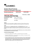
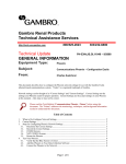
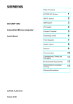
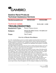
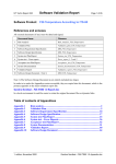
® Gambro Renal Products Technical Assistance Services http://tech.usa-gambro.com 800/525-2623 Technical Update 303/232-6800 PH,TR,11033 – 6/2006 TROUBLESHOOTING Equipment Type: Phoenix Dialysis System Subject: Troubleshooting Boot-Up Problems: “Rx MGMT Key Only” From: Gary Willis PURPOSE: To provide Phoenix service technicians with guidelines for troubleshooting problems related to incomplete or incorrect boot-up. SYMPTOM: After completing boot-up, the IDLE screen has only the Rx MGMT Action Key with the red Alarm Pictogram above it. The Navigation Tabs are unresponsive to touch. Typically, there are no other visual or audible alarms. See Fig. 1 below. CAUSE: The Phoenix has booted-up in a condition where the Carrier (Main) CCA (circuit card assembly) and program are not communicating with one or more of the Slave CCA’s. In this condition, the main program halts (locks-up) and softkeys and keypads become unresponsive. Conditions that can result in these symptoms are: 1. Poorly seated Slave or Carrier CCA - Data bus lines are physically interrupted, preventing data from entering or leaving the Slave or Main CCA data bus. 2. Defective Slave or Carrier CCA - Slave or Carrier CCA is unable to communicate correctly on the data bus. 3. Low 5 volt power supply - Data communication is dependent on 5V pulses. If the 5V power supply voltage falls too low, data can become corrupted or lost causing the main program to generate communication alarms or to halt (lock-up) completely. 4. Defective Power Supply – A faulty alarm signal from the power supply can disable normal communications from the slave and Main CCA’s. 5. Defective Compact Flash – A faulty compact flash, or one with corrupted data files, can interfere with normal communication between slave CCA’s. TROUBLESHOOTING: 1. With the main power OFF, reseat all CCA’s correctly in the card cage and turn the main power ON. 2. If present, check that the +5VB/+5VD Jumper (6977953) is correctly installed. 3. With the main power ON, identify the communication LED’s on each card cage CCA and observe that they are flashing normally. See Fig. 2 below. If necessary, compare the LED’s with another Phoenix machine that is in IDLE and that is functioning normally. Replace any CCA whose communication LED is not flashing correctly. (Note: If the Protective and Carrier CCA are the only boards where the communication LEDs are flashing, measure the voltage at J2-1 (PWFAIL) on the Phoenix motherboard. Normal voltage is TTL High (2.7V-5.0V). If the voltage is TTL Low then only the Protective and Carrier CCA communication LEDs will flash, but at a rate slower than normal. Confirm the same measurement at the power supply by disconnecting power supply connector J6 and measuring pin 1. If the voltage is still TTL Low, then replace the power supply.) 4. Measure and verify that the 5V power supply voltages are within the specifications indicated in Phoenix Service Manual: Maintenance, Section 8 – Calibrations, Power Supply Verifications (4.9V – 5.3V). (Note: If the voltage falls much below 4.95V, random communication errors may begin to be observed.) If the voltage is ≤ 4.95V: a. Verify connectivity of the Phoenix motherboard main power connector (J37). Methods of improving the connection: i. Install J37 Connector Locking Kit to stabilize connection. (P/N 6975114) ii. Apply electrical connection enhancer (Stabilant 22) to connector pins. (P/N 6975186) iii. Install a +5VB/+5VD Jumper (6977953) on machines with a transformer power supply. iv. Replace J37 connector. (P/N 6976336) b. Verify at the J37 connector that the unloaded voltages from the power supply (J37 and J2 disconnected) are relatively close to the voltage specifications in Phoenix Service Manual: Maintenance, Section 8 – Calibrations, Power Supply Verifications. If not, the power supply may need to be replaced. (Note: No specific specifications are provided for unloaded power supply voltages. However, any voltage measurement that is significantly below it’s loaded equivalent should be treated as suspicious.) 5. Replace the Compact Flash and confirm that the Rx MGMT, SETUP, and ADR keys are present after reboot. If only the SETUP key is not present, do an ADR Rinse and confirm that the SETUP key returns. Fig. 1 COMMUNICATION LED’S CCA LED CARRIER DL1 PROTECTIVE SLAVE V9 BLOOD SLAVE V50 HYDRAULIC SLAVE V50 BIOSLAVE (6970362) DL2 BIOSLAVE (6971055) DL5 Fig. 2