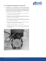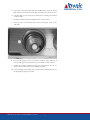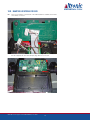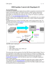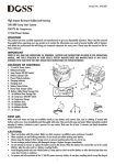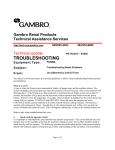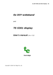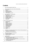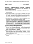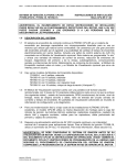
1
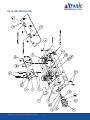
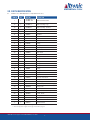
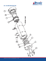
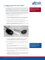
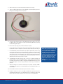
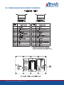
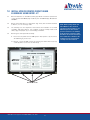
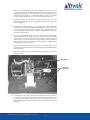
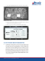
Service Manual
GOV 10/50 Gas Engine Governor
Form GOV SM 3-15
GOV SM 3-15 All rights reserved © ALTRONIC, LLC 2015
GOV10 SERIES
GOV50 SERIES
GOV10EP-10
GOV50EP-10
GOV10EP-10A
GOV50EP-10A
GOV10EP-11
GOV50EP-11
GOV10EP-11A
GOV50EP-11A
GOV10EP-20
GOV10EP-20A
GOV10EP-21
GOV10EP-21A
NOTE: Please refer to Service Bulletin
518 for details to dP transducer
changes and PCB part numbers
required for GOV10 above S/N 2500
and GOV50 above S/N 1200.
IMPORTANT SAFETY NOTICE:
Proper installation, maintenance, repair and operation of this equipment is essential.
The recommended practices contained herein should be followed without deviation.
An improperly installed or operating governor system could cause personal injury to
operators or other nearby personnel.
TABLE OF CONTENTS
SECTIONITEM...................................................................................................... PAGE
1.0
GOV SERVICE AND REPAIR MANUAL OVERVIEW..............................................3
2.0
PARTS IDENTIFICATION.................................................................................5
3.0
CLEANING OR REPLACEMENT OF PILOT FILTER...............................................8
4.0
REMOVAL OF THE POPPET VALVE ASSEMBLY................................................ 10
5.0
REMOVAL OF DEBRIS FROM THE METERING HOUSING....................................11
6.0
REPLACEMENT OF THE PRESSURE TRANSDUCERS........................................11
7.0
INSTALL UPDATED PCB’S USING 881001-KT................................................ 14
8.0
GOV PRESSURE SENSOR TROUBLESHOOTING............................................... 17
9.0
GOV 10/50 FIELD APPLICATIONS................................................................. 18
10.0
BUMPER LOCATIONS FOR GOV..................................................................... 19
GOV SM 3-15 All rights reserved © ALTRONIC, LLC 2015
2
This document comprises a general overview of
the products described herein. It is solely for
informational purposes and does not represent
a warranty or guarantee. Contact Altronic, LLC
for detailed design and engineering information
suitable to your specific application. Altronic,
LLC reserves the right to modify its products
and related product information at any time
without prior notice.
1.0 GOV SERVICE AND REPAIR MANUAL OVERVIEW
The GOV10/50 Gas Engine Governor has been designed to provide reliable operation with a minimum amount of maintenance. To ensure optimum performance,
periodic inspection and cleaning is necessary.
Preventative maintenance issues can be integrated into the current maintenance
schedule of the engine. Most maintenance requires little effort and no downtime
of the GOV valve.
Corrective maintenance is to be done when the GOV Gas Engine Governor begins to
behave erratically. Procedures have been generated to cover most minor issues.
EXTERNAL VISUAL INSPECTION
Inspect the exterior of the Governor for loose connections, frayed wires or major
structural damage.
CLEANING
Exterior cleaning will aid in the visual inspection of the external casing and ensure good connections. Ethyl alcohol or mild soapy water can be used as cleaning agents.
MAINTENANCE LOG
To facilitate troubleshooting and to establish service schedules, a maintenance
log should be kept on the Governor.
CALIBRATION
Flow calibration of the GOV is performed in a controlled environment before shipment. Since calibration of the Governor requires equipment not normally available in the field, it is recommended that the device be returned to the Altronic
distributor serving your area.
PILOT GAS FILTER
The internal pilot gas filter, if installed, should be changed every six (6) months
or more frequently if necessary.
Throughout this service manual, service parts will be identified by the item number assigned in the parts list in section 2.0. For example, (1a) and its position
inside the GOV device can be found by locating that item number on Fig. 1A on
page 4 or 1B on page 6 and identified in section 2.1 or 2.2.
GOV UPDATES:
n In addition to the standard procedures, older GOV10 units below S/N
852 or GOV50 units below S/N 244 will require some items (such as
the pressure transducers) to be changed. These items and procedures
are identified by specific notes (“When Updating Units below S/N 852”)
within the appropriate sections of the manual.
n In addition to the repair of malfunctioning units, instructions are given in
SECTION 7 which describe the process of updating an older GOV to the
current configuration of PCB assembly.
GOV SM 3-15 All rights reserved © ALTRONIC, LLC 2015
3
FIG. 1A PART IDENTIFICATION
GOV SM 3-15 All rights reserved © ALTRONIC, LLC 2015
4
2.0 PARTS IDENTIFICATION
2.1
PARTS LIST - GOV10 (Reference exploded view at left.)
ITEM NO.
QTY
PART NO.
DESCRIPTION
1
1
881001-1KT or
881001-2KT
PCB Field Retrofit Kit
1a
1
872002-1 or
872002-2
PCB Assembly, Logic
1b
1
872003-1
PCB Assembly, Terminal
1c
1
802010-1
Label, Terminal Board
1d
5
610228
Standoff
1e
2
810103
Standoff
1f
1
810105
Standoff
1g
6
902598
Screw 6-32
1h
2
902650
Screw, 6-32
1i
1
510698
O-ring
1j
5
615048
Bumper-Adhesive backed
2
1
820002
Valve Repair Kit
2a
1
816000
Wrench
2b
1
810059
Servo Filter
2c
1
803020
O-ring Lube
2d**
16
810027
O-ring
2e
1
50110039
Plug
2f*
4
810042
O-ring
2g
1
810047
O-ring
2h
1
810050
O-ring
2i
1
810051
O-ring
2j*
2
810052
O-ring
2k
1
810082
O-ring
3
1
820004
Pressure Transducer Kit
3a
3
810109
Pressure Transducer
3b
3
810031
O-ring
3c
3
801005
Snap Ring
3d
1
810115
Spacer (req’d on some housings)
3e
1
803020
O-ring Lube
4
1
820005
dP Transducer Kit
4a
1
50102008
dP Transducer Assembly
4b
4
801049
Screw, 10-32
4c
1
803020
O-ring Lube
5
1
50105008
Regulator Assembly - GOV10
6
12
801084
Bolt, 1/4”-20 x 1.5”
7
1
810128
Flapper Shield
* This item appears in figure 1B on page 6.
** This item appears in figure 1A on page 4 and 1B on page 6.
GOV SM 3-15 All rights reserved © ALTRONIC, LLC 2015
5
FIG. 1B PART IDENTIFICATION
GOV SM 3-15 All rights reserved © ALTRONIC, LLC 2015
6
2.2
PARTS LIST - GOV10
Reference exploded view at left.
ITEM NO.
QUANTITY
PART NO.
DESCRIPTION
2
1
820002
Valve Repair Kit
2a
1
816000
Wrench
2b*
1
810059
Servo Filter
2c
1
803020
O-ring Lube
2d**
16
810027
O-ring
2e*
3
810031
O-ring
2f
4
810042
O-ring
2g*
1
810047
O-ring
2h*
1
810050
O-ring
2i*
1
810051
O-ring
2j
2
810052
O-ring
2k*
1
810082
O-ring
7
1
8
1
9
1
880002
Poppet Valve Assembly
50106079-2
Flange, Inlet (4-bolt flange)
50106039-2
Flange, Inlet (8-bolt flange)
50106079-1
Flange, Outlet (4-bolt flange)
50106039-1
Flange, Outlet (8-bolt flange)
801028
Bolt, 3/8"-16 x 1.75" (4-bolt flange)
801082
Bolt, 3/8"-16 x 0.75" (8-bolt flange)
10
14
11
1
801030
Snap Ring
12
1
50106029
Metering Orifice
* This item appears in figure 1A on page 4.
** This item appears in figure 1A on page 4 and 1B on page 6.
GOV SM 3-15 All rights reserved © ALTRONIC, LLC 2015
7
NOTE: Part numbers for items 7-12
apply to GOV10 series only. Contact
factory for information for the GOV50
series.
3.0 CLEANING OR REPLACEMENT OF PILOT FILTER
3.1
The following section covers the replacement or cleaning of the pilot filter (2b).
Before starting, it is recommended that a clean flat work surface be prepared
and the proper tools be made available. Refer to section 2 for required parts.
It is also recommended that the Valve Repair Kit P/N 820002 (Item 2) be
purchased which contains all of the required items such as a spanner wrench,
replacement O-rings, replacement filter and O-ring lube. See Fig.1A on page 4
for location of parts. See the photo below for details.
A. Using the spanner wrench (2a), apply pressure in a counter-clockwise motion and remove the regulator assembly (5).
B. DO NOT remove the regulator adjustment screw and nut. If these are removed, the correct regulator settings (42 psid) cannot be reset without
returning the Governor for re-calibration.
C. Check to see that the regulator does not interfere with the end flanges. If
there is no interference, continue to step E. If there is interference, the inlet
flanges need to be removed (step D).
D. Using a 5/16" Allen wrench, remove the 7 cap screws (10) holding the inlet
flange (8) to the main body. Remove the flange (8).
E. The filter O-ring (2k) and filter (2b) should now be visible.
F. Carefully remove the O-ring (2k) for later use. Inspect the O-ring for cuts
and abrasions before reuse. If there is any physical damage to the O-ring, it
must be replaced.
GOV SM 3-15 All rights reserved © ALTRONIC, LLC 2015
8
G. If you have a replacement filter (2b) and do NOT want to reuse the current
filter, puncture the filter with a sharp object and remove it. Continue to step J.
H. If the filter (2b) is to be reused, use a dental pick to carefully ease the filter
out by its edges.
I. Backflush the filter (2b) with stoddard solvent or other cleaner.
J. Place the new or cleaned filter (2b) into the housing filter cavity, coarse
side down.
K. Place the O-ring (2k) in front of the filter to fasten it. When replacing or
reusing an O-ring, the proper lubricant (2c) should be used at all times.
L. Tighten the regulator assembly (5) using the spanner wrench (2a) in conjunction with a torque wrench set for 30 lb-ft of torque.
M. If the end flange was removed, place a small amount of O-ring lube (2c) on
the flange O-ring (2j) and re-install.
GOV SM 3-15 All rights reserved © ALTRONIC, LLC 2015
9
4.0 REMOVAL OF THE POPPET VALVE ASSEMBLY
refer to fig. 1b on page 6
4.1
The following will cover the removal of the poppet valve assembly (7) from the
GOV10 Gas Engine Governor. The poppet valve assembly should not be removed
from the GOV50. Since the GOV10 center section is not serviceable in the field,
a replacement assembly must be installed if on-site repairs are desired. If the
poppet valve assembly (7) is removed for inspection or replacement, the O-rings
(2f) may be damaged. The required O-rings (2f) are included in the Valve Repair
Kit (2). The replacement poppet valve assembly (7) is sold separately. For the
GOV50 only, contact the factory with the model number and serial number of
the GOV50 if the poppet valve assembly requires service.
WARNING: Use eye protection as the
snap ring can release out of the assembly unexpectedly.
A. Remove the GOV10 valve from the fuel line.
B. Remove the outlet flange (9), being careful not to cut the flange O-ring (2j).
If needed, tap the flange upward with a rubber mallet to ease removal.
C. Using a pair of snap ring pliers, remove the steel snap ring (11). D. Using the soft, rubber coated side of the snap ring pliers, pry out the orifice
metering plate (12). Do not damage the inner edge in any way.
E. Remove the inlet flange (8) being careful not to cut the O-ring (2j). Again,
tap the flange with a rubber hammer to ease removal.
F. Put a 2" diameter PVC pipe over the downstream portion of the center section. Using a rubber mallet, tap the PVC pipe until the center section is
removed from the housing. Do not press or turn the poppet itself.
G. Coat the three O-rings (2f) of the new center section with O-ring lubricant (2c).
H. Insert the poppet assembly (7) into the valve body with the cone facing in
the upstream direction.
I. Align the control pressure inlet of the poppet assembly with the dowel insert
of the control pressure transducer. J. Click the center section in place by providing sufficient downward force on
the center section cone. In the field, this can be done by CAREFULLY standing on the cone portion of the center section when it is oriented vertically.
K. Replace the inlet flange (8) - it has two ridges. Tighten down the 7 cap
screws (10) to 6 lb-ft torque each.
L. Apply O-ring lubricant (2c) to the orifice O-ring (2f). Firmly press the orifice
plate (12) into the valve body at the outlet end. Ensure that the taper faces
the downstream side of the Governor valve.
GOV SM 3-15 All rights reserved © ALTRONIC, LLC 2015
10
NOTE: The cone of the assembly,
which does not have a cap screw,
lines up with the control pressure
inlet of the assembly.
M. Replace the snap ring (11).
N. Replace the outlet flange (9). Tighten down the 7 cap screws (10) to 6 lb-ft
torque each.
O. Return the malfunctioning poppet valve assembly (7) to Altronic for repair.
5.0 REMOVAL OF DEBRIS FROM THE METERING HOUSING
5.1
Occasionally some form of foreign debris will get into the metering housing and
become lodged inside. This will cause the GOV to malfunction in such ways as
failure to shut-off (leakage) and incorrect transducer readings affecting governor
accuracy. Any debris should be removed by using compressed air.
A. Upon the removal of the poppet assembly (7) from the metering housing of
the GOV, inspect the housing for any internal damage that may have occurred.
B. Shop air can be used to blow away and clean any loose particles that may
have accumulated. DO NOT use any hard-edged instrument to clean the
valve housing.
C. Holding the center section in hand, apply instrument air to the poppet assembly through the control pressure port (PC).
D. The poppet valve will open with 30 to 70 psi air applied. Do not exceed
this range.
E. Using a soft edged device (i.e. popsicle stick, Q-Tip, etc), hold open the
poppet valve. Do NOT use any hard-edged instruments (i.e. screwdrivers)
as this will damage the assembly.
F. Ensuring that the poppet assembly is clear of debris, release the poppet valve.
G. Re-lubricate the O-ring seals (2f) of the poppet assembly (7) and reinstall
as instructed.
6.0 REPLACEMENT OF THE PRESSURE TRANSDUCERS
6.1
Replacement of the three single point GOV pressure transducers (3a) can be
performed in the field under the direction of the distributor or Altronic personnel. The three transducers (3a) are identical. One transducer kit (3) contains all
necessary parts to change one transducer; if changing all three, three kits are
required. The three transducers are identified on Fig. 2 on page 13 as:
n Control pressure transducer - Ref. point P3 on Fig. 2
n Outlet pressure transducer - Ref. point P4 on Fig. 2
n Supply pressure transducer - Ref. point P2 on Fig. 2
By replacing a transducer (3a) in the field, accuracy of the GOV FLOW measurement may be slightly affected due to the small variances in the transducers. To
replace a transducer (3a), use the following procedure (refer to fig. 1a on page 4):
A. Remove the electronics housing cover by removing 12 bolts (6).
B. Examine and make notes of the GOV electronic board assembly (1a) which
show the wire routing and orientations.
C. Unclip the affected transducer (3a) from the electronics board (1a) and
unscrew the board (1a) from the circuitry housing. Do not remove more
wires than necessary.
D. Using snap ring pliers, remove the snap ring (3c) of the affected transducer (3a).
GOV SM 3-15 All rights reserved © ALTRONIC, LLC 2015
11
CAUTION: Due to the strong nature of
the shutoff spring within the center
section, DO NOT place your fingers
near the poppet valve if it is in an
open position.
E. With a small pry tool, remove the transducer (3a) from its housing.
F. There is an O-ring (3b) placed on the underside of the transducer (3a). If this
O-ring (3b) is damaged, it must be replaced.
G. Insert the new transducer (3a) into the appropriate position, taking care to have
the O-ring (3b) in place within the cavity. Use the O-ring lubricant (3e) to help
hold the O-ring (3b) in place.
H. Re-insert the snap ring (3c) to hold the transducer in place.
I. Using a paper clip to hold open the spring clip, insert the three wires coming from
the pressure sensor into the plastic connector in proper order as shown in Fig. 2.
J. If the differential pressure transducer (4a) requires replacement, remove it by
removing the four mounting screws (4b). After the screws are removed the differential pressure transducer (4a) can be lifted straight up from the control housing.
There are two small connecting tubes in the control housing when replacing the
transducer (4a); be sure to carefully align these before pressing down on the new
differential pressure transducer (4a) to install it.
K. The differential pressure transducer (4a) connects to the PCB assembly (1a)
through a plastic connector as detailed in Fig. 2. Using a paper clip to hold open
the spring clip, insert the four wires coming from the differential pressure sensor
(4a) into the plastic connector in proper order as shown in Fig. 2 for Reference
point P6.
L. Attach the wiring to the electronics board (1a) in the proper orientation. NOTE:
The red wire of the harness is on the downstream side of the Governor valve - see
the flow label.
M. Re-assemble the electronics board (1a) to the electronics housing.
N. Install the electronics cover to the GOV. Do NOT allow any wires to become
pinched when replacing the cover. Re-tighten the cap screws (6) to 40 in.-lb.
torque. Maximum clearance between the cover and the housing is 0.0015".
GOV SM 3-15 All rights reserved © ALTRONIC, LLC 2015
12
NOTE: When updating GOV units with
a serial number below S/N 852, the
use of a spacer (3d) is required to
hold the transducer in place with
snap ring (3c). Spacer (3d) is installed on top of the transducer (3a)
prior to the installation of the snap
ring (3c) to effectively raise the
height of the transducer to match
the height of the older transducer
housing.
FIG. 2 WIRING DIAGRAM FOR REPLACEMENT TRANSDUCERS
GOV SM 3-15 All rights reserved © ALTRONIC, LLC 2015
13
7.0 INSTALL UPDATED PRINTED CIRCUIT BOARD
ASSEMBLIES USING 881001- KT
7.1
Retrofit installation of new PCB assembly (1a) MUST include the replacement
of the obsolete TCA-100 display module by the new GOV Display Module P/N
891002-1.
7.2
Retain all removed parts in a small plastic bag. These parts should be returned
to Altronic, Inc. for exchange credit.
7.3
The following tools are required for the removal and installation of the PCB
assembly: 3/16" Allen wrench, 1/4" nut driver or wrench, Phillips head screw
driver, large sized paper clip, a screw holding screwdriver.
7.4
Removing the older style PCB assembly.
A. Disconnect the power from the GOV system. After power is off, disconnect
all field wiring at junction box.
B. Remove cover from GOV housing by removing the twelve Allen head cap
screws (6) which secure it to the main body.
Allen Head Screws
GOV SM 3-15 All rights reserved © ALTRONIC, LLC 2015
14
NOTE: When updating GOV10 units
with S/N 852 or lower, the three
obsolete pressure transducers (3a)
MUST be replaced. The obsolete
pressure transducers are identified
by the presence of four wires rather
than three. The obsolete transducers
have a white wire in addition to the
normal black, red and green wires
currently used. See Section 5.
C. Remove the old PCB assembly by removing the six Phillips head screws
which secure it to the control housing base. With the PCB assembly
loose, unplug the four 12-position terminal plugs from the underside of
the old PCB assembly.
Mounting Screws
D. Locate the three wires connecting the PCB assembly to the old power
supply assembly colored solid orange, solid purple and solid blue. Remove these wires from the terminal plug they connect to. To remove
these wires, insert a large sized paper clip into the hole above each wire.
Slip these three wires out of the tied wire bundles. These wires will not
be used with the new PCB assembly.
Terminal Plugs
Standoffs
Long Standoff
Power Supply
Field Wiring
GOV SM 3-15 All rights reserved © ALTRONIC, LLC 2015
15
E. Remove the two standoffs next to the power supply. Remove the four small cap
screws which hold the power supply to the valve housing. At this point, the power
supply PCB and field wiring can be removed from the unit. To remove these items,
pull the wiring back through the conduit opening. Bag these parts. The remaining
two terminal plugs will be used to connect to the new PCB assembly (1a).
F. Remove the remaining four standoffs and bag these parts. All of the standoffs will be replaced by new parts supplied with the PCB replacement kit,
P/N 881001-KT (1).
G. To install the new PCB assembly (1a), replace the older standoffs which were
removed with the new standoffs supplied in 881001-KT (1) . These standoffs are
not the same length as the older parts. Install the 1.25" length standoff (1f) from
the kit where shown. Install five of the short 0.25" length standoffs (1d) into the
remaining standoff locations.
H. Place the terminal PCB assembly (1b) into the cavity where the power supply
was removed with the ribbon cable oriented as shown. Secure the terminal PCB
assembly (1b) to the unit as shown with the two medium length standoffs (1e)
which are 1.215" long. The male end of these standoffs goes through the terminal
PCB (1b) and screws into the two smaller standoffs (1d) in the cavity where the
old power supply board was removed.
I. Reconnect the field wiring from the junction box to the terminal strip on the terminal PCB assembly (1b). See the attached wiring table and the GOV Operating
Manual for details.
J. After wiring is verified, secure the terminal board label (1c) with the screws (1h)
provided in the kit.
Field Wiring
New PCB
Configuration
K. Insert the ribbon cable connector from the terminal board (1b) into the header on
the bottom of the new logic board (1a). Plug the two remaining original 12-position plugs into the corresponding headers on the new logic board (1a). These
plugs and headers are keyed and will only fit together properly with their assigned
mating part.
GOV SM 3-15 All rights reserved © ALTRONIC, LLC 2015
16
L. Dress the wires appropriately, taking care to not stress any connections or wires.
GOV with new PCB assembly
M. Mount the new logic PCB assembly (1a) to the standoffs using the screws (1g)
provided in the kit. Install and tighten all six screws.
N. Replace cover and secure with the original twelve Allen head screws (6).
8.0 GOV PRESSURE SENSOR TROUBLESHOOTING
8.1
The FMP, FSP, and FCP transducers are all the same part number and are
interchangeable. If a transducer is suspected to be bad, the transducer output
voltage can be measured with a digital voltmeter. The RED and BLACK wires
are a 10vdc power source, and the GREEN wire is the sensor output (sensor
output voltage is measured on GREEN + with respect to BLACK -). The transducer output is 0 - 2.5 volts from 0 to 260psi. Since this is an absolute pressure
transducer, it is normal for the unit to have a positive voltage output at 0psig
(typically 0.10 - 0.15Vdc). Fig. 2 on page 13 shows a pinout for the connectors
for use in measuring and verifying the stability of these voltages. Be sure to zero
the transducers using the display menu under Sensor Configuration, as well as
using the AutoZero function when V2.0 firmware is being used. Please refer to
section 16.0 of the GOV Operating Manual, FORM GOV OM 04-06 for details
on AutoZero (AZ) functions.
GOV SM 3-15 All rights reserved © ALTRONIC, LLC 2015
17
9.0 GOV-10/50 FIELD APPLICATIONS
9.1
GOV10/50 Gas Engine Governors have proven their reliability and service on
Cooper, Clark, Ingersoll-Rand, and other integral compressor engines. In recent
years, many GOVs have been applied to a number of fuel-admitted engines in
field compression applications, including a number of Superior models. These
latter applications are more difficult because they are often subject to higher
vibration and temperatures levels, as well as liquids and corrosives resident in
the fuel gas. Operational problems encountered are sometimes seen as a pressure sensor offset or error (fuel supply, control, or manifold pressure). In areas
of vibration, and the normal outdoor environment which is vented into the unit
(the control housing has a flameproof vent to atmosphere and is certified for
explosion-proof enclosures), a condition known as “thin film resistance” can
occur on the pins of the plug in the PCB connector. This resistance acts as an
insulator to the low voltage and low current sensor signals and is seen in operation as an error in the reported pressure. To improve the operation of these
connections, a liquid solution known as Stabilant 22 has made a remarkable
improvement where these issues have been reported. Stabilant 22 has been
used in the aerospace, automotive, and computer industry for many years, and
has been used on many sensor applications similar to those used in the GOV.
Typically this product is used as Stabilant 22A, which is 4/5 isopropyl alcohol,
allowing it to penetrate the connector and evaporate, leaving behind the connection enhancer. Any GOV which exhibits these issues can be easily improved
by applying this product to these connectors. For more information on Stabilant
22 go to www.stabilant.com. This product can be purchased in a 15mL bottle
(enough for hundreds of connectors) by ordering it at your local NAPA or auto
parts store that sells Standard Motor Products (Niehoff). The NAPA-Echlin part
number is CE 1, and the Standard Motor Products part number is SL 5. Both
retail for about $60. This product may have other applications where intermittent connectors have caused havoc in control and sensor systems.
GOV SM 3-15 All rights reserved © ALTRONIC, LLC 2015
18
10.0 BUMPER LOCATIONS FOR GOV
10.1 There is one bumper on the bottom of the PCB. Stabilant is added to both halves
of the white connectors.
There are four bumpers inside the lid. Two of these align with the connectors. If
the lid is flipped, the other two bumpers align with the connectors.
GOV SM 3-15 All rights reserved © ALTRONIC, LLC 2015
19