1
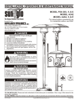
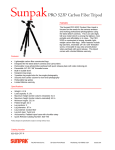
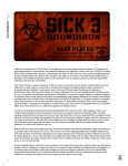
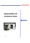
Infrared Dynamics
FOR YOUR SAFETY:
If you smell gas:
1. Open windows.
2. DO NOT try to light any appliance
3. DO NOT use electrical switches
4. DO NOT use any telephone in your
building
5. Leave the building
6. Immediately call your local gas
supplier after leaving the building.
Follow the gas supplier’s
instructions.
7. If you cannot reach your gas
supplier, call the Fire Department
SUNPAK
®
Gas-Fired, Unvented
High-Intensity
Infrared Heaters
For use Indoor/Outdoor Commercial
Outdoor Residential ONLY
Installation, Operation
& Maintenance Manual
WARNING
Fire Hazard
Do not store or use gasoline or other
flammable vapors and liquids in the vicinity
of this or any appliance.
Failure to follow these instructions can result
in death, injury or property damage.
Model S25
Model S34
WARNING
Fire and Explosion
Improper installation, adjustment, alteration,
service or maintenance can result in death,
injury or property damage. Read the
installation, operation and service manual
thoroughly before installing or servicing this
equipment.
Installation and replacement of gas piping,
gas utilization equipment, or accessories,
and repair and servicing of equipment shall
be performed by a qualified agency familiar
will all precautions required regarding this
type of equipment and that has complied
with all requirements of the authority having
jurisdiction.
Installer
Please take the time to read and understand these
instructions prior to any installation. Installer must be
given a copy of this manual to the owner.
Owner
Keep this manual in a safe place in order to provide
your serviceman with the necessary information.
Infrared Dynamics, Inc.
3830 Prospect Avenue
Yorba Linda, CA 92886
Telephone: (714) 572-4050
Fax: (714) 572-6093
Toll Free: (888) 317-5255
www.sunpak.us
© Copyright 2011 Infrared Dynamics, Inc
Printed in the U.S.A.
P/N 65132-7/11
Sunpak® Infrared Heaters
Starting Your Heater
Table of Contents
1.
2.
3.
4.
5.
6.
Turn gas and 24 VAC electrical power “ON”. The pilot and
burner should light within 4 seconds. A flame sensor will
shut off the spark. If the burner does not light within 15
seconds the flame sensor will shut “OFF” the gas valve. To
relight the pilot and burner, shut “OFF” power. Wait 5
minutes. Turn power back “ON”.
Owner’s Manual
Design Guide
Installation / Service Instructions
Replacement Parts
Trouble Shooting Guide
Warranty
If the heater will not light, turn the manual gas valve to
“OFF” position and the electrical switch “OFF” to the heater
and call your quality service agency or gas supplier.
Shutting Down Your Heater
WARNING
Turn electrical power to the heater “OFF” .
Should you need to shut down your heater for service or
maintenance, the manual gas valve next to the heater
should also be turned “OFF”.
Prop. 65 - Carbon Monoxide
If not installed, operated and maintained in
accordance with manufacturer’s instructions,
this product could expose you to substances in
the fuel or from combustion, including Carbon
Monoxide, which can cause death or serious
illness and which are known to the State of
California to cause cancer, birth defects or
reproductive harm.
Performing Routine Maintenance
Overtime, particularly during long periods of disuse, the
heater can accumulate dirt and debris in and around the
pilot and the burner. Routine maintenance should be
performed at least once a year by a qualified service
agency to insure the heater is operating properly. More
frequent service may be required for heaters located near
waterfronts.
Stainless Steel Heater
Owner’s Manual
Stainless steel does not “rust”; however air pollution can
leave brown deposits on heaters. We recommend washing
the outer stainless steel casing only with a mild detergent
solution and wiping it dry with a soft cloth to bring back the
original shine. The stainless steel may be expected to
permanently darken around the top of the heater over time
with extended use.
Before Starting Your Heater
Before you start your heater examine the heater
installation to determine that:
• Areas immediately around the heater including the
air inlet and flue areas are free from obstructions.
• Physical support of the heater is sound.
• There is no obvious deterioration of the heater.
Before You Remodel
Should you plan to make any changes to the patio or
building structure after heaters have been installed, your
heater installation must be reviewed by a qualified agency
to insure that clearances from combustion material and
ventilation requirements are maintained after alterations are
complete. When plastic curtains or drops are used to
enclose a patio you must take steps to insure that Sunpak
heaters have the required permanent access to outside air.
If a patio is to be partially enclosed a qualified agency
familiar with this type of heating equipment must be
consulted to insure the safe operation of this equipment.
Starting and Shutting Down Your Heater
Sunpak utilizes an automatic ignition system. Follow
these important safeguards.
• Never attempt to manually light the burner with a
match or other source of flame.
• Read and follow the operating instructions on the
inside of heater door especially the item that reads
as follows:
Wait 5 minutes to clear out any gas. Then smell for
gas. If you smell gas follow the instructions on the
front of this manual regarding gas leaks. If you don’t
smell gas, go to the next step.
• If a suspected malfunction occurs with your gas
control system, such as the burner does not light
when it should, refer to the section ‘Shutting Down
Your Heater’.
2
Sunpak® Infrared Heaters
Heater Layout and Design
Sunpak® heaters were specifically designed to provide
heated comfort in an outdoor environment. They have
been used on outdoor patios across the United States and
Canada for over 20 years. When properly integrated into a
patio design, Sunpak® heaters generally increase the
comfort level 5 to 10 degrees Fahrenheit outdoors. The
heating effectiveness will depend on air temperature, wind
velocity and other factors. Whenever possible local
Sunpak® installations should be reviewed to determine the
effectiveness for regional environments.
The environments in which Sunpak® heaters are
utilized vary greatly. As an outdoor rated heater it has
passed basic wind and rain tests. This does not mean the
heater cannot be damaged by the environment or when
operated in very windy conditions. For this reason it is
strongly suggested that heaters be inspected and if
necessary repaired annually or before each heating
season.
The variable environments in which Sunpak® heaters
are applied means that these general guidelines are
general by necessity and may need to be refined for local
conditions. These guidelines are to be used in
combination with the installation instructions.
Breezy conditions must be considered when heating any
patio. Windbreaks can be extremely effective in increasing
comfort and reducing heating costs. Windbreaks must be
designed in such a way to allow for the necessary fresh air
and ventilation for proper heater operation (see ventilation
of installation section).
WARNING
Asphyxia / Carbon Monoxide
Heater requires adequate combustion air and
ventilation in order to operate safely. Improper
ventilation can generate carbon monoxide or
other harmful gases that could result in death
or breathing difficulties. Small or enclosed
patios may not be appropriate to for this type
of heater.
Sunpak heaters must always be operated in a location
that allows uniform air pressure around the heater. If only
part of the heater is located in a wind protected zone
damage to the heater may occur. Time should be taken to
observe how the wind will affect the heaters under local
conditions.
Caution
Patio Design Consideration
Heater placement is critical for effective and efficient
patio heating. If heaters are placed too close together or
mounted too low, people become uncomfortable. If
heaters are placed too far apart on a breezy, wind-swept
patio the patio may never get warm.
Sunpak® heaters work best if they are placed in areas
of the greatest heat loss, such as the open side of a semiprotected patio area. The Sunpak® heater may be
mounted at up to a 30 degree angle or face down. Note
that the top clearances required from combustible material
increases when heaters are at any angle. The heater must
always be horizontal to the floor.
WARNING
Fire and Explosion
Proper clearance for combustible materials must be
maintained. See installation section of this manual
for required clearances for different model and
mounting options.
Sunpak heaters may be laid out in a number of
configurations depending on the structural constraints of
the patio and heating requirements. One approach is to
face heaters straight down over the table and seating
areas. Another approach is to locate heaters to the side
and to angle them inward. A third approach is to cluster
the heaters in the center of the patio and angle heaters
outward. It all depends on the needs of a particular patio.
Damage to Heater
Failure to operate heater in a uniform air
pressurize environment or under erratic wind
conditions can cause over-heating of controls,
and damage to the front grill and burner.
Temperature Control
A thermostat can be incorporated into the electrical
circuit; however this may not be the best means of
temperature control. Because the infrared heat warms
people and objects, when used outdoors the heater may
not increase the air temperature and thus the thermostat is
never satisfied.
When multiple heaters are used it is suggested that they
be put on individual switches to provide flexibility in
heating. Typically all the heaters would be turned on to
heat a cold patio, and then heaters would be turned off
selectively as people settle in. A timer or master switch
may be convenient to ensure the heaters are not turned on
when the patio is not in use.
3
Sunpak® Infrared Heaters
CEILING
MINIMUM CLEARANCE FROM COMBUSTIBLE MUST BE MAINTAINED (see chart opposite page)
SUNPAK will raise the comfort level 5-10º Fahrenheit
outdoors. The above coverage table was based on
still breeze conditions. Under windy conditions more
heat will be required. It is recommended that a
windswept patio be designed with wind breaks to
stabilize the patio environment. Wind breaks shall
NOT interfere with the ventilation of combustion air
requirement of the heater(s).
4
ANGLE MOUNTING: Most models of the SUNPAK
heater may be angle-mounted to a maximum of 30º
to accommodate mounting the heaters around the
edges of the patio. Note that the top clearance to
combustibles increase when heater is tipped from
the horizontal.
NOTE: Local codes may have special requirement
regarding head clearance requirements. Some local
codes require all portions of overhead radiant
heaters to be located at least 8 foot above the floor.
Sunpak® Infrared Heaters
5
Sunpak® Infrared Heaters
Gas Supply
Installation/Service Instruction
The gas inlet supply pressure and manifold pressure
required for each heater are listed below. For gas supply
line pressures in excess of ½ psig, consult with your
representative or the factory.
Receiving Equipment
On receipt of equipment it is suggested that a visual
inspection be made for external damage to the carton. If the
carton is damaged, a note should be made on the Bill of
Lading when signing for the equipment. Remove the heater
from the carton. If there is damage, report the damage to
the carrier immediately.
Gas Inlet Pressure
Maximum Pressure
Minimum Pressure
Manifold Pressure
Nat Gas
½ psig
6” W.C.
5” W.C.
Propane
½ psig
11” W.C.
10” W.C.
INSTALLATION INSTRUCTIONS
It is important that the gas piping system be adequately
sized for all the gas appliances it serves.
Important Notice
Clearances
These instructions are intended for qualified personnel,
specifically trained and experienced in the installation of
this type of equipment and related system components.
Some states or provinces require installation and service
personnel to be licensed. If your state or province is such,
be sure your contractor bears the appropriate license.
Persons not qualified shall not attempt to fix this equipment
nor attempt repairs according to these instructions.
Each heater must be installed such that the following
“Minimum Clearance to Combustible Materials’ are
maintained.
Combustible materials include wood, compressed paper,
plant fibers, and plastic, Plexiglas or other materials
capable of being ignited and burned. Such materials shall
be considered combustible even though flame-proofed, fire
retardant treated or plastered. Additional clearance may be
required for glass, painted surfaces, vinyl siding or other
materials which may be damaged by radiant or convection
heat.
Adequate space around each heater is required even
when the materials surrounding the heater are noncombustible to provide adequate combustion air and
ventilation of exhaust gases. Heaters should never be
located in a ceiling recess or soffit.
The stated clearance to combustible materials represents
a surface temperature of 90ºF (32ºC) above room
temperature. Building materials with a low heat tolerance
(such as plastic, vinyl siding, canvas, tri-ply, etc.) may be
subject to degradation at lower temperatures. It is the
installer’s responsibility to assure that adjacent materials
are not subject to degradation.
In locations used for storage of combustible materials,
signs shall be posted to specify the maximum permissible
stacking height to maintain required clearances from the
heater to combustible materials.
WARNING
Asphyxia, Explosion or Fire
Improper installation, adjustment, alteration,
service or maintenance may create a hazard
resulting in asphyxiation, explosion or fire, or
damage to the equipment.
Code Requirements
Installation must be in accordance with local codes, or in
the absence of local codes, with the latest edition of the
National Fuel Gas Code, ANSI Z224 and National Electrical
Code ANSI/NFPA 70, and for Canada, the latest edition of
CAN/CGA-B149.1 and B149.2 and Canadian Electrical
Code, CSA C22.1 Part 1 and Part 2.
• Heaters to be installed in Aircraft hangars must be
installed in accordance with American National
Standards for Aircraft Hangars, ANSI/NFPA
No. 409.
• Heaters to be installed in Public Garages must be
installed in accordance with NFPA No. 88A,
Standards for Parking Structures.
• Heaters must be installed so that minimum
clearances marked on the heaters will be
maintained from vehicles parked below the heater.
• Each heater must be electrically grounded in
accordance with the National Electrical Code,
ANSI/NFPA 70, when an external electrical source
is utilized. In Canada, the CSA Canadian Electrical
Code, C22.1 Part 1 applies.
OPTIONAL MOUNTING KIT (#12006): Optional Mounting
Kit is available from your heater supplier. Whether the
mounting kit is used or not, minimum clearance from
combustibles must be observed as follows:
WARNING: The clearances shown below are also
applicable to vehicles parked below heaters.
Model
S25
S34
*S25
S34
Input
BTUH
25,000
34,000
25,000
34,000
Side
In
24”
24”
24”
24”
Rear
In
12”
17”
8”
8”
Ceiling
In
9”
13”
14”
18”
Below
In
48”
48”
48”
48”
Mtg.
Angle
HORIZ
HORIZ
30º MAX
30º MAX
Above clearance apply to models on either natural or LP gas.
*Model S25 for LP gas for use in horizontal position only
.
6
Sunpak® Infrared Heaters
7
Sunpak® Infrared Heaters
Fire Sprinklers
Fire Sprinklers must be located at an appropriate
distance from each heater to avoid accidental
activation of the sprinkler. Ethylene glycol or
propylene glycol must never be used in fire sprinkler
systems where heaters are present as these
substances may become flammable when heated. A
fire sprinkler professional must be consulted when
heaters are installed where fire sprinklers are
present to insure that heaters and the fire sprinkler
system are properly integrated. Specific guidelines
can be found in NFPA 13 regarding design and
specifications for Fire Sprinkler Systems near
heaters.
CAUTION
Sharp Edges
Every effort has been made to remove sharp
edges from this heater; however care should
be taken to avoid injury when reaching inside
the heater during installation and when
servicing this unit.
Electrical
1. Provide only 24 VAC with a NEC Class 2 transformer to
the heaters. Each heater requires approximately 20VA
or 0.8 amps. When multiple heaters are connected to
one transformer, the transformer must be sized to
accommodate the entire load. A transformer must
NEVER be located inside the heater control
compartment.
2. Control wire used to electrically connect one or more
heaters together must have adequate capacity and
insulation temperature rating for the total connected
load. Use at least 18 GA wire up to 50 feet from heater
to transformer or wall switch. Use a minimum of 16 GA
wire for over 50 feet distance.
3. If any of the original wire supplied with the appliance
must be replaced, it must be replaced with wiring
material having a temperature rating of at least 105
degrees Centigrade.
WARNING
Suspension Hazard
Mounting kits and hanging supports must
be able to withstand a minimum working
load of 75 lbs (33 kg). Failure of the
supports can result in death.
Local codes regarding head clearance
requirement must be observed.
Heater Mounting and Support
Heaters shall be mounted in a fixed position
independent of gas and electrical supply line.
Hangers and brackets shall be of noncombustible
material.
Heaters subject to vibration shall be provided with
vibration isolating hangers.
Suitable materials for hanging infrared heaters are
steel pipe, steel channel, or fabricated hangers of at
least 16-gage material. Hanger and brackets must
be secured with adequate anchor to a secure
structure using good building practices. Additional
bracing to protect against seismic forces may be
required in seismically active areas.
WARNING
Electrical Shock Hazard
Disconnect electrical power and gas supply before
servicing
This heater must be connected to a properly
grounded electrical source.
Failure to follow these instructions can result in
death or electrical shock.
8
Sunpak® Infrared Heaters
Ventilation
1.
2.
3.
It is required that areas above the heater be
properly vented to allow for necessary
combustion air and removal of combustion
gases.
Heaters shall be provided with natural or
mechanical means to supply and exhaust at
least 4 cfm per 1,000 BTU per hour of heater
input. Exhaust opening for removing the flue
products shall be above the level of the heaters.
Heater ventilation must comply with state and
local codes.
Gas Piping
1.
2.
3.
4.
5.
6.
7.
A minimum pipe size of ½” is required for inlet
piping. A ½” leaver handled shut-off gas cock
should be installed within 6 feet of the appliance
for servicing the unit.
Check with local and state plumbing and heating
codes regarding sizing of gas lines.
All gas pipe connections to the heater(s) must be
sealed with a gas pipe compound resistant to
liquefied petroleum gases.
Installation of a drip leg in the gas supply line
going to each heater is required to minimize the
possibility of any loose scale or dirt within the gas
supply line from entering the heater’s control
system.
When checking for gas leaks, do not use an
open flame. Use a soap and water solution.
For gas supply line pressures in excess of ½
psig, consult the factory or your local
representative.
Installation of 1/8” N.P.T. plugged tapping
accessible for test gage connections is required
upstream of the gas supply connections to the
heater.
Initial Start-Up Procedure
1. Before turning on the manual gas valve to the heater
verify that the control system is working properly.
a. Apply 24 VAC to the heater.
b. There should be an audible click and the spark
initiates at the pilot
c. With the gas turned off the heater should turn “OFF”
or lockout in within 10 seconds (MICRO 50 controls
will cycle “ON” and “OFF” 3 times before lockout
d. Turn electrical switch “OFF”
2. Turn “ON” the manual gas valve to the heater.
a. Check for leaks using soapy water at all gas
connections and joints. NEVER use a flame to
check for leaks.
b. Apply 24 VAC to heater
c. Check for pilot ignition. A smooth flame front should
roll down the length of the infrared burner. Flame
should stabilize on the ceramic surface.
d. The ceramics portion of the infrared burner should
turn RED within 5 minutes (this may be difficult to
see in bright sunlight).
NOTE: Some white smoke may appear
during or just after the initial start-up of
the heater. White smoke will dissipate
with proceeding use.
9
Sunpak® Infrared Heaters
Servicing Instructions
Turn off gas and electrical before attempting any service
to this appliance. Heater may be serviced by opening the
door to control compartment. Rotate round disk on
control door 90 degrees to open. Top of heater may be
removed for servicing by removing six (6) screws holding
top in place. The top should be removed if the gas
controls, burner or burner orifice is to be replaced.
1. Removal of Burner
a. Remove grille by removing two (2) screws at one
end of the grill near control door. Pull downward
at the end and grill will be loose. The end of the
grill is supported by two (2) pins that enter two (2)
holes in the reflector’s far end.
b. Remove top of heater by removing six (6) screws
holding top in place.
c. The burner can be removed without removing the
pilot-electrode assembly. However, extreme care
should be taken to prevent the burner from
contacting the fragile electrode when removing or
reinstalling the burner. To remove the pilotelectrode assembly, disconnect the orange wire
from the module connected to the electrode.
Detach the pilot tubing. Remove the two screws
holding the pilot-electrode in place.
d. Remove burner clip securing mixer inside control
compartment. Be careful not to damage white
insulation pads.
e. Remove 3/8” hex locknut located inside the
burner orifice bracket holding piping assembly to
burner. A 7/8” 12-point wrench is recommended
to loosen the 3/8” locknut.
f. Remove two (2) screws holding the end of the
burner. Carefully slide burner down and out.
When reinstalling, be sure both ends of the
burner are beneath the reflector end flanges.
g. To reinstall burner, reverse procedure.
2. Removal of RAM-3 Direct Spark Ignition Control
a. Disconnect two 24 VAC power leads
b. Disconnect two gas valve leads.
c. Disconnect igniter lead from control
d. Disconnect green ground lead from casing.
e. Remove two (2) 8-32 x 1 1/4 screws and nuts
holding control module in place. Screw heads are
located on exterior front side of heater above
control compartment door.
f. If insufficient removal clearance, loosen control
assembly and move out of way.
Trouble Shooting
10
1. If no spark from electrode; or if gas valve doesn’t
work then:
a. Check power supply. There should be 24
VAC between the low voltage power wires.
Use voltmeter between inlet 24 VAC wire and
ground terminal at the electrode plate to
measure 24 VAC.
b. Check continuity. Use ohmmeter. For
example, check resistance between valve
wire and ground. Should show almost no
resistance (O ohms) through valve. If high
resistance, check wire connectors.
c. Check spark gap. Spark gap should be 7/64”
(.109”) between electrode tip, and pilot hood.
If gap is too large, spark will occur at wrong
location. If gap is too small it may not be hot
enough to light pilot burner.
d. Be sure connectors are fully inserted into
ignition control (See Wiring Diagram on
rating plate).
2. If insufficient gas flow then:
a. Manual gas valve not full “ON”. Turn valve
handle to full “ON” position.
b. Burner orifice plugged. Remove heater top,
remove burner orifice (use ½” hex wrench)
and thoroughly clean. Spiders often crawl
into orifice hole and make a web, blocking
the orifice.
Sunpak® Infrared Heaters
11
Sunpak® Infrared Heaters
12
Sunpak® Infrared Heaters
13
Sunpak® Infrared Heaters
14
Sunpak® Infrared Heaters
Trouble Shooting Guide
Problem
Possible Causes
No Spark to Pilot
•
•
•
•
•
•
Voltage under 24 VAC
Bad Fuse (Ram-3 Module Only)
Improper spark gap (7/64” or .019”)
Loose ground wire
Broken Electrode
Faulty Ignition Module
Burner Won’t Light
•
•
•
•
Air in gas line
Low gas pressure
Bad Gas Valve
Manual Gas Valve turned “OFF”
Inconsistent Operation
•
Variable gas pressure
(improperly sized gas line)
Variable Voltage
Wind exceeding 10 mph
Tip angle exceeding 30 degrees
Debris inside burner
Erratic winds
•
•
•
•
•
Deterioration of Front Grill
•
Sunpak heater must be installed in such a manner
as to allow the products of combustion or hot
gases to vent out the top of the heater. When
operating normally, only radiant heat passes
through the front grill. If conditions exist which force
hot gases through the front grill of the heater, the
installation must be altered to correct the condition.
Rumbling Burner Noise
•
Rumbling burner noise, flare out of burner, and
losses of radiant heat are all symptoms of a
damaged infrared burner. These symptoms may
occur any time after the heater has warmed up.
Under these conditions the burner has been
damaged and must be replaced. Discontinue use
of the heater until heater is repaired.
15
Sunpak® Infrared Heaters
Warranty
THIS WARRANTY IS APPLICABLE TO THE ORIGINAL OWNER ONLY. In
accordance with the warranty terms and conditions specified below.
Infrared Dynamics (the warrantor) will furnish the ORIGINAL OWNER, 1) a
replacement Infrared Dynamics’ heater or 2) a replacement part for any
component part which fails before one year when used for residential use. When
the heater has been used for other than single family residential application the
warranty shall be 90 days.
Service and Labor Responsibility
UNDER THIS LIMITED WARRANTY, THE WARRANTOR WILL PROVIDE
ONLY A REPLACEMENT HEATER OR PART THEREOF. THE OWNER IS
RESPONSIBLE FOR ALL OTHER COSTS. Such costs may include, but are not
limited to:
a.
Labor charges for service, removal, or reinstallation of the heater or
part thereof.
b.
Shipping and delivery charges for forwarding the new heater or
replacement part from the nearest distributor and returning the claimed
defective heater or part to such distributor.
c.
All cost necessary or incidental for handling and administrative charges
and for any materials and/or permits required for installation of the
replacement heater or part.
LIMITATION ON IMPLIED WARRANTIES
Implied warranties, including any warranty of merchantability imposed on the sale
of this heater under state law are limited to one year duration for the heater or
any of its parts. Some states do not allow limitations on how long an implied
warranty lasts, so the above limitations may not apply to you.
CLAIMS PRODCEDURE
Any claim under this warranty should be initiated with the dealer who sold the
heater, or with any other dealer handling the warrantor’s products. If this is not
practical, the owner should contact: Infrared Dynamics, 3830 Prospect Avenue,
Yorba Linda, California 92886. Phone 1-888-5255 or visit our website:
www.infradyne.com.
16