1
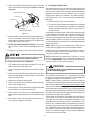
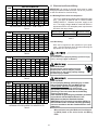
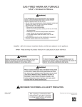
ARUF**14**/ARPT**14**
AIR HANDLERS
INSTALLATION & OPERATING INSTRUCTIONS
CONTENTS
1 Important Safety Instructions ........................................ 1
2 Important Note to the Owner
Regarding Product Warranty ....................................... 2
3 Shipping Inspection ...................................................... 3
3.1 Parts .................................................................... 3
3.2 Handling .............................................................. 3
4 Codes & Regulations .................................................... 3
5 Replacement Parts ....................................................... 3
6 Pre-Installation Considerations .................................... 3
6.1 Preparation .......................................................... 3
6.2 System Matches .................................................. 3
6.3 Interconnecting Tubing ........................................ 3
6.4 Clearances .......................................................... 4
6.5 Horizontal Applications ........................................ 4
7 Installation Location ..................................................... 4
7.1 Upflow Installation ................................................ 4
7.2 Horizontal Left Installation ................................... 4
7.3 Downflow Installation ........................................... 4
7.4 Horizontal Right Installation ................................. 5
8 Refrigerant Lines .......................................................... 7
8.1 Tubing Size .......................................................... 7
8.2 Tubing Preparation .............................................. 7
8.3 Special Instructions ............................................. 7
8.4 Tubing Connections for Flowrator Model ............. 7
8.5 Tubing Connections for TXV Models ................... 8
9 Condensate Drain Lines ............................................... 8
10 Ductwork ..................................................................... 9
10.1 Return Ductwork ................................................ 9
11 Return Air Filters ......................................................... 9
12 Electric Heat ............................................................... 9
12.1 No Electric Heat Installed .................................. 9
13 Electrical and Control Wiring .................................... 10
13.1 Building Electrical Service Inspection .............. 10
13.2 Wire Sizing ....................................................... 10
13.3 Maximum Overcurrent Protection (MOP) ........ 11
13.4 Electrical Connections – Supply Voltage ......... 11
13.4.1 Air Handler Only (Non-Heat Kit Models) ....... 11
13.4.2 Air Handler - Non-Circuit Breaker Heat Kits ... 11
13.4.3 Air Handler With Circuit Breaker Heat Kit ...... 11
13.5 Low Voltage Connections ................................ 11
13.5.1 Thermostats ............................................ 11
13.6 Speed Tap Adjustment ..................................... 12
14 Achieving 2% Low Leakage Rate ............................. 12
15 Start-Up Procedure ................................................... 12
16 Regular Maintenance ............................................... 12
Airflow Data ...................................................................... 13
Schematics ....................................................................... 14
©2012 Goodman Manufacturing Company, L.P.
5151 San Felipe, Suite 500, Houston, TX 77056
www.goodmanmfg.com - or - www.amana-hac.com
P/N: IO-427A Date: July 2012
RECOGNIZE THIS SYMBOL
AS A SAFETY PRECAUTION.
1 Important Safety Instructions
The following symbols and labels are used throughout this
manual to indicate immediate or potential safety hazards. It
is the owner’s and installer’s responsibility to read and comply with all safety information and instructions accompanying
these symbols. Failure to heed safety information increases
the risk of personal injury, property damage, and/or product
damage.
ATTENTION INSTALLING PERSONNEL
Prior to installation, thoroughly familiarize yourself with this Installation Manual.
Observe all safety warnings. During installation or repair, caution is to be observed.
It is your responsibility to install the product safely and to educate the customer on its safe use.
HIGH VOLTAGE!
To prevent the risk of property damage, personal
injury, or death, do not store combustible materials or
use gasoline or other flammable liquids or vapors in
the vicinity of this unit.
Disconnect ALL power before servicing.
Multiple power sources may be present.
Failure to do so may cause property damage,
personal injury or death.
Installation and repair of this unit should be performed
ONLY by individuals meeting the requirements of an
“entry level technician”, at a minimum, as specified by
the Air-Conditioning, Heating and Refrigeration Institute
(AHRI). Attempting to install or repair this unit without
such background may result in product damage,
personal injury or death.
CARBON MONOXIDE POISONING HAZARD
Special Warning for Installation of Furnace or Air Handling Units in
Enclosed Areas such as Garages, Utility Rooms or Parking Areas
This product is factory-shipped for use with
208/240/1/60 electrical power supply. DO NOT
reconfigure this air handler to operate with any other
power supply.
Carbon monoxide producing devices (such as an automobile, space
heater, gas water heater, etc.) should not be operated in enclosed areas
such as unventilated garages, utility rooms or parking areas because of
the danger of carbon monoxide (CO) poisoning resulting from the exhaust
emissions. If a furnace or air handler is installed in an enclosed area such
as a garage, utility room or parking area and a carbon monoxide producing
device is operated therein, there must be adequate, direct outside
ventilation.
To avoid property damage, personal injury or death
due to electrical shock, this unit MUST have an
uninterrupted, unbroken electrical ground. The
electrical ground circuit may consist of an
appropriately sized electrical wire connecting the
ground lug in the unit control box to the building
electrical service panel.
Other methods of grounding are permitted if performed
in accordance with the National Electric Code
(NEC)/American National Standards Institute
(ANSI)/National Fire Protection Association (NFPA) 70
and local/state codes. In Canada, electrical grounding
is to be in accordance with the Canadian Electric Code
(CSA) C22.1.
This ventilation is necessary to avoid the danger of CO poisoning which
can occur if a carbon monoxide producing device continues to operate in
the enclosed area. Carbon monoxide emissions can be (re)circulated
throughout the structure if the furnace or air handler is operating in any
mode.
CO can cause serious illness including permanent brain damage or death.
B10259-216
-
2
Important Note to the Owner Regarding Product
Warranty
Your warranty certificate is supplied as a separate document
with the unit installed by your contractor. Read the limited
warranty certificate carefully to determine what is and is not
covered and keep the warranty certificate in a safe place. If
you are unable to locate the warranty certificate please contact your installing contractor or contact customer service (877254-4729) to obtain a copy.
When installing or servicing this equipment, safety
clothing, including hand and eye protection, is
strongly recommended. If installing in an area that has
special safety requirements (hard hats, etc.), observe
these requirements.
IMPORTANT: To receive the 10 Year Parts Limited Warranty,
online registration must be completed within 60 days of installation. Online registration is not required in California or
Quebec. Complete warranty details are available from your
local dealer or, for Goodman® brand products, visit
www.goodmanmfg.com and for Amana® brand product, visit
www.amana-hac.com.
Do not connect to or use any device that is not designcertified by Goodman for use with this unit. Serious
property damage, personal injury, reduced unit
performance and/or hazardous conditions may result
from the use of such non-approved devices.
IMPORTANT: To register your Goodman® brand unit, go to
www.goodmanmfg.com and click “Warranty Registration”.
Complete registration as prompted.
is a registered trademark of Maytag Corporation or its related companies and is used under
license to Goodman Company, L.P., Houston, TX. All rights reserved.
2
To register your Amana® brand unit, go to www.amanahac.com and click “Warranty Registration”. Complete registration as prompted.
Product limited warranty certificates for models currently in
production can be viewed at www.goodmanmfg.com or
www.amana-hac.com. If your model is not currently in production or does not appear on the website, please contact
your installing contractor or contact customer service (877254-4729) to obtain a copy of your warranty certificate.
Each product overview page contains a Product Warranty
link; by clicking on it you will be able to view the limited warranty coverage for that specific product. To view warranty registration information, click on the Product Warranty text on
the left navigation panel on the home page of each website.
The Online Product Registration pages are located in this
same section.
Keep this literature in a safe place for future reference.
3 Shipping Inspection
Always transport the unit upright; laying the unit on its side or
top during transit may cause equipment damage. The installer
should inspect the product upon receipt for shipping damage
and subsequent investigation is the responsibility of the carrier. The installer must verify the model number, specifications, electrical characteristics, and accessories are correct
prior to installation. The distributor or manufacturer will not
accept claims from dealers for transportation damage or installation of incorrectly shipped units.
3.1 Parts
Also inspect the unit to verify all required components
are present and intact. Report any missing components
immediately to Goodman® or to the distributor. Use only
factory authorized replacement parts (see Section 5).
Make sure to include the full product model number and
serial number when reporting and/or obtaining service
parts.
3.2 Handling
Use caution when transporting/carrying the unit. Do not
move unit using shipping straps. Do not carry unit with
hooks or sharp objects. The preferred method of carrying the unit after arrival at the job site is to carry via a twowheel hand truck from the back or sides or via hand by
carrying at the cabinet corners.
4 Codes & Regulations
This product is designed and manufactured to comply with
applicable national codes. Installation in accordance with such
codes and/or prevailing local codes/regulations is the responsibility of the installer. The manufacturer assumes no responsibility for equipment installed in violation of any codes or regulations.
3
The United States Environmental Protection Agency
(EPA) has issued various regulations regarding the introduction and disposal of refrigerants. Failure to follow
these regulations may harm the environment and can
lead to the imposition of substantial fines. Should you
have any questions please contact the local office of the EPA
and/or refer to EPA’s website www.epa.gov.
5
Replacement Parts
When reporting shortages or damages, or ordering repair
parts, give the complete product model and serial numbers
as stamped on the product. Replacement parts for this product are available through your contractor or local distributor.
For the location of your nearest distributor consult the white
business pages, the yellow page section of the local telephone book or contact:
CONSUMER AFFAIRS
GOODMAN MANUFACTURING COMPANY, L.P.
7401 SECURITY WAY
HOUSTON, TEXAS 77040
(877) 254-4729
6
Pre-Installation Considerations
6.1 Preparation
Keep this document with the unit. Carefully read all instructions for the installation prior to installing product.
Make sure each step or procedure is understood and
any special considerations are taken into account before starting installation. Assemble all tools, hardware
and supplies needed to complete the installation. Some
items may need to be purchased locally. Make sure everything needed to install the product is on hand before
starting.
6.2 System Matches
The entire system (combination of indoor and outdoor
sections) must be manufacturer approved and Air-Conditioning, Heating, and Refrigeration Institute (AHRI)
listed. NOTE: Installation of unmatched systems is not
permitted and will void the product warranty.
6.3 Interconnecting Tubing
Give special consideration to minimize the length of refrigerant tubing when installing air handlers. Refer to Remote Cooling/Heat Pump Service Manual RS6200006,
and TP-107 Long Line Set Application R-410A for tubing guidelines. If possible, allow adequate length of tubing such that the coil may be removed (for inspection or
cleaning services) from the cabinet without disconnecting the tubing.
7.2 Horizontal Left Installation
6.4 Clearances
No field modifications are permissible for this application.
The unit clearance from a combustible surface may be
0". However, service clearance must take precedence.
A minimum of 24" in front of the unit for service clearance is required. Additional clearance on one side or
top will be required for electrical wiring connections. Consult all appropriate regulatory codes prior to determining
final clearances. When installing this unit in an area that
may become wet (such as crawl spaces), elevate the
unit with a sturdy, non-porous material. In installations
that may lead to physical damage (i.e. a garage) it is
advised to install a protective barrier to prevent such damage. Always install units such that a positive slope in condensate line (1/4" per foot) is allowed.
The bottom right drain connection is the primary drain for
this application and condensate drain line must be attached to this drain connection. The top connection of
the three drain connections on the drain pan must remain plugged for this application. The bottom left drain
connection is for the secondary drain line (if used).
7.3 Downflow Installation
IMPORTANT NOTE: To prevent the coil pan from “sweating”, the DPI accessory insulation kit must be used when
performing this conversion. The DPI kit is not supplied
with this product and is to be purchased separately. See
Table 1 for the correct DPI kit. Follow the instructions
provided in the kit for appropriate installation.
6.5 Horizontal Applications
If installed above a finished living space, a secondary
drain pan (as required by many building codes), must be
installed under the entire unit and its condensate drain
line must be routed to a location such that the user will
see the condensate discharge.
7
MODEL LIST FOR DRAIN PAN INSULATION KITS
DPI-B
DPI-C
DPI-D
Insulation Kit
Insulation Kit
Insulation Kit
Installation Location
NOTE: These air handlers are designed for indoor installation only.
The ARUF**14**/ARPT**14** product line may be installed
in one of the upflow, downflow, horizontal left or horizontal
right orientations as shown in Figures 1, 2, 3 and 4. The unit
may be installed in upflow or horizontal left orientation as
shipped (refer to specific sections for more information). Field
modifications are necessary to convert to downflow or horizontal right as indicated in below sections.
ARUF18B14**
ARUF36C14**
ARUF48D14**
ARUF24B14**
ARUF42C14**
ARUF60D14**
ARUF30B14**
ARPT36C14**
ARPT36D14**
ARPT18B14**
ARPT42D14**
ARPT24B14**
ARPT48D14**
ARPT30B14**
ARPT60D14**
DOWNFLOW INSULATION KIT
Table 1
Refer to Figure 5 and 6 for the location of the components referenced in the following steps.
7.1 Upflow Installation
No field modifications are mandatory however to obtain
maximum rated efficiency, the horizontal drip shield must
be removed. Without removal of the horizontal drip shield,
performance will be reduced by up to a few percentage
points.
1. Before inverting the air handler, remove blower access
panel and coil access panel. The coil access panel and
tubing panel may remain screwed together during this
procedure. Remove and retain the seven (7) screws securing the coil access panel to the cabinet and the six
(6) screws securing the blower access panel to the cabinet.
Drip Shield Removal: Refer to Figure 9, remove the two
(2) screws that secure the drip shield support brackets to
the condensate collectors (one screw per side). Remove
the two (2) screws that secure the drip shield to the drain
pan. The drip shield and drip shield brackets may now
be removed.
2. Slide the coil assembly out using the drain pan to pull
the assembly from the cabinet.
NOTE: DO NOT USE MANIFOLDS OR FLOWRATOR
TO PULL THE COIL ASSEMBLY OUT. FAILURE TO
DO SO MAY RESULT IN BRAZE JOINT DAMAGE
AND LEAKS.
The bottom left drain connection is the primary drain for
this application and condensate drain line must be attached to this drain connection. The top connection of
the three drain connections on the drain pan must remain plugged for this application. The bottom right drain
connection is for the secondary drain line (if used).
3. Referring to Figure 9, remove the two (2) screws that
secure the drip shield support brackets to the condensate collectors (one screw per side). Remove the (2)
two screws that secure the drip shield to the drain pan.
The drip shield and drip shield brackets may now be
removed.
4. Removal of the center support is required on units with
21" wide cabinet. Remove and retain the two (2) screws
that secure the center support to the cabinet. Remove
the center support.
4
5. Using the drain pan to hold the coil assembly, slide the
coil assembly back into the cabinet on the downflow
brackets as shown in Figure 7.
6. Re-install the center support (if removed) using the two
(2) screws removed in Step 4.
7. Re-install the access panels removed in Step 1 as shown
in Figure 8.
8. The bottom left drain connection is the primary drain for
this application and condensate drain line must be attached to this drain connection. The top connection of
the three drain connections on the drain pan must remain plugged for this application. The bottom left drain
connection is for the secondary drain line (if used).
7.4 Horizontal Right Installation
Horizontal right conversion is similar to Downflow conversion.
Refer to Figure 5 and 6 for the location of the components referenced in the following steps.
1. Remove blower access panel and coil access panel.
The coil access panel and tubing panel may remain
screwed together during this procedure. Remove and
retain the seven (7) screws securing the coil access
panel to the cabinet and the six (6) screws securing the
blower access panel to the cabinet.
UPFLOW
DOWNFLOW
Figure 1
Figure 2
2. Slide the coil assembly out using the drain pan to pull
the assembly from the cabinet.
NOTE: DO NOT USE MANIFOLDS OR FLOWRATOR
TO PULL OUT THE COIL ASSEMBLY. FAILURE TO
DO SO MAY RESULT IN BRAZE JOINT DAMAGE
AND LEAKS.
3. Removal of the center support is required on units with
21" wide cabinet. Remove and retain the two (2) screws
that secure the center support to the cabinet. Remove
the center support.
HORIZONTAL LEFT
Figure 3
4. Using the drain pan to hold the coil assembly, slide the
coil assembly back into the cabinet on the downflow
brackets as shown in Figure 7.
5. Re-install the center support (if removed) using the two
(2) screws removed in Step 5 (refer to Figure 5).
6. Re-install the access panels removed in Step 1 as
shown in Figure 8.
7. The bottom right drain connection is the primary drain
for this application and condensate drain line must be
attached to this drain connection. The top connection of
the three drain connections on the drain pan must remain plugged for this application. The bottom left drain
connection is for the secondary drain line (if used).
HORIZONTAL RIGHT
Figure 4
5
Upper Tie Plate
Control
Deck
Coil Slides
on the
downflow bracket
Downflow
Bracket
Center
Support
Filter
Bracket
Filter Access
Panel
IMPORTANT NOTE:
Ensure coil slides on the rails
along the groove provided
on the drain pan side walls.
Failure to do so will result
in improper condensate drainage.
INTERNAL PART TERMINOLOGY
Figure 5
Blower
Access
Panel
COIL INSTALLATION FOR DOWNFLOW
Figure 7
Coil
Access
Panel
Secondary
Drain Port
for Horizontal
Application
Thumb
Screw
Secondary Drain Port
for Upflow/Downflow
Application
Tubing
Panel
EXTERNAL PART TERMINOLOGY
ACCESS PANEL CONFIGURATION FOR DOWNFLOW
Figure 6
OR HORIZONTAL RIGHT
Figure 8
6
CAUTION
Screw
Applying too much heat to any tube can melt the tube. Torch
heat required to braze tubes of various sizes must be
proportional to the size of the tube. Service personnel must
use the appropriate heat level for the size of the tube being
brazed.
8.3 Special Instructions
Units without a factory installed TXV come equipped
with a flowrator piston for refrigerant expansion. For
most installations with matching applications, no
change to the flowrator piston is required. However, in
mix-matched applications, a flowrator piston change
may be required. See the Goodman® piston kit chart
(provided in the literature packet) or consult your local
distributor for details regarding mix-matched flowrator
piston sizing. If the mix-match application requires a
different flowrator piston size, change the flowrator piston in the flowrator body on the indoor coil before installing the coil and use the procedure in section 8.4.
Screw
DRIP SHIELD REMOVAL
Figure 9
8 Refrigerant Lines
NOTE: The use of a heat shield is strongly recommended when brazing to avoid burning the serial plate
or the finish of the unit. Heat trap or wet rags must be
used to protect heat sensitive components such as service valves and TXV valves sensing bulb.
This product is factory-shipped with R410A and dry
nitrogen mixture gas under pressure. Use appropriate
service tools and follow these instructions to prevent
injury.
8.4 Tubing Connections for Flowrator Model
A quenching cloth is strongly recommended to prevent
scorching or marring of the equipment finish when
brazing close to the painted surfaces. Use brazing
alloy of 5% minimum silver content.
1. Loosen the 13/16 nut 1 TURN ONLY to allow high pressure tracer gas to escape. No gas indicates a possible
leak.
2. After the gas has been expelled, remove the nut and
discard the black or brass cap plastic seal.
NOTE: Refrigerant tubing must be routed to allow adequate
access for servicing and maintenance of the unit.
Do not install the air handler in a location that violates the
instructions provided with the condenser. If the unit is located
in an unconditioned area with high ambient temperature and/
or high humidity, the air handler may be subject to nuisance
sweating of the casing. On these installations, a wrap of 2"
fiberglass insulation with a vapor barrier is recommended.
8.1 Tubing Size
3. Remove the flowrator piston to verify it is the correct
size for the outdoor unit being installed and then replace
the piston (changing size, if needed). See piston kit chart
in the literature kit for appropriate piston size.
4. Remove the spin closure on the suction line using a
tube cutter and deburr the tube.
5. Insert the suction line into the connection, slide the insulation and the rubber grommet at least 18" away from
the braze joint.
For the correct tubing size, follow the specification for
the condenser/heat pump.
8.2 Tubing Preparation
SUCTION LINE
WITH SPIN CLOSURE
All cut ends are to be round, burr free, and clean. Failure
to follow this practice increases the chances for refrigerant leaks. The suction line is spun closed and requires
tubing cutters to remove the closed end.
RUBBER
GROMMET
NOTE: To prevent possible damage to the tubing joints,
do not handle coil assembly with manifold or flowrator
tubes. Always use clean gloves when handling coil assemblies.
SUCTION SPUN END AND GROMMET
Figure 10
7
6. Remove the tailpiece clamped to the exterior of the cabinet or in the literature kit packet and slide the 13/16 nut
into place.
9
Condensate Drain Lines
The coil drain pan has a primary and a secondary drain with
3/4" NPT female connections. The connectors required are
3/4" NPT male, either PVC or metal pipe, and should be hand
tightened to a torque of no more than 37 in-lbs. to prevent
damage to the drain pan connection. An insertion depth of
approximately 3/8” to 1/2” (3-5 turns) should be expected at
this torque.
PLASTIC or BRASS CAP
13/16” NUT
TAILPIECE
1. Ensure drain pan hole is not obstructed.
WHITE
TEFLON SEAL
2. To prevent potential sweating and dripping on to finished
space, it may be necessary to insulate the condensate
drain line located inside the building. Use Armaflex® or
similar material.
A secondary condensate drain connection has been provided
for areas where the building codes require it. Pitch all drain
lines a minimum of 1/4" per foot to provide free drainage.
Provide required support to the drain line to prevent bowing.
If the secondary drain line is required, run the line separately
from the primary drain and end it where condensate discharge
can be easily seen.
NOTE: Water coming from secondary line means the coil
primary drain is plugged and needs immediate attention.
PISTON
TAILPIECE JOINT
Figure 11
7. Braze tailpiece to the line set liquid tube and braze suction line connection. Quench all brazed joints with a
damp rag upon completion of brazing. Do not allow water
to enter the inside of the tubing.
8. AFTER THE TAILPIECE HAS COOLED, confirm position of the white Teflon® seal and hand tighten the 13/16
nut.
Insulate drain lines located inside the building or above a
finished living space to prevent sweating. Install a condensate trap to ensure proper drainage.
9. Torque the 13/16 nut to 7-25 ft-lbs. or tighten 1/6 turn.
NOTE: When units are installed above ceilings, or in other
locations where damage from condensate overflow may
occur, it is MANDATORY to install a field fabricated auxiliary
drain pan under the coil cabinet enclosure.
Excessive torque can cause orifices to stick. Use the
proper torque settings when tightening orifices.
8.5 Tubing Connections for TXV Models
TXV models come with factory installed TXV with the
bulb pre-installed on the vapor tube.
CAUTION
If secondary drain is not installed, the secondary
access must be plugged.
1. Remove refrigerant tubing panel or coil (lower) access
panel.
2. Remove access valve fitting cap and depress the valve
stem in access fitting to release pressure. No pressure
indicates possible leak.
The installation must include a “P” style trap that is located
as close as is practical to the evaporator coil. See Figure 12
for details of a typical condensate line “P” trap.
NOTE: Trapped lines are required by many local codes. In
the absence of any prevailing local codes, please refer to the
requirements listed in the Uniform Mechanical Building Code.
A drain trap in a draw-through application prevents air from
being drawn back through the drain line during fan operation
thus preventing condensate from draining, and if connected
to a sewer line to prevent sewer gases from being drawn into
the airstream during blower operation.
Field experience has shown condensate drain traps with an
open vertical Tee between the air handler and the condensate drain trap can improve condensate drainage in some
applications, but may cause excessive air discharge out of
the open Tee. Goodman® does not prohibit this type of drain
but we also do not recommend it due to the resulting air leakage. Regardless of the condensate drain design used, it is
the installer’s responsibility to ensure the condensate drain
system is of sufficient design to ensure proper condensate
removal from the coil drain pan.
3. Replace the refrigerant tubing panel.
4. Remove the spin closure on both the liquid and suction
tubes using a tubing cutter.
5. Insert liquid line set into liquid tube expansion and slide
grommet about 18" away from braze joint.
6. Insert suction line set into suction tube expansion and
slide insulation and grommet about 18" away from braze
joint.
7. Braze joints. Quench all brazed joints with water or a
wet rag upon completion of brazing.
8
11 Return Air Filters
Drain
Connection
Air Handler
Each installation must include a return air filter. This filtering
may be performed at the air handler using the factory filter
rails or externally such as a return air filter grille. When using
the factory filter rails, a nominal 16x20x1”, 20x20x1” or
24x20x1” (actual dimension must be less than 23-½”x20”)
filter can be installed on a B, C and D cabinet respectively
(the cabinet size is the seventh letter of the model number).
2" MIN.
POSITIVE LIQUID
SEAL REQUIRED
AT TRAP
3" MIN.
12 Electric Heat
Refer to the installation manual provided with the electric heat
kit for the correct installation procedure. All electric heat must
be field installed. If installing this option, the ONLY heat kits
that are permitted to be used are the HKS series. Refer to
the air handler unit’s Serial and Rating plate or the HKS specification sheets to determine the heat kits compatible with a
given air handler. No other accessory heat kit besides the
HKS series may be installed in these air handlers.
Figure 12
Use of a condensate removal pump is permitted when necessary. This condensate pump should have provisions for
shutting off the control voltage should a blocked drain occur.
A trap must be installed between the unit and the condensate pump.
IMPORTANT NOTE: The evaporator coil is fabricated with
oils that may dissolve styrofoam and certain types of plastics.
Therefore, a removal pump or float switch must not contain
any of these materials.
Tip: Priming the “P” trap may avoid improper draining at the
initial installation and at the beginning of the cooling season.
The heating mode temperature rise is dependent upon the
system airflow, the supply voltage, and the heat kit size (kW)
selected. Use data provided in Tables 2, 3 and 4 to determine the temperature rise (°F).
NOTE: For installations not indicated above the following
formula is to be used:
10 Ductwork
TR = (kW x 3412) x (Voltage Correction) x 1.08 / CFM
Where:
TR
= Temperature Rise
kW = Heater Kit Actual kW
3412 = Btu per kW
VC* = .96 (230 Supply Volts)
= .92 (220 Supply Volts)
= .87 (208 Supply Volts)
1.08 = Constant
CFM = Measured Airflow
This air handler is designed for a complete supply and return
ductwork system.
To ensure correct system performance, the ductwork is to be
sized to accommodate 350-450 CFM per ton of cooling with
the static pressure not to exceed 0.5" in w.c. Refer to ACCA
Manual D, Manual S and Manual RS for information on duct
sizing and application. Flame retardant ductwork is to be
used and sealed to the unit in a manner that will prevent leakage.
NOTE: A downflow application with electric heat must have
an L-shaped sheet metal supply duct without any outlets or
registers located directly below the heater.
*VC (Voltage Correction)
NOTE: The Temperature Rise Tables can also be used to
estimate the air handler airflow delivery. When using these
tables for this purpose set the room thermostat to maximum
heat and allow the system to reach steady state conditions.
Insert two thermometers, one in the return air and one in the
supply air. The temperature rise is the supply air temperature
minus the room air temperature. Using the temperature rise
calculated, CFM can be estimated from the TR formula above.
See Technical Manual and/or Service Manual for more
information.
10.1 Return Ductwork
DO NOT LOCATE THE RETURN DUCTWORK IN AN
AREA THAT CAN INTRODUCE TOXIC, OR OBJECTIONABLE FUMES/ODORS INTO THE DUCTWORK.
The return ductwork is to be connected to the air handler bottom (upflow configuration).
Do not operate this product without all the ductwork
attached.
12.1 No Electric Heat Installed
If no electric heat accessory kit is installed, a cover plate
must be installed over the opening for electric heat. This
cover plate kit is available from Goodman® and Amana®
brand distributors.
9
CFM
800
1000
1200
1400
1600
1800
2000
13 Electrical and Control Wiring
HEAT KIT NOMINAL kW
3
12
9
8
7
6
5
5
5
19
15
12
11
9
8
7
6
23
19
15
13
12
10
9
8
31
25
21
18
15
14
12
10
37
30
25
21
19
16
15
15
19/20
25
44
37
32
28
25
22
IMPORTANT: All routing of electrical wiring must be made
through provided electrical knockouts. Do not cut, puncture
or alter the cabinet for electrical wiring.
49
42
37
33
30
62
53
46
41
37
13.1 Building Electrical Service Inspection
This unit is designed for single-phase electrical supply
only. DO NOT OPERATE ON A THREE-PHASE
POWER SUPPLY. Measure the power supply to the
unit. The supply voltage must be measured and be in
agreement with the unit nameplate power requirements
and within the range shown.
230/1/60 SUPPLY VOLTAGE - TEMP. RISE °F
Table 2
CFM
800
1000
1200
1400
1600
1800
2000
HEAT KIT NOMINAL kW
3
11
9
7
6
6
5
4
5
18
14
12
10
9
8
7
6
22
18
15
13
11
10
9
8
30
24
20
17
15
13
12
10
35
28
24
20
18
16
14
15
19/20
25
Nominal Input
Minimum Voltage
Maximum Voltage
208 - 240
197
253
ELECTRICAL VOLTAGE
42
35
30
27
24
21
Table 6
47
40
35
31
28
59
51
44
39
35
13.2 Wire Sizing
Wire size is important to the operation of your equipment. Use the following check list when selecting the
appropriate wire size for your unit.
220/1/60 SUPPLY VOLTAGE - TEMP. RISE °F
Table 3
CFM
800
1000
1200
1400
1600
1800
2000
FIRE HAZARD!
To avoid the risk of property damage, personal injury
or fire, use only copper conductors.
HEAT KIT NOMINAL kW
3
10
8
7
6
5
5
4
5
17
13
11
10
8
7
7
6
21
17
14
12
10
9
8
8
28
22
19
16
14
12
11
10
33
27
22
19
17
15
13
15
19/20
25
40
33
29
25
22
20
45
38
33
30
27
56
48
42
37
33
HIGH VOLTAGE!
Disconnect ALL power before servicing.
Multiple power sources may be present.
Failure to do so may cause property damage,
personal injury or death.
208/1/60 SUPPLY VOLTAGE - TEMP. RISE °F
Table 4
HIGH VOLTAGE!
To avoid property damage, personal injury or death
due to electrical shock, this unit MUST have an
uninterrupted, unbroken electrical ground. The
electrical ground circuit may consist of an
appropriately sized electrical wire connecting the
ground lug in the unit control box to the building
electrical service panel.
Other methods of grounding are permitted if performed
in accordance with the National Electric Code
(NEC)/American National Standards Institute
(ANSI)/National Fire Protection Association (NFPA) 70
and local/state codes. In Canada, electrical grounding
is to be in accordance with the Canadian Electric Code
(CSA) C22.1.
HEATER (kW)
*ARUF
ARPT
3
5
6
8
10
18
715
715
715
715
950
24
715
715
715
715
950
30
715
715
715
715
875
15
19
20
25
875
36
1170 1170 1170 1170 1345
1345
42
1170 1170 1170 1170 1345
1345
48
1590 1590 1590 1590 1715
1715 1715
60
1590 1590 1590 1590 1715
1715 1715
*Table applies to ARUF**14** & ARPT**14**
MINIMUM CFM REQUIRED FOR HEATER KITS
Table 5
•
10
Wire used must carry the Minimum Circuit Ampacity (MCA) listed on the unit’s Series and Rating
Plate.
•
Refer to the NEC (USA) or CSA (Canada) for wire sizing. The unit MCA for the air handler and the optional
electric heat kit can be found on the unit Series and
Rating Plate.
•
Wire must be sized to allow no more than a 2% voltage drop from the building breaker/fuse panel to
the unit.
•
Wires with different insulation temperature rating have
varying ampacities - be sure to check the temperature
rating used.
Refer to the latest edition of the National Electric Code
or in Canada the Canadian Electric Code when determining the correct wire size.
13.3 Maximum Overcurrent Protection (MOP)
Every installation must include an NEC (USA) or CEC
(Canada) approved overcurrent protection device.
Also, check with local or state codes for any special
regional requirements.
Protection can be in the form of fusing or HACR style
circuit breakers. The Series and Rating Plate provides
the maximum overcurrent device permissible.
NOTE: Fuses or circuit breakers are to be sized larger
than the equipment MCA but not to exceed the MOP.
13.4 Electrical Connections – Supply Voltage
IMPORTANT NOTE: USE COPPER CONDUCTORS
ONLY.
Knockouts are provided on the air handler top panel
and sides of the cabinet to allow for the entry of the
supply voltage conductors, as shown in Figure 13. If
the knockouts on the cabinet sides are used for electrical conduit, an adapter ring must be used in order to
meet UL1995 safety requirements. An NEC or CEC
approved strain relief is to be used at this entry point.
Some codes/municipalities require the supply wire to
be enclosed in conduit. Consult your local codes.
Top of
Cabinet
13.4.1 Air Handler Only (Non-Heat Kit Models)
The power supply connects to the stripped black and
red wires contained in the air handler electrical compartment. Attach the supply wires to the air handler
conductors as shown in the unit wiring diagram using
appropriately sized solderless connectors or other NEC
or CEC approved means. A ground lug is also provided in the electrical compartment. The ground wire
from the power supply must be connected to this ground
lug.
13.4.2 Air Handler - Non-Circuit Breaker Heat Kits
A terminal block is provided with the HKS kit to attach
the power supply and air handler connections. Follow
the HKS Installation Manual and wiring diagram for
complete wiring details.
13.4.3 Air Handler With Circuit Breaker Heat Kit
The air handler has a plastic cover on the upper access panel that will require either one or both sections
to be removed to allow the heat kit circuit breaker(s) to
be installed. The circuit breakers have lugs for power
supply connection. See the HKS Installation Instructions for further details.
13.5 Low Voltage Connections
Several combinations of low voltage schemes are possible, depending on the presence of a heat kit and
whether the heat kit is single-stage or multi-stage,
whether the outdoor section is an air conditioner or heat
pump, and whether the outdoor section is single-stage
or two-stage. The 24V-control voltage connects the air
handler to the room thermostat and condenser. Low
voltage wiring must be copper conductors. A minimum
of 18AWG must be used for installations up to 50’ and
16AWG for installations over 50’. Low voltage wiring
must be connected through the top of the cabinet or
either side. See the “Thermostat Wiring” section of
this manual for typical low voltage wiring connections.
13.5.1 Thermostats
Second-stage heat can be accomplished by a multistage heating thermostat or the addition of an outdoor
thermostat as shown in wiring schematics on pages
14 and 15. Follow the thermostat manufacturer’s instructions for installation.
Side of
Cabinet
KNOCK-OUT FOR ELECTRICAL CONNECTIONS
Figure 13
11
13.6 Speed Tap Adjustment
ARUF**14** and ARPT**14** air handlers have multispeed PSC motors. The color of the wire coming from
the motor to the “COM” terminal on the control board
defines at which speed the motor will operate. Black
wire is high speed, blue wire is medium speed and red
wire is low speed. To change speeds, remove the wire
attached to the “COM” terminal on the control board,
and swap it with the wire (on terminal “M1” or “M2”)
with the color that will give the desired speed.
NOTE: In some models, not all speed taps are allowable for certain electric heat applications. Refer to air
handler Series and Ratings plate for minimum speed.
•
Low voltage wiring is properly connected.
•
Auxiliary drain is installed when necessary and pitched
to allow for drainage.
•
Unit is protected from vehicular or other physical damage.
•
Return air is not obtained from, nor are there any return air duct joints that are unsealed in, areas where
there may be objectionable odors, flammable vapors
or products of combustion such as carbon monoxide
(CO), which may cause serious personal injury or death.
16 Regular Maintenance
14 Achieving 2% Low Leakage Rate
Ensure all the gaskets remain intact on all surfaces as shipped
with the unit. These surfaces are areas between the upper
tie plate and control deck, blower access and coil access
panels, coil access and filter access panels. Be sure that the
blower access panel breaker insert gasket is intact. With
these gaskets in place, the unit achieves less than 2% airflow leakage when tested in accordance with ASHRAE Standard 193.
15 Start-Up Procedure
•
Prior to start-up, ensure that all electrical wires are properly sized and all connections are properly tightened.
•
All panels must be in place and secured. For Air Tight
application, gasket must be positioned at prescribed
locations to achieve 2% leakage.
•
Tubing must be leak free.
•
Condensate line must be trapped and pitched to allow
for drainage.
12
HIGH VOLTAGE!
Disconnect ALL power before servicing or
installing this unit. Multiple power sources may
be present. Failure to do so may cause property
damage, personal injury or death.
The only item required to be maintained on a regular basis
by the user is the circulating air filter(s). Filter should be
cleaned or replaced regularly, typically once per month. A
certified service technician must perform all other services.
IMPORTANT NOTE: If thumb screws are used to access the
filter, ensure the washer installed on the screw behind the
access panel remains in place after re-installation.
Airflow Data
Model Number
ARUF18B14
ARUF24B14
ARUF30B14
ARUF36C14
ARUF42C14
ARUF48D14
ARUF60D14
Blower
Speed
High
Medium
Low
High
Medium
Low
High
Medium
Low
High
Medium
Low
High
Medium
Low
High
Medium
Low
High
Medium
Low
0.1
1150
890
640
0.2
1095
855
605
Static Pressure (in w.c)
0.3
0.4
0.5
1045
1025
950
835
775
715
565
530
485
0.6
865
665
440
0.7
775
605
360
1150
890
640
1095
855
605
1045
835
565
1025
775
530
950
715
485
865
665
440
775
605
360
1145
870
615
1085
820
585
1020
775
565
950
745
535
900
705
490
845
655
435
765
580
345
1485
1300
1040
1435
1270
1015
1385
1235
980
1345
1195
930
1275
1130
865
1205
1060
790
1125
955
705
1580
1395
1095
1530
1340
1045
1465
1290
1000
1400
1235
950
1330
1170
895
1255
1095
820
1165
1000
725
1990
1655
1480
1915
1605
1420
1810
1555
1350
1765
1480
1290
1690
1295
1185
1585
1200
1100
1435
1060
1045
2235
2030
1615
2175
1970
1535
2125
1885
1455
2050
1800
1355
1960
1690
1270
1825
1600
1185
1720
1495
1090
AIRFLOW DATA (CFM) FOR ARUF**14** MODELS
Table 7
Model Number
Blower
Speed
ARPT18B14
Static Pressure (in w.c)
High
Medium
Low
0.1
1185
900
630
0.2
1125
850
605
0.3
1065
825
560
0.4
1010
785
525
0.5
985
715
495
0.6
910
670
445
0.7
780
610
355
ARPT24B14
High
Medium
Low
1185
900
630
1125
850
605
1065
825
560
1010
785
525
985
715
495
910
670
445
780
610
355
ARPT30B14
High
Medium
Low
1145
870
615
1085
820
585
1020
775
565
950
745
535
900
705
490
845
655
435
765
580
345
High
Medium
Low
High
Medium
Low
High
Medium
Low
High
Medium
Low
High
Medium
Low
1580
1385
1260
1515
1350
1205
1445
1300
1175
1395
1250
1105
1345
1170
1040
1240
1095
975
1155
1005
865
1815
1580
1220
1770
1525
1180
1705
1485
1140
1640
1420
1085
1555
1350
1030
1450
1275
950
1355
1165
865
1990
1655
1480
1915
1605
1420
1810
1555
1350
1765
1480
1290
1690
1295
1185
1585
1200
1100
1435
1060
1045
1960
1600
1395
1905
1545
1340
1845
1495
1280
1780
1435
1220
1715
1360
1150
1645
1290
1090
1570
1215
1020
2205
1985
1600
2140
1935
1555
2080
1865
1505
2010
1815
1455
1945
1755
1405
1870
1695
1345
1795
1635
1295
ARPT36C14
ARPT36D14
ARPT42D14
ARPT48D14
ARPT60D14
AIRFLOW DATA (CFM) FOR ARPT**14** MODELS
Table 8
Notes: • Airflow data indicated is 230V without air filter in place.
• The chart is for information only. For satisfactory operation, external static pressure must not exceed value shown on rating plate. The shaded
area indicates ranges in excess of maximum design external static pressure.
• Use the CFM adjustment factors of 0.98 for horizontal left and 0.96 for horizontal right & downflow orientations.
13
Schematics
WARNING
HIGH VOLTAGE! DISCONNECT ALL POWER BEFORE SERVICING.
MULTIPLE POWER SOURCES MAY BE PRESENT. FAILURE TO DO SO
MAY CAUSE PROPERTY DAMAGE, PERSONAL INJURY OR DEATH.
ROOM THERMOSTAT
W
Y
G
#18 GA. 4 WIRES WITH
COOLING 3 WIRES WITHOUT
R
AR UNIT
R
G
W
RED
GREEN
WHITE
Y
CONTACTOR TO CONDENSING
COIL
UNIT 24V. CONNECTIONS
BLUE
#18 GA. 2 WIRES
Low Voltage Wiring Diagram for Cooling Unit with optional heat kit 10kW and below
AR UNIT
W2
#18 GA. 4 WIRE WITH
COOLING 3 WIRE WITHOUT
RED
GREEN
WHITE
#18 GA. 2 WIRES
CONTACTOR CONDENSING
UNIT 24V. CONNECTIONS
COIL
BROWN
BLUE
Low Voltage Wiring Diagram for Cooling Unit with optional heat kit 15kW and above
Wiring is subject to change. Always refer to the wiring diagram on the unit for the most up-to-date wiring.
14
HIGH VOLTAGE! DISCONNECT ALL POWER BEFORE SERVICING.
MULTIPLE POWER SOURCES MAY BE PRESENT. FAILURE TO DO SO
MAY CAUSE PROPERTY DAMAGE, PERSONAL INJURY OR DEATH.
WARNING
ARUF**14**/ARPT**14**
18-60
10 KW & BELOW
TYPICAL H/P
ROOM THERMOSTAT
HEAT PUMP
C
Y O C
O Y
B
#18 GA. 7 WIRE
AT/AR UNIT
G R E
R
R
I
R
Y
R
R
RED
G
G
GREEN
BR
W
W
WHITE
BL
BL
BLUE
O
NOTE
W
BL
#18 GA. 5 WIRE
(OPTIONAL)
OUTDOOR THERMOSTAT
CLOSE ON TEMPERATURE FALL
#18 GA. 6 WIRE NEEDED WHEN OT IS USED
ARUF**14**/ARPT**14**
18-60
ABOVE 10 KW
TYPICAL H/P
ROOM THERMOSTAT
HEAT PUMP
C
O Y R
B
Y O C
G
R
#18 GA. 7 WIRE
AT/AR UNIT
E
R
R
I
R
R
R
RED
G
G
GREEN
W
WHITE
BR
Y
O
NOTE
W
NOTE
BR BROWN
BL
BL
BL
BLUE
#18 GA. 5 WIRE
(OPTIONAL)
OUTDOOR THERMOSTAT
CLOSE ON TEMPERATURE FALL
#18 GA. 7 WIRE NEEDED WHEN TWO OT'S ARE USED
IMPORTANT: If outdoor thermostat is not used, tie white and brown wires from Air Handler together.
Wiring is subject to change. Always refer to the wiring diagram on the unit for the most up-to-date wiring.
15
WARNING
HIGH VOLTAGE! DISCONNECT ALL POWER BEFORE SERVICING.
MULTIPLE POWER SOURCES MAY BE PRESENT. FAILURE TO DO SO
MAY CAUSE PROPERTY DAMAGE, PERSONAL INJURY OR DEATH.
ELECTRONIC BLOWER TIME DELAY RELAY
G
TSTAT
120/240VAC
R
SYSTEM
TRANSFORMER
K1
XFMR-R
M1
PARK TERMINAL
MOTOR
24 VAC
XFMR-C
B13707-35
WIRING DIAGRAM
NEUTRAL
K1
FOR USE WITH
C
HEAT KIT
OPTIONAL
SPEEDUP
SPEEDUP
The Electronic Blower Time Delay Relay provides power to the blower motor with a delay of 7
seconds after 24VAC is applied to “G”. After 24VAC is removed from “G”, the blower motor output
is de-energized after a delay of 65 seconds.
Normal Time Delays
Turn On Delay
Turn Off Delay
60Hz
50Hz
7.0 SEC.±1%
8.4 SEC. .±1%
65.0 SEC.±1% 78.0 SEC. .±1%
Field test mode: Shorting the “speedup” quick connect to “C” decrease times as follows:
Speedup Times
Turn On Delay
Turn Off Delay
60Hz
3.0 SEC.±1%
5.0 SEC.±1%
50Hz
3.6 SEC. .±1%
6.0 SEC. .±1%
Field test mode is cancelled when the “speedup” quick connect to “C” short is removed.
Wiring is subject to change. Always refer to the wiring diagram on the unit for the most up-to-date wiring.
16
HIGH VOLTAGE! DISCONNECT ALL POWER BEFORE SERVICING.
MULTIPLE POWER SOURCES MAY BE PRESENT. FAILURE TO DO SO
MAY CAUSE PROPERTY DAMAGE, PERSONAL INJURY OR DEATH.
WARNING
ARUF**14**/ARPT**14**
FL
FL
FL
FL
HTR2 TL
FL
HTR1 TL
FL
HTR1 TL
FL
FL
HTR1 TL
RD
BK
BK
BK
HTR2 TL
FL
RD
BK
BK
BK
HTR2 TL
RD
HTR3 TL
FL
1
HTR1 TL
YL
HTR3 TL
1
BK
2
HTR4 TL
1
BL
BK
RD
2
PU
BK
3
BL
YL
PU
4
M1
BK
R
RD
M1
M3
4
M2
M4
5
RD
M2
M4
WH
4
M2
M2
M3
M4
M5
M7
M6
M8
R1
RD
3
WH
RD
BL
R2
BR
4
5
BK
6
BK
6
RD
WH
6
7
7
BK
8
RD
5
BR
RD
BK
RD
M1
YL
R2
2
BK RD
BK
BK
7
BK
BL
BL
RD
BL
M1
R1
6
BK
M3
PU
3
BL
M1
R
WH
PU
3
1
2
YL
BK
BL
5
M2
RD
RD
7
YL
8
RD
YL
BK
8
RD
9
BL
BK
9
8
RD
9
9
L1
L2
L1
ONE (1) ELEMENT ROWS
L2
L1
TWO (2) ELEMENT ROWS
L2
L1
L2
THREE (3) ELEMENT ROWS
L1
L2
L1
L2
FOUR (4) ELEMENT ROWS
NOTE: WHEN INSTALLING HEATER KIT, ENSURE SPEED TAP IS NOT BELOW MINIMUM BLOWER SPEED (MBS) SPECIFIED FOR THE AIR HANDLER/HEATER KIT
COMBINATION ON THIS UNITS SERIAL PLATE. AFTER INST ALLING OPTIONAL HEAT KIT, MARK A "X" IN THE
PROVIDED ABOVE. MARK ACCORDING TO THE
NUMBER OF HEATER ELEMENT ROWS INSTALLED. NO MARK INDICATES NO HEAT KIT INSTALLED. 5 ELEMENT ROWS DATA SUPPLIED WITH HEATER KIT.
SEE NOTE 2
BL
L1
L2
BK
RD
PLF
1
2
3
4
5
6
7
8
9
PLM
1
2
3
4
5
6
7
8
9
BK
RD
PU
BL
BR
WH
TERMINAL BLOCK SHOWN
FOR 50HZ MODELS ONLY
RD GR WH
EQUIPMENT GROUND
USE COPPER WIRE
208/240 VOLTS
BR
GRD
SR
L1
L2
1 PLF
PLF 2
1 PLM
3
PLM
EM
RC
SEE
NOTE 4
M1
BR
LO
1
2
3
4
24V
5
NO
NC
HI
WH
2
EBTDR
M2
COM
SEE NOTE 1
TR
C
EBTDR R
GR
RD
G
BL
COM
K1
SPEEDUP
6
C
2
1
3
RD
240
5
24V
BL
BL
M2
COMPONENT CODE
RD
BK
COPPER POWER SUPPLY
(SEE RATING PLATE)
USE MIN. 75°C FIELD WIRE
SEE
NOTE 3
THREE SPEED MOTOR WIRING
(SELECT MODELS ONLY)
SEE NOTE 3
RD
PU
NOTES:
(COM) RD
(M2) BL
(TR 1)
BK
LOW
MEDIUM
(M1) BK
IF REPLACEMENT OF THE ORIGINAL WIRES
SUPPLIED WITH THIS ASSEMBLY IS NECESSARY
USE WIRE THAT CONFORMS TO THE
NATIONAL ELECTRIC CODE.
EM
RC
SR
R
EBTDR
HIGH
PU
BR
PU
RC
BR
EM
3 SPEED
EM
BR
RC
GR
BL
WH BR
GR
BK BLACK
PU
RD RED
YL YELLOW BR
WH
BL BLUE
4
NC
M1
G
4 PLF
COLOR CODE
TR
PU
5
EBTDR
SEE NOTE 1
RD
RD
NO
K1
C
BL
RD
PU
EBTDR
R
XFMR-R
XFMR-C
RD
BK
SEE NOTE 5
WIRING CODE
GREEN
PURPLE
BROWN
WHITE
FACTORY WIRING
HIGH VOLTAGE
LOW VOLTAGE
FIELD WIRING
HIGH VOLTAGE
LOW VOLTAGE
TR
EVAPORATOR MOTOR
RUN CAPACITOR
PLF
STRAIN RELIEF
PLM
FL
RELAY
TL
ELECTRONIC BLOWER TIME
HTR
DELAY RELAY
TRANSFORMER
FEMALE PLUG CONNECTOR
MALE PLUG CONNECTOR
FUSE LINK
THERMAL LIMIT
HEAT ELEMENTS
1) RED WIRES TO BE ON TRANSFORMER TERMINAL "3" FOR 240 VOLTS
AND ON TERMINAL "2" FOR 208 VOLTS.
2) SEE COMPOSITE WIRING DIAGRAMS IN INSTALLATION INSTRUCTIONS
FOR PROPER LOW VOLTAGE WIRING CONNECTIONS.
3) CONFIRM SPEED TAP SELECTED IS APPROPRIATE FOR APPLICATION.
IF SPEED TAP NEEDS TO BE CHANGED, CONNECT APPROPRIATE
MOTOR WIRE (RED FOR LOW, BLUE FOR MEDIUM,AND BLACK FOR
HIGH SPEED) ON "COM" CONNECTION OF THE EBTDR.
INACTIVE MOTOR WIRES SHOULD BE CONNECTED TO "M1 OR M2"
ON EBTDR.
4) BROWN AND WHITE WIRES ARE USED WITH HEAT KITS ONLY.
5) EBTDR HAS A 7 SECOND ON DELAY WHEN "G" IS ENERGIZED
AND A 65 SECOND OFF DELAY WHEN "G" IS DE-ENERGIZED.
0140A00058-B
Wiring is subject to change. Always refer to the wiring diagram on the unit for the most up-to-date wiring.
17
THIS PAGE LEFT INTENTIONALLY BLANK
18
SPLIT SYSTEMS
AIR CONDITIONING AND HEAT PUMP HOMEOWNER’S ROUTINE MAINTENANCE RECOMMENDATIONS
We strongly recommend a bi-annual maintenance checkup be performed
before the heating and cooling seasons begin by a qualified servicer.
Clean Outside Coil (Qualified Servicer Only)
Replace or Clean Filter
IMPORTANT NOTE: Never operate unit without a filter installed as dust and lint will build up on internal parts resulting
in loss of efficiency, equipment damage and possible fire.
An indoor air filter must be used with your comfort system. A
properly maintained filter will keep the indoor coil of your comfort system clean. A dirty coil could cause poor operation
and/or severe equipment damage.
Your air filter or filters could be located in your furnace, in a
blower unit, or in “filter grilles” in your ceiling or walls. The
installer of your air conditioner or heat pump can tell you where
your filter(s) are, and how to clean or replace them.
Check your filter(s) at least once a month. When they are
dirty, replace or clean as required. Disposable type filters
should be replaced. Reusable type filters may be cleaned.
You may want to ask your dealer about high efficiency filters.
High efficiency filters are available in both electronic and nonelectronic types. These filters can do a better job of catching
small airborne particles.
Compressor
The compressor motor is hermetically sealed and does not
require additional oiling.
Motors
Air must be able to flow through the outdoor unit of your comfort system. Do not construct a fence near the unit or build a
deck or patio over the unit without first discussing your plans
with your dealer or other qualified servicer. Restricted airflow could lead to poor operation and/or severe equipment
damage.
Likewise, it is important to keep the outdoor coil clean. Dirt,
leaves, or debris could also restrict the airflow. If cleaning of
the outdoor coil becomes necessary, hire a qualified servicer.
Inexperienced people could easily puncture the tubing in the
coil. Even a small hole in the tubing could eventually cause a
large loss of refrigerant. Loss of refrigerant can cause poor
operation and/or severe equipment damage.
Do not use a condensing unit cover to “protect” the outdoor
unit during the winter, unless you first discuss it with your
dealer. Any cover used must include “breathable” fabric to
avoid moisture buildup.
Indoor and outdoor fan motors are permanently lubricated
and do not require additional oiling.
BEFORE CALLING YOUR SERVICER
•
Check the thermostat to confirm that it is properly set.
•
Wait 15 minutes. Some devices in the outdoor unit or
in programmable thermostats will prevent compressor
operation for awhile, and then reset automatically. Also,
some power companies will install devices which shut
off air conditioners for several minutes on hot days. If
you wait several minutes, the unit may begin operation
on its own.
TO AVOID THE RISK OF EQUIPMENT DAMAGE OR FIRE, INSTALL
THE SAME AMPERAGE BREAKER OR FUSE AS YOU ARE
REPLACING. IF THE CIRCUIT BREAKER OR FUSE SHOULD OPEN
AGAIN WITHIN THIRTY DAYS , CONTACT A QUALIFIED SERVICER
TO CORRECT THE PROBLEM.
IF YOU REPEATEDLY RESET THE BREAKER OR REPLACE
THE FUSE WITHOUT HAVING THE PROBLEM CORRECTED,
YOU RUN THE RISK OF SEVERE EQUIPMENT DAMAGE.
19
•
Check the electrical panel for tripped circuit breakers
or failed fuses. Reset the circuit breakers or replace
fuses as necessary.
•
Check the disconnect switch near the indoor furnace
or blower to confirm that it is closed.
•
Check for obstructions on the outdoor unit . Confirm
that it has not been covered on the sides or the top.
Remove any obstruction that can be safely removed.
If the unit is covered with dirt or debris, call a qualified
servicer to clean it.
•
Check for blockage of the indoor air inlets and outlets.
Confirm that they are open and have not been blocked
by objects (rugs, curtains or furniture).
•
Check the filter. If it is dirty, clean or replace it.
•
Listen for any unusual noise(s), other than normal operating noise, that might be coming from the outdoor
unit. If you hear unusual noise(s) coming from the
unit, call a qualified servicer.
NOTE: SPECIFICATIONS AND PERFORMANCE DATA LISTED HEREIN ARE SUBJECT TO CHANGE WITHOUT NOTICE.
©2012 Goodman Manufacturing Company, L.P.
5151 San Felipe, Suite 500, Houston, TX 77056
www.goodmanmfg.com - or - www.amana-hac.com
20