1
DRS24 Technical Service Manual
12
NOTE
NOTE
☛
Section 4.0 : Mass Flow Controller Replacement
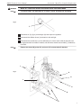
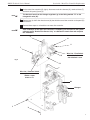
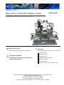
On the mass flow controller (R), (fig.6), disconnect main wire harness (S), nozzle air hose (T)
and the 2 air inputs (U) and (V).
The black air hose from the nitrogen regulators go to the fitting marked “R” on the
nitrogen/air valve (W).
13
Remove two (2) 3/32” allen head screws (Q) that hold the mass flow controller to the panel (R)
and remove.
14
Reverse these steps to re-install the new mass flow controller.
After installation of the mass flow controller is complete, you will need run the system
software profile “Nozzle Flow Sensor Only” to calibrate the nozzle flow and complete
the installation.
☛
S
U
V
R
T
P
W
Wire List - Flow Switch
#250 white/red = n.o.
#79 white/red = com.
Fig. 6
R
Wire List - Pressure Switch
yellow = com.
middle = open
brown = n.c.
Air
Nitrogen
Y
X
5