1
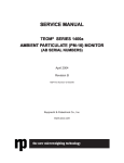
TEOM QA/SOP 2.27.1
Revision 3
5 /25 /06
page 1 of 14
Section I : Electronics and Calibration Branch
INSTALLATION AND MAINTENANCE
RESPONSIBILITIES FOR THE
TEOM CONTINUOUS PM 2.5 and PM 10
MONITORS
STANDARD OPERATING PROCEDURE
AND QUALITY ASSURANCE PLAN
Rupprecht & Patashnick
TEOM Series 1400a
Continuous Ambient Particulate PM-10 & PM-2.5 Monitor
Procedure for Operating a Rupprecht & Patashnick TEOM Series 1400a
PM-10 / PM-2.5 Continuous Ambient Particulate Monitor
TEOM QA/SOP 2.27.1
Revision 3
5 /25 /06
page 2 of 14
Table of Contents
Section
2.27.1.1 TEOM Installation and Maintenance
2.27.1.1.1 Set Up
2.27.1.1.2 Main Flow Connections
2.27.1.1.3 Auxiliary/Bypass Flow Connections
2.27.1.2 Operational Setup and Startup of TEOM
2.27.1.2.1
2.27.1.2.2
2.27.1.2.3
2.27.1.2.4
•
•
•
•
•
PM-2.5 Settings
PM-10 Settings
Setting for both PM-2.5 and PM-10
Calibration
Temperature and Pressure
Analog Board
Mass Flow Controller – Hardware / Software
Amplifier Board
Mass Transducer Verification/Calibration
2.27.1.3 Site Support
2.27.1.3.1 Preventative Maintenance
• In Line Filter Replacement And Mass Flow Controller
• Cleaning Sample Tubing and Heated Air Inlet
2.27.1.3.2
•
•
•
•
•
•
Periodic Calibrations
Temperature and Pressure
Analog Board
Amplifier Board
Mass Flow Controller – Hardware
Mass Flow Controller – Software
Mass Transducer Calibration/Calibration
TEOM QA/SOP 2.27.1
Revision 3
5 /25 /06
page 3 of 14
2.27.1.1
TEOM Installation and Maintenance (PM2.5 and PM10)
Rupprecht & Patashnick Manuals referred to for the operation and service of the TEOM
instrument:
1400a Operation Manual – Revision B.002, March 2002
1400a Service Manual – Revision B.006, April 2004
2.27.1.1.1 Set Up
There are two possible ‘set-ups’ for the TEOM instruments. One is for an “indoor”
installation, where the unit is installed in a walk-in building or trailer; the other is for a
“stand alone” all-weather cabinet-type enclosure.
For an “indoor” TEOM Series 1400a monitor installation begins with the positioning of
the control and sensor units. The TEOM units will be operated inside a room that is
temperature controlled and has 115 VAC power. The site room temperature is to be
controlled between 20 to 30 degrees Celsius, in order to reduce moisture buildup in the
main and auxiliary flow rate tubing. Water will damage mass flow controllers and
produce artificial data. A sturdy table or rack that will reduce shock and vibrations to the
sensor unit is to be used to support the sensor and control units. The TEOM sensor unit
should be positioned in a straight line directly below the rooftop, inlet assembly.
Determine the exact position of the sensor inlet unit that houses the filter/tapered element
assembly. Drill a 1-½ inch diameter hole in the roof directly over the sensor inlet port. A
roof flange supplied with the hardware components is used to seal this hole. Make sure
that the sensor inlet port is capped during installation activities to prevent material from
falling into the port. Drill a second hole, 1 inch in diameter, about 8 inches from the first
hole. This hole will be used to route the auxiliary flow tubing and ambient temperature
signal cable through the roof.
[Refer to section 2 “Hardware Installation” and figures 1-2; and 2-1 in the R&P TEOM
Series 1400a operator’s manual for more information about installation of a TEOM unit.]
The control unit’s electrical power must be set to 115 VAC. The R&P TEOM Series
1400a operator’s manual (section 2.3, figures 2-2 and 2-3) describes this operation in
detail. Each site configuration will determine where the control and sensor units are to be
placed and how the associated tubing is connected. The auxiliary flow tubing is
connected later to the PM-10/PM-2.5 inlet.
For a “stand alone” enclosure, installation begins with securing the instrument cabinet on
a level, stable platform. After the enclosure is put in place, power (and a phone line in
applicable locations) is run to the unit and the hardware is placed in the cabinet racks.
The sampling tube, inlet head, flow splitter, and sharp cut cyclone are all supported by
the cabinet rather than a tripod assembly. [Refer to section 2 “Hardware Installation” and
TEOM QA/SOP 2.27.1
Revision 3
5 /25 /06
page 4 of 14
Appendix K in the R&P TEOM Series 1400a operator’s manual for descriptions of the
stand alone cabinet installation of a TEOM unit.] In addition to the R&P supplied
hardware, cabling to plug directly into an operator’s laptop form the site data logger
should be provided (the ESC software will need to be installed on the laptop as well).
2.27.1.1.2 Main Flow Connections
Begin by assembling the flow splitter assembly. Adjust the inner tubing of the flow
splitter by loosening the nut holding the sample tubing. The tubing end is adjusted to be
15 centimeters (~6 inches) from the inlet end of the flow splitter (figure 2.37).
If a flow adaptor is installed, it will be necessary to slide the flow splitter down the
outlet tube; place the flow reducer nozzle on the exposed end of the outlet tube;
then reposition the flow splitter such that the end of the adapter/reducer is
approximately 6” below the top of the splitter. This will have the effect of raising
the inlet above its “non-adapted” height.
Tighten the nut again to secure the tubing. Be careful not to crimp the inner tube by over
tightening the nut. Set up the tripod assembly on the roof directly above the larger (1½
inch) hole. Insert the flow splitter into the support tripod and tighten the set-screws.
Adjust the tripod legs until the open end of the flow splitter is 1.5 to 1.8 meters (roughly
5-6 feet) above the roof. Insert a piece of ⅜-inch stainless steel tubing through the
opening in the roof flange. Connect the upper end of the tubing to base of the flow
splitter using a tubing connector. Check the lower end of the tubing inside the room for
correct length. If needed, add another piece of tubing and use another tube connector to
make the connection. The end of the tubing should be ½-inch or less from the top of the
sensor unit’s inlet port. Center the sensor unit directly under the sample tubing. The
flow splitter and the sample tubing should be in a vertically straight line with the sensor
unit’s inlet port. Install the three tripod foot mounts and secure to the tripod legs using
the rubber straps. Fasten the foot mounts to the roof using wood screws. Seal these
screws with a sealant to prevent water leaking into roof. A flexible rubber tube coupling
is suggested by R&P to connect the end of the stainless steel sample tubing from the
tripod, to the sensor inlet port. This coupling allows for some minor alignment errors.
A piece of ¼-inch tubing is connected to the sensor unit outlet port, and runs to the
control unit. A ¼ to ⅜-inch reducer fitting is used to connect to an inline filter. These
connections should be made with compression tubing fittings rather than the quickconnect fittings supplied by R&P whenever possible. If the quick connects are used,
insert the plastic tubing into the quick connect fitting and pulling out to lock it in place.
The other end of ¼ inch tubing is inserted into the ¼ inch reducer and tightened.
Connect the 3/8-inch reducer end to the inline filter and tighten. Use a ⅜-inch stainless
steel connector to connect the filter outlet to the main flow connection on the back of the
control unit.
[Refer to section 2.4 of the R&P TEOM operator’s manual for more information on the
installation of the flow components]
TEOM QA/SOP 2.27.1
Revision 3
5 /25 /06
page 5 of 14
2.27.1.1.3 Auxiliary/Bypass Flow Connections
The ⅜-inch plastic auxiliary flow tubing and the temperature sensor and cable are routed
from inside the room through the 1-inch roof hole. The auxiliary tubing and the
temperature sensor and cable are then pushed through a 1-inch PVC flanged floor mount.
Along with a 1-inch male threaded connector and two 1 inch 90 degree elbows, these
pieces provide a weatherproof roof entrance for the tubing and temperature cable. See
the diagram labeled “Auxiliary Roof Mount” below for guidance in fabrication. The
auxiliary tubing is then connected to the flow splitter bypass outlet using a stainless steel
fitting. The temperature sensor is installed in the temperature probe shield mounted on
the splitter. Following the diagram “Auxiliary Roof Mount” the roof mount can be
assembled and all excess tubing and cable can be fed back into the building. Do not
crimp the tubing or cable and leave a smooth curve in the tubing and cable.
Remove the quick connector for the auxiliary flow ports on the control unit and replace
with a stainless steel elbow fitting if possible. The elbow fitting will be easier to work
with and is less likely to have leaks. Measure a length of auxiliary tubing so an inline
filter can be installed with the filter outlet pointed up. To help prevent water from being
drawn from the filter into the mass flow controller, the tubing can be shaped like a “J “ to
facilitate the orientation. Stainless steel fittings are used to connect the ⅜-inch tubing to
the inline filter’s inlet and outlet. Use another piece of ⅜-inch tubing to make the
connection from the filter outlet, to the auxiliary flow connection located on the back of
the control unit. Make sure all fittings are tight.
Auxiliary Tubing and Temperature Cable Roof Mount
TEOM QA/SOP 2.27.1
Revision 3
5 /25 /06
page 6 of 14
After the roof mount installation is completed, the PM-10 inlet mast is installed by
slipping the exhaust port down over the flow splitter. For PM-2.5 TEOM’s, the PM-2.5
sharp cut cyclone is installed over the flow splitter, then installing the PM-10 inlet down
over the PM-2.5 impactor head. Internal “O” rings inside the both the PM-10 port and
PM-2.5 sharp cut cyclone seal the connection(s). The exterior temperature sensor cable
that runs from the roof, is connected to the temperature port located on the rear of the
control unit.
2.27.1.2
Operational Setup and Startup of TEOM
The Projects and Procedures Branch (PPB) staff will assist in the installation of TEOM
units by the Electronic and Calibrations Branch when needed. When the TEOM
subsystems have been linked together, the TEOM is ready to be turned on by pressing the
power button. The display screen will light up and the TEOM will go through a software
self testing procedure. After this test is complete, the main screen will appear. Plug in the
vacuum pump to start drawing the sample stream through the system. The main screen
will display status conditions flags for various parameters until they become stable at
their set points. When the temperatures and flow rates become stable several parameters
in the TEOM software program must be edited and verified.
2.27.1.2.1 PM-2.5 Settings.
For PM-2.5, follow this section. For PM-10, see ”PM-10 Settings” below (section
2.27.2.2). The PM-2.5 set-up requires software version 3.018 (as of 09/2005) to be
downloaded to the control unit. This software allows the PM-2.5 data to be calculated as
actual conditions and not EPA S.T.P. conditions. To download this software to the
TEOM control unit follow the guidelines given in the Rupprecht & Patashnick TEOM
series 1400a operator’s manual section appendix D. The PC communication port must be
set for 9600-baud rate. The 3.018 software download will clear the system memory.
Therefore, all the setup parameters must be re-edited. These software parameters are
used to control the operations and produce the data values. First, to be edited for the PM2.5 is the Set Temps/Flows Screen. Follow the guidelines given in the Rupprecht &
Patashnick TEOM series 1400a operator’s manual section 5.1 (Programming the
Monitor) or section 6.3.3 (Reporting to Actual Conditions) and make the needed changes.
In the Set Temps/Flows Screen:
• the line T-A/S is edited from 25.00 and 25.00 to 99.00 and 99.00
• the line P-A/S is edited from 1.00 and 1.00 to 9.00 and 9.00
2.27.1.2.2 PM-10 Settings.
The vendor has already installed the software needed for PM-10 at the factory. For the
PM-10 setup, the Set Temps/Flows Screen needs edited. Follow the guidelines given in
the Rupprecht & Patashnick TEOM series 1400a operator’s manual section 6.3.4
(Reporting to Standard Conditions) and make the needed changes.
TEOM QA/SOP 2.27.1
Revision 3
5 /25 /06
page 7 of 14
In the Set Temps/Flows Screen the line:
• the line T-A/S must be 25.00 and 25.00
• the line P-A/S must be 1.00 and 1.00
This setup allows the PM-10 data to be calculated as EPA S.T.P. conditions.
2.27.1.2.3 Setting for both PM-2.5 and PM-10.
Go to the SET Hardware Screen and follow the guidelines given in the Rupprecht &
Patashnick TEOM series 1400a operator’s manual sections 5.1 or section 6.4 to set the
needed hardware changes. Verify the calibration constant value matches the value of
the label located inside the mass transducer. The XX-Hr MC setting is a user settable
averaging interval in addition to the 30-min, 1-Hr, and 24-Hr settings observable in the
<main screen>, it can be set to 8 (hours). Several lines further down the <Set Hardware>
screen, verify the Const A equals 3.00, and Const B equals 1.030. These are empirically
set by R&P and are the initial settings. DMSSB will provide updated, site-specific values
to the operating region after four full quarters of operation. Go to the Set Time Screen
and follow the guidelines given in the R&P TEOM series 1400a operator’s manual
section 6.2 (Set Time Screen) and set the time. The time for the TEOM must be within 1
minute of the site data logger. Go to the <Set Storage Screen> and view the TEOM
variables listing that are being stored in memory (R&P Manual - section 6.5). The first 8
lines contain titles of the variables being stored. Variables that are to be listed are:
•
•
•
•
•
•
•
•
mass concentration,
30-minute mass concentration,
01-hour mass concentration,
24-hour mass concentration,
total mass,
main flow,
auxiliary flow, and
air temp.
If these variables are not listed, they need to be entered. Use the keypad editing
keystrokes and enter the program register code found in appendix A of the Rupprecht &
Patashnick TEOM series 1400a operator’s manual for these variables. The program
register codes are a 3-digit number that the software uses to identify variables that are
stored in memory.
The TEOM has 3 analog output channels that are used to transfer any TEOM variable to
a data logger for recording. The TEOM variables that are assigned to these variables will
be; 1-hour mass concentration, main flow, and filter loading. Channel 1 also is a status
watch indicator. In this mode, the analog signal output for channel 1 goes to full scale
when any status condition is out of limits. This flagging serves as a data editing and site
operation’s evaluation tool. The main flow and filter loading values are also used as
evaluation tools. When the data logger is polled, these channels give valuable
information on the current TEOM operations. To setup the analog outputs follow the
TEOM QA/SOP 2.27.1
Revision 3
5 /25 /06
page 8 of 14
steps given below and in the R&P TEOM series 1400a operators manual, section 9 and
appendix A.
Following the instructions in section 9.1 of the R&P TEOM series 1400a operator’s
manual, verify that the analog output jumpers are set to the 10 V setting. If changes are
needed turn the TEOM power off and then, change the jumper settings (see section 9.2.2
“Changing Analog Input and Output Jumpers” for further details). Using Section 9.2.1
(Set Analog Outputs) of the R&P manual, verify the analog outputs. Variable A01 is
main flow, variable A02 is 1-hour mass concentration, and variable A03 is filter loading.
Variable A01 min value is 0.0 and the max value is 5.00. Variable A02 min value is 0.0
and the max value is 500.0. Variable A03 min value is 0.0 and the max value is 100.0.
Following the instructions in section 9.1.1 of the R&P TEOM operator’s manual, the
current input values can be viewed in the <View Analog Input Screen>. A/I 0 through
A/I 6 are “un-editable” values assigned program register codes viewable in appendix B of
the R&P manual.
This should complete the analog setup. The TEOM setup at this point has all the
subsystems connected together and operating. The TEOM operating parameters should
be reviewed on the main screen to see if they are within operating specifications to verify
that the subsystems are working correctly. If any operating parameters are abnormal they
must be investigated and corrected.
2.27.1.2.4 Calibration
Once the subsystems and components are operating correctly and the settings have been
verified, if needed (and as designated by maintenance schedules) the components can be
calibrated following the calibration steps given in the Rupprecht & Patashnick TEOM,
series 1400a Service Manual – Revision B.002, March 2002 (section 3.2).
1) Calibrate the temperature and barometric pressure calibration should be
accomplished before flow calibrations are attempted, since the TEOM uses these values
to compute flow.
Calibration of the ambient temperature sensor is done annually using a precision
temperature-measuring device accurate to 0.1 degree Celsius. Open the top of the control
unit and then select the <Set Temps/Flows screen>. Follow the procedures given in
section 3.2.3 of the Rupprecht & Patashnick TEOM series 1400a service manual. Do not
expose the temperature measuring devices to direct sunlight or an area where the
temperatures can change rapidly during the calibration.
Calibration of the ambient barometric pressure is done annually using a precision
barometric measuring device accurate to 0.010 atmospheres. Open the top of the control
unit and select the <Set Temps/Flows screen>. Follow the procedures given in section
3.2.4 of the Rupprecht & Patashnick TEOM series 1400a service manual. Enter all data
on the Ambient Temperature and Pressure calibration and verification form (appendix-6).
TEOM QA/SOP 2.27.1
Revision 3
5 /25 /06
page 9 of 14
2a) Calibrate the analog board, following the procedures in the Rupprecht & Patashnick
TEOM series 1400a-service manual section 3.2.1. The TEOM analog output calibration
and amplifier board calibration are performed annually. A calibrated digital Multimeter
will be used to monitor the output voltages. Care must be exercised when unplugging
and reconnecting the ribbon cables to prevent bending the pins.
2b) Tune the amplifier board to verify that the proper voltages are present following the
procedures in section 3.2.2 of the Rupprecht & Patashnick TEOM Series 1400a-Service
Manual. Enter all data on the TEOM Analog output and Amplifier board Calibration
form. (See appendix number 7 in the appendix set)
3) Calibrating the mass flow controller is dependant on the age and/or current status of
the individual TEOM unit. Two different generation flow controllers were used by R&P,
with slightly different maintenance techniques and procedures. Units with serial numbers
of 140AB234170011 and less, contain the “first generation” MFC’s. Units with serial
numbers higher than 140AB234170011 are “second generation” MFC units. Refer to the
R&P Service Manual for the detailed instructions and differences between the two. The
general procedures are listed below:
Generation One units
• Clean MFC orifice
• Clean the MFC
• Calibrate the Software
• Calibrate the Hardware
Generation Two units
• Calibrate the Software
• Calibrate the Hardware
Calibration and maintenance of the mass flow controller hardware. For both
generations of flow controllers, follow the appropriate procedures in the Rupprecht &
Patashnick TEOM series 1400a-Service Manual, sections 3.4.5 and 3.5.2. Calibration of
the flow controllers is a two-part procedure. For both versions, a reference flow meter
calibrated to a primary standard and having an accuracy of 1% at 3 liters per minute is
required to measure the flow rates. ECB personnel use a dry piston type calibrator
manufactured by BIOS to calibrate the TEOM flow controllers. This device requires a
30-minute equilibration period to acclimate the piston and cylinder volume to the site
temperature. The mass flow controller hardware must be calibrated annually. This
procedure calibrates the hardware that controls the mass flow controllers and sets the
mass flow controller’s flow rates to a slope factor of 1.000.
Calibrate the mass flow controller software for each version of MFC following the
applicable procedures in the Rupprecht & Patashnick TEOM Series 1400a-Service
Manual, section 3.4.5 and 3.5.1. The mass flow controller software calibration is done
TEOM QA/SOP 2.27.1
Revision 3
5 /25 /06
page 10 of 14
every 6 months. This procedure allows the sample and bypass flow rates to be calibrated
without adjusting the hardware. All TEOM flow rates are volumetric and are read as
actual conditions. All flow rate readings must be read as actual volume. Depending on
the type of reference flow meter used, the flow rate may require correcting from a mass
flow rate to the actual conditions. Enter all calibration data on the TEOM flow rate
calibration form. (See appendix number 8 in the appendix set)
4) The last item is the mass transducer calibration verification. This task requires
having laboratory personnel pre-weigh a sample filter following the procedures listed in
the “Headquarters Responsibilities” section under “Laboratory Ambient Monitoring
Branch Responsibilities and Assignments” portion of this QA/SOP. The actual
verification procedure is in the “Site Operators” section (under “Verification and
Calibration of Mass Transducer”), and is also detailed in both the R&P Operator’s
Manual (section 12.2.1) and the Rupprecht & Patashnick TEOM Series 1400a-Service
Manual (section 3.2.5). (See appendix number 9 “KO Verification” in the appendix set)
All of the above calibrations and verifications are to be documented using the appropriate
forms found in the appendix and the site logbook. This documentation will be kept in a
file at Headquarters and a copy will be kept at the regional office for the site operators.
2.27.1.3
Site Support
A data logger will be maintained at all sites to process the TEOM analog outputs. This
TEOM data is to be downloaded along with other site parameters for data processing and
review. The data logger requires three analog input channels for each TEOM unit. The
PC is used to access the data logger to review data, or change operating parameters. The
data logger is setup with a modem to provide remote access to the site. The Electronic
Calibration Branch will maintain, provide replacements and service to these components
when needed.
Site maintenance for the air conditioning, heating, telecommunications and electrical
power will be done in a timely manner to prevent loss of data and damage to instruments.
The Electronic Calibration Branch will maintain, provide replacements and service to
these components when needed.
The regular maintenance and calibration tasks for the TEOM instrument are shared by
both the operating Region and the ECB. The table below lists the tasks, the time frames,
and the responsibility for each.
TEOM QA/SOP 2.27.1
Revision 3
5 /25 /06
page 11 of 14
Maintenance Procedures
Interval
Service Manual
Reference
Duty
Maintenance of the R&P PM-10 inlets
Maintenance of the R&P PM-2.5 inlets
Exchanging the large bypass in-line filters
Testing the batteries–exchange if necessary
Pump test
Cleaning the air inlet system
Exchanging fuses
Clock adjustment procedure
Resetting the system
Downloading system software
Rebuilding the piston pump
@ filter xchng
@ filter xchng
6 months
6 months
6 months
1 year
As needed
As needed
As needed
As needed
18 months
Section 3.1.1
Section 3.1.2
Section 3.1.3
Section 3.1.4
Section 3.1.5
Section 3.1.6
Section 3.1.7
Section 3.1.8
Section 3.1.9
Section 3.1.10
In rebuild kit
Reg.
Reg.
ECB
ECB
ECB
ECB
Both
Both
Both
ECB
ECB
1 year
1 year
1 year
1 year
1 year
Section 3.2.1
Section 3.2.2
Section 3.2.3
Section 3.2.4
Section 3.2.5
ECB
ECB
ECB
ECB
ECB
CALIBRATION PROCEDURES
Analog I/O calibration
Amplifier board calibration
Ambient air temperature calibration
Ambient pressure calibration
Mass transducer calibration verification
FIRST-Generation
FLOW CONTROLLERS
Exchanging flow controller filters
Cleaning flow controller orifices
Cleaning flow controller block / valves
Flow controller calibration (Hardware)
Flow controller calibration (Software)
Removing/replacing the mass flow
controllers
Yearly or as
needed
1 year
Section 3.4.1
ECB
Section 3.4.2
1 year
1 year
6 months
Section 3.4.3
Section 3.4.5
Section 3.4.4
ECB
ECB
ECB
ECB
As needed
Section 3.4.6
ECB
6 months
1 year
Section 3.5.1
Section 3.5.2
ECB
ECB
As needed
Section 3.5.3
ECB
SECOND-Generation
FLOW CONTROLLERS
Flow controller calibration (Software)
Flow controller calibration (Hardware)
Removing/replacing the mass flow
controllers
All TEOM site visits and maintenance assignments will be documented in the site
logbook to support the TEOM quality assurance requirements. Site visits should also be
recorded in the appropriate electronic logs when appropriate (audits and calibrations).
The site logbook is the official TEOM documentation of site activities and operations.
This logbook is to be kept on site at all times to provide field operators and headquarters
staff of operational history and operating status.
TEOM QA/SOP 2.27.1
Revision 3
5 /25 /06
page 12 of 14
Before performing major maintenance or repair work, the TEOM unit’s data
must be downloaded, as a precaution against unintentionally losing data that the
region has not yet retrieved.
2.27.1.3.1
Preventative Maintenance
Preventative maintenance tasks are required to insure quality data collection and the
reliability of TEOM operations.
1) In Line Filter Replacement And Mass Flow Controller Cleaning
Replace the inline filters on the auxiliary and main flow lines every 6 months. Follow the
procedures in section 3.1.3 of the Rupprecht & Patashnick TEOM Series 1400a-Service
Manual.
The first generation flow controllers (serial numbers of 140AB234170011 and less)
require cleaning and their filters replaced annually. Follow the procedures in section 3.4
of the Rupprecht & Patashnick TEOM Series 1400a-Service Manual. After cleaning the
mass flow controllers they should be calibrated following the steps above.
2) Cleaning Sample Tubing and Heated Air Inlet
Cleaning of the sample tubing and the heated air inlet is required on an annual basis.
Follow the procedures given in the Rupprecht & Patashnick TEOM series 1400a
Operator’s Manual section 12.1.2, or section 3.1.6 of the Rupprecht & Patashnick TEOM
series 1400a Service Manual. The objective is to remove the matter attached to the
tubing walls. Be sure to rinse the tubing with clean water and let it dry.
2.27.1.3.2
Periodic Calibration
Temperature and Barometric Pressure Calibration
Calibration of the ambient temperature sensor is done annually using a precision
temperature-measuring device accurate to 0.1 degree Celsius. Both temperature and
barometric pressure calibration should be accomplished before flow calibrations are
attempted, since the TEOM uses these values to compute flow. Open the top of the
control unit and the select the <Set Temps/Flows screen>. Follow the procedures given
in section 3.2.3 of the Rupprecht & Patashnick TEOM series 1400a service manual. Do
not expose the temperature measuring devices to direct sunlight or an area where the
temperatures can change rapidly during the calibration. Note: The unit of measure used
to calculate flow is Kelvin degrees, so a large variation (30 deg or more) is needed to
adversely effect the flow calculation.
TEOM QA/SOP 2.27.1
Revision 3
5 /25 /06
page 13 of 14
Calibration of the ambient barometric pressure is done annually using a precision
barometric measuring device accurate to 0.010 atmospheres. Open the top of the control
unit and select the <Set Temps/Flows screen>. Follow the procedures given in section
3.2.4 of the Rupprecht & Patashnick TEOM series 1400a service manual. Enter all data
on the Ambient Temperature and Pressure calibration and Verification form. (See
appendix number 6 in the appendix set)
Analog Board
The TEOM analog output calibration and amplifier board calibration are performed
annually. Follow the procedures in the Rupprecht & Patashnick TEOM series 1400aservice manual section 3.2.1. A calibrated digital Multimeter will be used to monitor the
output voltages. Care must be exercised when unplugging and reconnecting the ribbon
cables to prevent bending the pins. Enter all data on the TEOM analog output and
amplifier board calibration form. (See appendix number 7 in the appendix set)
Amplifier Board
Tune the amplifier board to verify that the proper voltages are present following the
procedures in section 3.2.2 of the Rupprecht & Patashnick TEOM Series 1400a-Service
Manual. The amplifier board should be tuned annually. (See appendix number 7 in the
appendix set)
Flow Controller Calibration
Calibrating the mass flow controller is dependant on the age and/or current status of the
individual TEOM unit. Two different generation flow controllers were used by R&P,
with slightly different maintenance techniques and procedures. Units with serial numbers
of 140AB234170011 and lower, contain the “first generation” MFC’s. Units with serial
numbers higher than 140AB234170011 are “second generation” MFC units. Refer to the
R&P Service Manual for the detailed instructions and differences between the two. The
general procedures are listed below:
Generation One units
• Clean MFC orifice
• Clean the MFC
• Calibrate the Software
• Calibrate the Hardware
Generation Two units
• Calibrate the Software
• Calibrate the Hardware
Calibration and maintenance of the mass flow controller hardware. For both
generations of flow controllers, follow the appropriate procedures in the Rupprecht &
TEOM QA/SOP 2.27.1
Revision 3
5 /25 /06
page 14 of 14
Patashnick TEOM series 1400a-Service Manual, sections 3.4.5 and 3.5.2. Calibration of
the flow controllers is a two-part procedure. For both versions, a reference flow meter
calibrated to a primary standard and having an accuracy of 1% at 3 liters per minute is
required to measure the flow rates. ECB personnel use a dry piston type calibrator
manufactured by BIOS to calibrate the TEOM flow controllers. This device requires a
30-minute equilibration period to acclimate the piston and cylinder volume to the site
temperature. The mass flow controller hardware must be calibrated annually. This
procedure calibrates the hardware that controls the mass flow controllers and sets the
mass flow controller’s flow rates to a slope factor of 1.000.
Calibrate the mass flow controller software for each version of MFC following the
applicable procedures in the Rupprecht & Patashnick TEOM Series 1400a-Service
Manual, section 3.4.5 and 3.5.1. The mass flow controller software calibration is done
every 6 months. This procedure allows the sample and bypass flow rates to be calibrated
without adjusting the hardware. All TEOM flow rates are volumetric and are read as
actual conditions. Depending on the type of reference flow meter used, all flow rate
readings must be read as actual volume. Some types of flow meters may require
correcting the flow rates from a mass flow rate to the actual conditions. Enter all
calibration data on the TEOM flow rate calibration form. (See appendix number 8 in the
appendix set)
Verification and Calibration of Mass Transducer
The last item is the mass transducer calibration verification. The transducer should be
verified annually. This task requires having laboratory personnel pre-weigh a sample
filter following the procedures listed in the “Headquarters Responsibilities” section under
“Laboratory Ambient Monitoring Branch Responsibilities and Assignments” portion of
this QA/SOP. The actual verification procedure is in the “Site Operators” section (under
“Verification and Calibration of Mass Transducer”), and is also detailed in both the R&P
Operator’s Manual (section 12.2.1) and the Rupprecht & Patashnick TEOM Series
1400a-Service Manual (section 3.2.5). This procedure is done to confirm that the mass
transducer’s mechanical properties are working properly and that the calibration is within
limits of +/- 2.5%. (See appendix number 9 in the appendix set)
All of the above calibrations and verifications are to be documented using the appropriate
forms found in the appendix and the site logbook. This documentation will be kept in a
file at Headquarters and a copy will be kept at the regional office for the site operators.
TEOM appendix QA/SOP 2.27
10/28/05
Appendix for TEOM
ECB
STANDARD OPERATING PROCEDURE
AND QUALITY ASSURANCE PLAN
Rupprecht & Patashnick
TEOM Series 1400a / ab
Continuous Ambient Particulate PM-10 & PM-2.5 Monitor
Procedure for Operating Rupprecht & Patashnick TEOM Series 1400a
PM-10 / PM-2.5 Continuous Ambient Particulate Monitor
TEOM appendix QA/SOP 2.27
10/28/05
TEOM Ambient TEMPERATURE and PRESSURE Calbr/Verfn
Site: _________________
Date: ________________
Time: ________________
Operator: ______________
TEOM Instrument S/N: ______________
TEMPERATURE ( + / - 2 deg C )
Calibration/Verification Device: _____________
Calibration/Verification S/N: ______________
Calibration/Verification Calibrated: ______________
TEOM Reading
DEVICE Reading
TEOM Reading
DEVICE Reading
Temperature (deg C)
Temperature (deg C)
PRESSURE ( + / - 10 mm Hg, or 0.013 atm )
Calibration/Verification Device: _____________
Calibration/Verification S/N: ______________
Calibration/Verification Calibrated: ______________
TEOM Reading
DEVICE Reading
TEOM Reading
DEVICE Reading
Pressure (atm)
Pressure (atm)
NOTES:
App-6. .Temp-Press
TEOM appendix QA/SOP 2.27
10/28/05
TEOM ANALOG Calibration
Site: _________________
Date: ________________
Time: ________________
Operator: ______________
TEOM Instrument S/N: ______________
Multimeter Model : ______________
Multimeter S/N: ______________
ANALOG OUTPUT Calibration
Output Channel
1
2
3
4
5
6
Input Range
90%
90%
90%
90%
90%
90%
Multimeter VDC
BEFORE Adj.
AFTER Adj.
AMPLIFIER BOARD Calibration
Test Point
TP0 VDC
TP0 Vrms
TP1 Vrms
TP2 Vrms
TP3 Vrms
TP4 VDC
TP5 Vrms
BEFORE Adj.
Expected Value Multimeter reading
-4.2
0.2 (oscill.scope
0.5 v peak-peak
3.0 (9 v p-p)
7.0 (20 v p-p)
0.2-0.8
(0.6-1.5 v p-p)
3.0 (9 v p-p)
8.0 (16 v p-p)
AFTER Adj.
Value
Multimeter reading
CPU Battery Check : _____________
NOTES:
App-7-Analog
TEOM appendix QA/SOP 2.27
10/28/05
TEOM MASS FLOW CONTROLLER Hardware/Software
Site: _________________
Date: ________________
Time: ________________
Operator: ______________
TEOM Instrument S/N: ______________
Ambient Temp: _______________
Ambient Pressure: _____________
HARDWARE Verification and Calibration
Controller Check Card
10 vDC +/- 0.001
Calibration Device Type: ______________
Calibration Device S/N: _______________
Cal. Device Calibrated: _______________
BEFORE
Adjusted to:
Main Q
Aux Q
BEFORE
TEOM Reading
Calibrator Reading
Slope
Difference
TEOM Reading
Calibrator Reading
Slope
Difference
MAIN Flow – low
MAIN Flow – high
AUX Flow – low
AUX Flow – high
AFTER
MAIN Flow – low
MAIN Flow – high
AUX Flow – low
AUX Flow – high
SOFTWARE Verification and Calibration
Calibration Device Type: ______________
_______________
Calibration Device S/N:
Cal. Device Calibrated: _______________
BEFORE
TEOM Reading
Calibrator Reading
Slope
Difference
TEOM Reading
Calibrator Reading
Slope
Difference
MAIN Flow
AUX Flow
AFTER
MAIN Flow
AUX Flow
App-8-MFC
TEOM appendix QA/SOP 2.27
10/28/05
TEOM K0 Verification
Site: _________________
Date: ________________
Time: ________________
Operator: ______________
TEOM Instrument S/N: ______________
K0 Confirmation Screen
K0 Confirm :
_______________
Filter Weight (g) : _____________
Frequency w/ NO Filter, f 0 : ______________
Frequency w/ Audit Filter, f 1 :
AUDIT K0 :
____________
Weight Determined
DATE : _____________
By : ____________
_______________
ACTUAL K0 :
Percent Difference ;
_______________
______________
NOTES:
App-9-K0