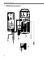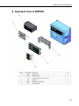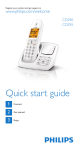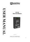
1
RDP500 Remote Data Platform
Revision: 8/10
C o p y r i g h t © 2 0 0 7 - 2 0 1 0
C a m p b e l l S c i e n t i f i c , I n c .
Warranty and Assistance
The RDP500 REMOTE DATA PLATFORM is warranted by Campbell
Scientific, Inc. to be free from defects in materials and workmanship under
normal use and service for twelve (12) months from date of shipment unless
specified otherwise. Batteries have no warranty. Campbell Scientific, Inc.'s
obligation under this warranty is limited to repairing or replacing (at Campbell
Scientific, Inc.'s option) defective products. The customer shall assume all
costs of removing, reinstalling, and shipping defective products to Campbell
Scientific, Inc. Campbell Scientific, Inc. will return such products by surface
carrier prepaid. This warranty shall not apply to any Campbell Scientific, Inc.
products which have been subjected to modification, misuse, neglect, accidents
of nature, or shipping damage. This warranty is in lieu of all other warranties,
expressed or implied, including warranties of merchantability or fitness for a
particular purpose. Campbell Scientific, Inc. is not liable for special, indirect,
incidental, or consequential damages.
Products may not be returned without prior authorization. The following
contact information is for US and International customers residing in countries
served by Campbell Scientific, Inc. directly. Affiliate companies handle
repairs for customers within their territories. Please visit
www.campbellsci.com to determine which Campbell Scientific company
serves your country.
To obtain a Returned Materials Authorization (RMA), contact Campbell
Scientific, Inc., phone (435) 753-2342. After an applications engineer
determines the nature of the problem, an RMA number will be issued. Please
write this number clearly on the outside of the shipping container. Campbell
Scientific's shipping address is:
CAMPBELL SCIENTIFIC, INC.
RMA#_____
815 West 1800 North
Logan, Utah 84321-1784
For all returns, the customer must fill out a “Declaration of Hazardous Material
and Decontamination” form and comply with the requirements specified in it.
The form is available from our website at www.campbellsci.com/repair. A
completed form must be either emailed to [email protected] or faxed to
435-750-9579. Campbell Scientific will not process any returns until we
receive this form. If the form is not received within three days of product
receipt or is incomplete, the product will be returned to the customer at the
customer’s expense. Campbell Scientific reserves the right to refuse service on
products that were exposed to contaminants that may cause health or safety
concerns for our employees.
RDP500 Remote Data Platform
Table of Contents
PDF viewers note: These page numbers refer to the printed version of this document. Use
the Adobe Acrobat® bookmarks tab for links to specific sections.
1. Introduction and Theory of Operation .......................1
2. Unpacking RDP500......................................................1
2.1 Parts List ...................................................................................................1
2.1.1 Common Accessories......................................................................2
3. Installation....................................................................2
3.1
3.2
3.3
3.4
Rain Gauge Preparation............................................................................2
Internal Enclosure and Load Cell .............................................................6
Solar Panel and Grounding Wire Installation Instructions .....................11
Overload Protection Adjustments...........................................................13
4. Calibration Instructions ............................................14
5. Software......................................................................17
5.1 PC200W Software ..................................................................................17
5.2 DevConfig ..............................................................................................18
5.2.1 Sending OS with DevConfig ........................................................19
6. CompactFlash® (CF) .................................................21
7. RDP500 Wiring Diagram............................................22
8. Exploded View of RDP500 ........................................23
Appendices
A. Example CRBasic Program.................................... A-1
B. Updating RDP500 Software .................................... B-1
B.1 Introduction..........................................................................................B-1
B.2 Update Process.....................................................................................B-1
B.2.1 Back Up the RDP500 – Step 1 ...................................................B-1
B.2.2 Send the Operating System – Step 2 ..........................................B-1
i
RDP500 Remote Data Platform Table of Contents
B.2.3 Send the CRBasic Program – Step 3 ......................................... B-2
B.2.4 Send the CD295/DataView II Configuration – Step 4 .............. B-2
B.3 Change Log ......................................................................................... B-3
C. Exchanging Internal Enclosure Mounting Bracket .C-1
C.1 Introduction ......................................................................................... C-1
C.2 Exchange Process................................................................................ C-1
Figures
3.1-1. Removal of the screws that hold on the pointer. ................................. 3
3.1-2. Releasing the tension spring................................................................ 3
3.1-3. Bolts that will be loosened to remove punch assembly and tape reel
assembly. ......................................................................................... 4
3.1-4. Adjustment of overload protection screw............................................ 4
3.1-5. Unscrewing zero adjustment knob. ..................................................... 5
3.1-6. Removal of helical spring.................................................................... 5
3.1-7. The parallelogram is stabilized with one hand while
the dashpot rod is unscrewed with the other.................................... 6
3.2-1. A gap of ~1/8” left under the bolt heads allows enclosure bracket to
slide under bolt head. ....................................................................... 7
3.2-2. Keyholes aligned over bolts. ............................................................... 7
3.2-3. Tightening bolts to attach enclosure to the base.................................. 8
3.2-4. Properly installed internal enclosure. .................................................. 9
3.2-5. Flat blade screwdriver turns the gain adjusting screw....................... 10
3.2-6. Side view showing cable and arms horizontal
and overload protection screw. ...................................................... 10
3.3-1. Solar panel cable and grounding wire routed through compression
fitting of rain gauge base. .............................................................. 12
3.3-2. Solar panel cable routed through compression fitting of internal
enclosure. ....................................................................................... 12
3.4-1. Calibration weights properly placed in the center of the basin. ........ 13
4-1. Default Campbell Scientific screen on a CR1000KD. ...................... 14
4-2. The Precip_in field displayed on a CR1000KD ................................ 15
4-3. The Initial Setup menu on the CR1000KD. ...................................... 15
4-4. The Cal Results table displayed on a CR1000KD............................. 16
5.1-1. PC200W Setup/Connect Tab............................................................. 18
5.2-1. DevConfig CR1000 Facility.............................................................. 19
5.2-2. DevConfig OS download window for CR1000. ............................... 20
5.2-3. Dialog Box Confirming a Successful OS Download ........................ 20
ii
RDP500 Remote Data Platform
1. Introduction and Theory of Operation
The RDP500 is a Remote Data Platform that provides a versatile measurement
system with data storage and control capabilities. When combined with the
load-cell option, it may be used to retrofit NWS Fischer-Porter rain gauges to
take unattended time-stamped readings.
This manual will walk you through the process of using an RDP500. To
accomplish this, you will need the RDP500 Remote Data Platform from
Campbell Scientific and the following tools:
Flat-head screwdriver (provided)
7/16 in. flat wrench (provided)
Dashpot rod removal tool (provided)
2. Unpacking RDP500
Verify that you have all of the equipment (see Section 2.1).
2.1 Parts List
To automate a Fischer Porter/Belfort weighing style rain gauge one of the Load
Cell options must be ordered. Option –SL p/n 21927 includes the standard
load cell configuration. Option –TL p/n 21928 includes the standard load cell
and PRT temperature sensor. Campbell Scientific does not use the PRT for
load cell temperature compensation. The load cell has proven to meet NWS
specs for the Fischer Porter weighing style rain gauge without temperature
compensation. The equipment included with the standard RDP500 system is
listed below.
(1) CR1000-XT-SW-NC
(1) CR1000 OR CR800 STACK MOUNTING KIT [p/n 17565]
(1) PS100-SW W/ 7 Ahr BATTERY
(1) CFM100-XT-SW
(2) CFMC64M COMPACT FLASH MEMORY CARD
(1) CD295 DATAVIEW II [p/n 18131]
(1) SP10 10 W SOLAR PANEL W/ 20ft CABLE & MOUNTING
HARDWARE
(1) 9-PIN FEMALE TO MALE SERIAL DATA CABLE [p/n 10873]
(1) WRENCH 7/16” THIN-HEAD [p/n 21924]
(3) DESICCANT ½ UNIT BAG [p/n 905]
(1) FLATHEAD SCREWDRIVER [p/n 1113]
(1) RDP500 ENCLOSURE FIBER GLASS 11.21 X 9.21 X 6.09 GRAY [p/n
21916]
1
RDP500 Remote Data Platform
(1) RDP500 ENCLOSURE MOUNTING BRACKET [p/n 21921]
(1) RDP500 ENCLOSURE BACK PANEL [p/n 21922]
(2) NUT ¼”-20 [p/n1132]
(4) HRD SCREW 5/16-18 X .750 CAP HEX SS [p/n 4364]
(4) HRD SCREW #10-32 X .375 PAN PHILLIPS [p/n 6950]
(4) HRD WASHER 5/16 FLAT [p/n 4365]
(1) HRD CABLE ENTRY SEAL .110 - .260 ID PG7 W/NUT [p/n 8913]
(2) HRD CABLE ENTRY SEAL .187 - .312 ID [p/n 5771]
(1) FAB ENC HEYCO CONNECTOR PLUG .250 DIA [p/n 6688]
(1) FAB ENC CASE GROUND LUG SINGLE CONNECTOR [p/n 5449]
(1) HRD CABLE ENTRY SEAL .187 - .312 ID NPT [p/n 14286]
(1) HRD FITTING PIPE HEX REDUCING BUSHING, 1/2 MNPT X 3/8
FNPT [p/n 21923]
(2) HRD NUT #10-32 [p/n 23]
(1) GROUND CABLE [p/n 5725]
SUB ENCLOSURE GROUND CONNECTION
2.1.1 Common Accessories
The CR1000KD is ordered as an accessory. This unit allows technicians to
perform installation and calibration functions, but may not be useful to onsite
personnel.
3. Installation
3.1 Rain Gauge Preparation
2
1.
Remove the upper hood of the rain gauge, empty and dry the bucket.
2.
Lift off the lower housing and disconnect the internal wiring along with
any clamps and terminal strips.
3.
Unscrew the two screws holding the pointer from the front arm of the
parallelogram (Figure 3.1-1).
RDP500 Remote Data Platform
Zero Adjustment Knob
Front Moving End of the
Parallelogram
FIGURE 3.1-1. Removal of the screws that hold on the pointer.
4.
Remove the screw holding the eyelet end of the steel cable from the front
movable member of the parallelogram and release the cable. The flexures
of the parallelogram mechanism can be damaged if the front arm is side
loaded or moved beyond the specified travel.
5.
Release the tension spring from the movable support arm (Figure 3.1-2).
Vertical Flexures
Horizontal Flexures
FIGURE 3.1-2. Releasing the tension spring.
3
RDP500 Remote Data Platform
6.
Take off the punch assembly and tape reel assembly (Figure 3.1-3).
FIGURE 3.1-3. Bolts that will be loosened to remove punch assembly
and tape reel assembly.
7.
Using the overload protection screw, lift the front arm assembly until the
parallelogram arms are horizontal (Figure 3.1-4).
Overload Protection Screw
FIGURE 3.1-4. Adjustment of overload protection screw.
4
RDP500 Remote Data Platform
8.
Unscrew the zero adjustment knob (Figure 3.1-5) until the two loadsupporting helical springs can be taken out (Figure 3.1-6).
FIGURE 3.1-5. Unscrewing zero adjustment knob.
FIGURE 3.1-6. Removal of helical spring.
9.
WARNING
Unscrew the rod of the dashpot from the front arm and let it rest on the
bottom of the reservoir (Figures 3.1-6 and 3.1-7).
The moving end of the parallelogram must be held in
place while unscrewing the rod, otherwise, the
parallelogram might be damaged.
5
RDP500 Remote Data Platform
Dashpot Rod Removal Tool
Dashpot Rod
FIGURE 3.1-7. The parallelogram is stabilized with one hand while
the dashpot rod is unscrewed with the other.
10. Clean the inside of the instrument.
11. Inspect all flexures (leaf springs). There are two pair—one horizontal and
one vertical at each fulcrum of the parallelogram (see Figure 3.1-2).
12. Replace the ones that are damaged (broken, bent, kinked or cracked).
13. Check if all screws holding the flexures are tight. The measurement
accuracy, resolution, and stability of the instrument depend on the
parallelogram mechanism being properly secured.
3.2 Internal Enclosure and Load Cell
6
1.
Unpack the enclosure, but leave the load cell taped to the top until the
enclosure is firmly attached to the base.
2.
Re-install the two bolts that held the punch mechanism, but remove all
washers. Do not tighten the two bolts at this point; leave a gap of
approximately 1/8” under the bolt head to allow clearance for the
enclosure bracket to slide freely under the bolt head (Figure 3.2-1).
RDP500 Remote Data Platform
Gap
Gap
FIGURE 3.2-1. A gap of ~1/8” left under the bolt heads allows
enclosure bracket to slide under bolt head.
3.
Install the enclosure assembly onto the base.
4.
Align the two keyholes in the bottom of the enclosure bracket over the two
bolts; then slide the enclosure to the right until the keyhole slots bottom
against the bolts (Figure 3.2.-2).
FIGURE 3.2-2. Keyholes aligned over bolts.
7
RDP500 Remote Data Platform
5.
NOTE
Using the small 7/16” wrench provided, tighten the two bolts to firmly
attach the enclosure to the base. The two bolts are easily accessed through
the slots on either side of the enclosure bracket (Figure 3.2-3 and 3.2-4).
Slight variability may exist among Fischer/Porter and Belfort
rain gauge bases. If the internal enclosure cannot be mounted so
that the rain gauge’s outer housing will not slide on, please
contact Campbell Scientific, Inc.
Thin Head Wrench
FIGURE 3.2-3. Tightening bolts to attach enclosure to the base.
8
RDP500 Remote Data Platform
FIGURE 3.2-4. Properly installed internal enclosure.
Notice it is slightly shifted to the right.
6.
Once the datalogger enclosure is firmly mounted, remove the load cell
from the top of the enclosure.
7.
Route the load cell from the backside of the support structure and suspend
it from the upper hook with the U-bolt bracket facing up.
8.
Using a flat blade screwdriver, turn the gain adjusting screw to move the
lower hook all the way inward—towards the fixed end of the
parallelogram (Figure 3.2-5).
9
RDP500 Remote Data Platform
Flat Blade Screwdriver
FIGURE 3.2-5. Flat blade screwdriver turns the gain adjusting screw.
9.
Lift the front member of the parallelogram carefully and route the lower
hook through the eyebolt and slowly lower the front-end parallelogram.
10. Use the upper hook adjusting nut to shorten the distance between the two
hooks so that the weight of the moving end of the parallelogram is
supported by the load cell (Figure 3.2-6).
FIGURE 3.2-6. Side view showing cable and arms horizontal
and overload protection screw.
10
RDP500 Remote Data Platform
For optimal operation, the arms of the parallelograms should be horizontal
and parallel to the base of the rain gauge. If the front end is too high,
lower the shipping bolt and unscrew the adjusting nut on the top hook. If
the front end is too low, then tighten the adjusting nut on the top hook.
11. Orient the U-bolt bracket so that it is perpendicular to the upper hook, the
eye bolt is perpendicular to the lower hook, and the load cell is parallel to
the arms of the parallelogram.
12. Check to see if the eyebolt is centered on the lower hook.
13. Strain relief the load cell cable with cable ties so that it comes straight and
horizontally from the load cell without applying any forces on it.
14. Power up the datalogger and look at the load cell readings on the CD295
data display while slightly pushing down on the front member of the
parallelogram. The reading “Precip_in” should increase when applying
vertical force and come back to its original value once the force is
removed.
3.3 Solar Panel and Grounding Wire Installation Instructions
The RDP500 includes a 10-watt solar panel, 15’ cable, and mounting hardware.
The user must supply a mounting pole (for attaching the solar panel)
compatible with U-bolts that have a 2.125" inside leg length and a 2.5"
centerline width.
The RDP500 is also outfitted with a grounding lug located on the outside of the
internal enclosure. The user must establish a good earth ground and route it to
the grounding lug to ensure proper operation.
1.
Thread the brass hex-reducing bushing into the threaded port recessed in
the rain gauge base.
11
RDP500 Remote Data Platform
2.
Feed the solar panel cable and grounding wire through the plastic
compression fitting and brass hex bushing into the base of the rain gauge
(Figure 3.3-1).
FIGURE 3.3-1. Solar panel cable and grounding wire routed through
compression fitting of rain gauge base.
3.
Route the solar panel cable through the compression fitting attached to the
internal enclosure and up into the PS100 charging source (Figure 3.3-2).
Grounding Wire
Load Cell Cable
Solar Panel Cable
FIGURE 3.3-2. Solar panel cable routed through compression fitting of
internal enclosure.
12
RDP500 Remote Data Platform
4.
Wire the red and black leads into the terminals labeled “charge” on the
PS100 (see wiring diagram at the end of the manual). The polarity of the
solar panel is not important.
5.
Route the grounding wire to the grounding lug and secure with screw
provided. The instruments located inside the internal enclosure are already
routed to the grounding lug from the factory.
3.4 Overload Protection Adjustments
1.
Install the catch basin tare in the instrument.
2.
Carefully place all of the available calibration weights in the basin—
around 20000 grams (Figure 3.4-1).
FIGURE 3.4-1. Calibration weights properly placed in the
center of the basin.
3.
If either load protection screw touches the front member of the
parallelogram, back them out until there is approximately 1/16 of an inch
distance (thickness of a penny) between the bottom of the front member
and the top end of the screw.
4.
Wait for the load cell readings to stabilize and make a note of it.
5.
Turn one of the shipping screws until it touches the bottom of the front
member by observing the corresponding change in the load cell reading.
6.
Back up the screw slowly until all the weight is supported by the load cell
and the reading returns to the previously noted value. This will ensure that
the load cell will be able to measure a full basin of water, but applying any
larger force will cause the parallelogram to bottom out on the load
protection screws thus protecting the load cell from overloading.
13
RDP500 Remote Data Platform
4. Calibration Instructions
A two-point calibration is adequate because the load cell is linear to within 2.5
grams (0.003” rain equivalent). This calibration procedure assumes the user
has a properly mounted, level, and fully functional RDP500 weighing style rain
gauge.
NOTE
1.
Begin by removing the top hood from the rain gauge and emptying,
drying, and cleaning out the rain gauge catch basin. Make sure proper
HAZMAT protocols are followed to dispose of the liquid in catch basins
containing oil or antifreeze.
2.
Open the exterior rain gauge access door and the internal enclosure door to
gain access to the datalogger.
3.
Insert the male end of the SC12 cable (provided) into the CS I/O port on
the wiring panel of the CR1000 datalogger and connect either female end
to the CR1000KD keyboard display module.
A standard serial cable may be substituted for the SC12 cable.
Once powered, the CR1000KD will light up and display the default
Campbell Scientific screen.
FIGURE 4-1. Default Campbell Scientific screen on a CR1000KD.
If the CR1000KD times out and the screen goes blank, simply press any
key to re-activate the keyboard display. The Esc key is used to navigate
backwards through the custom menu.
14
RDP500 Remote Data Platform
4.
Carefully reinstall the catch basin and wait for 5 minutes until the
“Precip_in” field is stable. This delay is to allow post processing in the
datalogger program to sweep from one end of the measurement range to
another.
5.
The “Precip_in” field can be viewed by pressing enter on the keyboard
display two times from its default Campbell Scientific start up screen
(Figure 4-2) or by pressing the right arrow key twice on the CD295
external display screen.
FIGURE 4-2. The Precip_in field displayed on a CR1000KD.
6.
To initiate the calibration procedure, navigate to the “Initial Setup” menu
in the CR1000KD, where you will find “Step 1”, “Step 2”, and “Cal
Results” (Figure 4-3).
FIGURE 4-3. The Initial Setup menu on the CR1000KD.
15
RDP500 Remote Data Platform
7.
You must first tare the gauge by selecting “Tare Gauge” under “Step 1”.
This will zero out the rain gauge and result in a “Precip_in” value within
+/- 0.001” of 0. If the desired results are not achieved, ensure the catch
basin is properly mounted and that the rain gauge is level then repeat the
steps listed above to re-tare the rain gauge.
8.
When the tare is complete, “Step 1” will show “Complete” and “Step 2”
will show “Ready” (almost instantaneously after selecting “Tare Gauge”).
9.
Once “Step 2” shows “Ready”, the calibration weights should be carefully
placed in the center of the catch basin. For best results, the weights should
be between 8,000 and 20,000 grams. Maximum capacity is 20,000 grams.
10. Select the appropriate weight, in grams, from the pick list under “Step 2”.
11. “Step 2” will then show “In Progress” for approximately 5 minutes and
then show “Complete”.
12. Once complete, the gauge has been calibrated to measure Precip_in within
+/- 0.005” of the water inch equivalent of the calibration weight and hold
steady. The resolution of the load cell is better than 0.0005” and will
respond to slight changes in the applied load due to extraneous forces
(wind, vibrations or out of level shifts). You may now remove the cal
weights.
13. The RDP500 has a built-in calibration data table (Cal Results) where the
calibration results will be stored at the end of a calibration procedure. The
failure or success of the calibration will be noted in the Cal Results table.
The entire standard table lists the TS, RN, Success, Mult, Offset, Weight,
Post Cal Measured Weight, Cal Weight used.
FIGURE 4-4. The Cal Results table displayed on a CR1000KD.
16
RDP500 Remote Data Platform
WARNINGS
Care should be taken when handling the catch basin
and the lower cover of the rain gauge. Sideways
pressure applied to the supporting rod will damage the
flexures resulting in a need for their replacement.
The load cell is sensitive to shocks and overloading.
Handle with care.
To achieve the best possible performance, the rain
gauge must be level and firmly secured.
5. Software
The RDP500 includes a datalogger pre-programmed to make the measurements
(see Appendix A). PC200W software is used to retrieve the measurements.
The operating system of the CR1000 may be updated using our Device
Configuration Utility (DevConfig).
5.1 PC200W Software
Obtain and install PC200W. PC200W is available on the Campbell Scientific
Resource CD or at www.campbellsci.com.
When PC200W is first opened, the EZSetup Wizard is launched. Click the
Next button and follow the prompts to select the CR1000, the COM port on
the computer that will be used for communications, 115200 baud, and PakBus
Address 1. When prompted with the option to Test Communications, click
the Finish button.
If a datalogger was not added with the Wizard, click the + (add) button to
invoke the Wizard.
After exiting the EZSetup wizard, the Clock / Program tab is presented, as
shown in Figure 5.1-1. Current Datalogger Profile, Clock, and Datalogger
Program features are integrated into this tab. Tabs to the right are used to
select Monitor Data and Collect Data options. Buttons to the right of the tabs
are used to run Split, View, and Short Cut applications.
17
RDP500 Remote Data Platform
FIGURE 5.1-1. PC200W Setup/Connect Tab
5.2 DevConfig
DevConfig (Device Configuration Utility) is the preferred tool for configuring
the CR1000. It is made available as part of LoggerNet, PC400, RTDAQ, and
at www.campbellsci.com. Most settings can also be entered through the
CR1000KD.
Features of DevConfig include:
18
•
Communicates with devices via direct RS-232 only.
•
Sends operating systems to supported device types.
•
Sets datalogger clocks and sends program files to dataloggers.
•
Identifies operating system types and versions.
•
Provides a reporting facility wherein a summary of the current
configuration of a device can be shown, printed or saved to a file. The file
can be used to restore settings, or set settings in like devices.
•
Provides a terminal emulator useful in configuring devices not directly
supported by DevConfig’s graphical user interface.
•
Shows Help as prompts and explanations. Help for the appropriate
settings for a particular device can also be found in the user’s manual for
that device.
•
Updates from Campbell Scientific's web site.
RDP500 Remote Data Platform
As shown in Figure 5.2-1, the DevConfig window is divided into two main
sections: the device selection panel on the left side and tabs on the right side.
After choosing a device on the left, choose from the list of the serial ports
(COM1, COM2, etc.) installed on the PC. A selection of baud rates is offered
only if the device supports more than one baud rate. The page for each device
presents instructions to set up the device to communicate with DevConfig.
Different device types offer one or more tabs on the right.
FIGURE 5.2-1. DevConfig CR1000 Facility
When the Connect button is pressed, the device type, serial port, and baud rate
selector controls become disabled and, if DevConfig is able to connect to the
CR1000, the button will change from "Connect" to "Disconnect".
5.2.1 Sending OS with DevConfig
The CR1000 is shipped with the operating system pre-loaded. However, OS
updates are made available at www.campbellsci.com and can be sent to the
CR1000. Figure 5.2-2 and Figure 5.2-3 show DevConfig windows displayed
during the OS download process.
CAUTION
Sending an operating system with DevConfig will erase all
existing data and reset all settings to factory defaults.
19
RDP500 Remote Data Platform
FIGURE 5.2-2. DevConfig OS download window for CR1000.
The text at right gives the instructions for sending the OS. Follow these
instructions.
When the Start button is clicked, DevConfig offers a file open dialog box that
prompts for the operating system file (*.obj file). When the CR1000 is then
powered-up, DevConfig starts to send the operating system.
When the operating system has been sent, a message dialog will appear similar
to the one shown in Figure 5.2-3.
FIGURE 5.2-3. Dialog Box Confirming a Successful OS Download
The information in the dialog helps to corroborate the signature of the
operating system sent.
20
RDP500 Remote Data Platform
6. CompactFlash® (CF)
CAUTION
When installing or removing the CFM100 module, first turn
off CR1000 power.
Removing a card from the CFM100 while the CF card is
active can cause garbled data and can actually damage
the card. Always press the button to disable the card for
removal and wait for the green LED before switching off
the CR1000 power.
To prevent losing data, collect data from the CF card
before sending a program to the datalogger. When a
program is sent to the datalogger all data on the CF card is
erased.
The CFM100 connects to the CR1000 Peripheral Port. It has a slot for a Type I
or Type II CF card. A CF card expands the CR1000’s storage capacity. A
maximum of 30 data tables can be created on a CF card.
NOTE
CardConvert software, included with LoggerNet, PC400,
RTDAQ, and PC200W support software, converts CF card data
to the standard Campbell Scientific data format.
When a data table is sent to a CF card, a data table of the same name in SRAM
is used as a buffer for transferring data to the card. When the card is present,
the status table will show the size of the table on the card. If the card is
removed, the size of the table in SRAM will be shown.
When a new program is compiled that sends data to the CF card, the CR1000
checks if a card is present and if the card has adequate space for the data tables.
If the card has adequate space, the tables will be allocated and the CR1000 will
start storing data to them. If there is no card or if there is not enough space, the
CR1000 will warn that the card is not being used and will run the program,
storing the data in SRAM only. When a card with enough available memory is
inserted the CR1000 will create the data tables on the card and store the data
that is accumulated in SRAM.
The CR1000 accepts cards formatted as FAT or FAT32. Older CR1000
operating systems formatted cards as FAT or FAT32. Newer operating
systems always format cards as FAT32.
21
RDP500 Remote Data Platform
7. RDP500 Wiring Diagram
16
22
RDP500 Remote Data Platform
8. Exploded View of RDP500
23
RDP500 Remote Data Platform
24
Appendix A. CRBasic Program for
Version 18
'CR1000 Series Datalogger
'FISCHER & PORTER/BELFORT WEIGHING RAINGAUGE RETROFIT.
'VERSION: RDP500_V18.CR1
'Note: The PRT is not needed to achieve the specification, however it is included in this
' system in an effort to create a sensor-temperature dataset that can be analized by
' any questioning party.
'Change Log:
' 2008-08-08
' Program released for manual
' 2010-04-20
' Changed data record interval from 5 min to 15 min.
' Added rounding of precip to 1/100th of inch
' Expanded information available through keypad display
' Added PreserveVariables program modifier
'-----------------------------------------------------------------------------------'Wiring Setup.
'S shape load cell INTERFACE SSM-AJ-100
'Red +
--- V_Ex1
'Black --- V_G
'Green Sig + --- 1H
'White Sig - --- 1L
'Shield
--- V_G
'PRT
'Red
'ReD
--- TIM_G
--- TIM_H
'TIM
'H
'L
'G
'Black
---------
7H
7L
V_G
V_Ex2
PreserveVariables
'Declare Public Variables
Public PTemp_C
'degrees. Temperature of datalogger wiring panel
Public PTemp_F
'degrees. Temperature of datalogger wiring panel
Public batt_volt
'Volts. external power supply voltage
Public PRT_raw
Public PRT_C
Public PRT_F
'millivolts. Raw mV reading from PRT
'deg C. PRT temp in Celcius
'deg F. PRT temp in Fahrenheit
Public
Public
Public
Public
Public
Public
'millivolts. Raw mV reading from the load sell
'millivolts. Averaged raw mV reading from the load cell
'millivolts. Load cell mV offset with no load (TARE)
'millivolts. Absolute difference between LC_mV_Avg and LC_mV
'grams/millivolts. Conversion factor
'grams. weight applied to load cell
LC_mV
LC_mV_Avg
Lc_mV_Ofst
LC_mV_Diff
mVtoGram
LC_gr
A-1
Appendix A. CRBasic Program for Version 18
Public
Public
Public
Public
Public
PrecipF_in
Precip_in
FifteenMinAccum
TotFAccum
TotAccum
'inches. Precipitation amount in inches
'inches. Rrecipitatoin amount in inches rounded to nearest 1/100th
'inches. Precipitation Accumulation Over 15 min period
'inches. Total precip accumulation
'inches. Total precip accumulation rounded to nearest 1/100th
Public RecordAccumulation As Boolean
Public
Public
Public
Public
Public
Public
Public
Public
CalWeight_gr
'Weight in Grams of Calibration weight used.
TareGauge As String * 32
TriggerCalibration As String * 32
Cal_Result As String * 32
CalibrateNow
RecordCalibration As Boolean
TimeStampOfLastCal As String * 32
CalibrationTimer As Long 'This tracks the number of seconds the calibration
routine is running.
Public CalTime As Long
'This is the number of seconds to run the
calibration.
Public PostCalTimer As Long
'This tracks the number of seconds since the
calibration routine finished.
Public Time As String * 31
Dim StaName As String * 31
Dim OSVer As String * 31
Dim StartTime As String * 31
Dim ProgName As String * 31
'Declare units associated with public variables.
Units PTemp_C=degC
Units PTemp_F=degF
Units batt_volt=volts
Units LC_mV=mV
Units Lc_mV_Ofst=mV
Units LC_mV_Avg=mV
Units LC_gr=gr
Units PrecipF_in=in
Units Precip_in=in
Units FifteenMinAccum=in
Units TotFAccum=in
Units TotAccum=in
Units PRT_raw=mV
Units PRT_C=degC
Units PRT_F=degF
''Declaration of constants:
'Timer Constants so I can keep track of what timer is for what.
Const CalTim = 2
Const PostCalTim = 3
'Define Data Tables
DataTable (Rain_15m,1,-1)
DataInterval (0,15,Min,10)
CardOut (0,35136) ' (366*24*60)/15
Minimum (1,batt_volt,FP2,False,False)
Sample (1,Precip_in,IEEE4)
Sample (1,TotAccum,IEEE4)
Average (1,PRT_F,IEEE4,False)
Average (1,PTemp_F,FP2,False)
EndTable
A-2
Appendix A. CRBasic Program for Version 18
DataTable (Accum_15m,1,96)
TableHide
DataInterval (0,15,Min,10)
Sample (1,PrecipF_in,IEEE4)
EndTable
DataTable (Rain_1h,1,720)' 30 days
DataInterval (0,60,Min,10)
Sample (1,TotAccum,IEEE4)
Sample (1,PrecipF_in,IEEE4)
EndTable
DataTable (Rain_1d,1,30)' 30 days
DataInterval (0,1440,Min,10)
Sample (1,TotAccum,IEEE4)
Sample (1,PrecipF_in,IEEE4)
EndTable
DataTable (CalData,1,5000)'Table used to record calibration data
Sample(1,Cal_Result,String)
Sample(1,mVtoGram,IEEE4)
Sample(1,Lc_mV_Ofst,IEEE4)
Sample (1,LC_gr,IEEE4)
Sample(1,CalWeight_gr,IEEE4)
EndTable
'Begin custom menu instructions.
DisplayMenu ("----- RDP500 -----",-1)
'To view current rain values
SubMenu (" Current Precip")
DisplayValue (" Precip Inches",Precip_in)
EndSubMenu
'To view key system params
SubMenu (" Status")
DisplayValue (" Time", Time)
DisplayValue (" Stat Name",StaName)
DisplayValue (" Supply Volt",batt_volt)
DisplayValue (" Low 12V Cnt",Status.Low12VCount)
DisplayValue (" Inten Batt",Round(Status.LithiumBattery,2))
DisplayValue (" Panel Temp",Round(PTemp_F,2))
DisplayValue (" OS Version",OSVer)
DisplayValue (" Serial Num",Status.SerialNumber)
DisplayValue (" Prog Name",ProgName)
DisplayValue (" Prog Start",StartTime)
EndSubMenu
'To initialize a gauge
SubMenu (" Initial Setup")
MenuItem(" Step 1",TareGauge)
'Item for Submenu
MenuPick (Tare Gauge)
MenuItem (" Step 2 ",TriggerCalibration)
MenuPick (3289.0,4111.0,6578.0,7400.0,8222.0)
SubMenu (" Cal Results")
DisplayValue("Cal Result ",Cal_Result)
DisplayValue("Time ",TimeStampOfLastCal)
DisplayValue("Multiplier ",CalData.mVtoGram(1,1))
DisplayValue("Offset ",CalData.Lc_mV_Ofst(1,1))
DisplayValue("Weight ",CalData.LC_gr(1,1))
DisplayValue("Cal Weight Used",CalData.CalWeight_gr(1,1))
EndSubMenu
EndSubMenu
EndMenu 'End of custom menu.
A-3
Appendix A. CRBasic Program for Version 18
'Main Program
BeginProg
'If an old offset exists in a prior datarecord, then it will be loaded. Otherwise,
'a default value of -0.260829 will be loaded.
Lc_mV_Ofst = CalData.Lc_mV_Ofst(1,1)
If Lc_mV_Ofst = NaN Then
Lc_mV_Ofst = -0.260829
EndIf
'Factory cal = 1/(3.31 mV/V*2.5v/100lbs/435.59237gr/lb) [gr/mV]
'Calibrated with weight and accounting for the leverage amplification
'If an old mV to Gram conversiong exists in a prior datarecord, then it will be loaded.
'Otherwise, a default value of -0.260829 will be loaded.
mVtoGram = CalData.mVtoGram(1,1)
If mVtoGram = NaN Then
mVtoGram = 11139.15
EndIf
CalTime = 180
'Number of seconds to run the calibration routine
TareGauge = "Ready"
TriggerCalibration = "Tare First"
'Begin Main Program.
Scan (200,mSec,1000,0)
'5Hz scan rate.
'Measure temp of wiring panel and voltage of power supply
PanelTemp (PTemp_C,250)
PTemp_F = PTemp_C * 1.8 + 32
Battery (batt_volt)
'Measure load cell
BrFull (LC_mV,1,mV7_5,1,Vx1,1,2500,True ,True ,0,_60Hz,1,0)
AvgRun(LC_mV_Avg,1,LC_mV,750) 'compute 2.5 min running average
LC_mV_Diff = ABS(LC_mV_Avg - LC_mV)
'Tare the raingage (measure electronics offset with no load). This displays as Step 1:
If TareGauge = "Tare Gauge" Then
If LC_mV_Diff < 0.001 Then
Lc_mV_Ofst=LC_mV_Avg
TareGauge = "Complete"
TriggerCalibration = "Ready"
RecordAccumulation = FALSE
RecordCalibration = FALSE
CalibrationTimer = Timer(CalTim,Sec,3)
PostCalTimer = Timer(PostCalTim,Sec,3)
Else
TareGauge = "Failed Equalizing"
EndIf
EndIf
If TareGauge <> "Complete" AND TareGauge <> "In Progress" Then
If LC_mV_Diff > 0.001 AND TareGauge <> "Failed Equalizing" Then
TareGauge = "Equalizing"
ElseIf LC_mV_Diff <= 0.001 Then
TareGauge = "Ready"
EndIf
EndIf
A-4
Appendix A. CRBasic Program for Version 18
'Subtracts electronics offset and convert to grams assuming 9.81 m/s2
acceleration due to gravity.
LC_gr=(LC_mV_Avg-Lc_mV_Ofst)*mVtoGram
'Calibrate the raingage with calibration weights in the gauge. This displays
as Step 2:
If TriggerCalibration = "3289.0" OR TriggerCalibration = "4111.0" OR
TriggerCalibration = "6578.0" OR TriggerCalibration = "7400.0" OR TriggerCalibration
= "8222.0" Then
CalibrateNow = TRUE 'enable calibration process
CalWeight_gr = TriggerCalibration '
TriggerCalibration = "In Progress"
Cal_Result = "In Progress"
CalibrationTimer = Timer(CalTim,Sec,2) 'reset and start calibration timer
PostCalTimer = Timer(PostCalTim,Sec,3) 'stop and reset post calibration timer
EndIf
CalibrationTimer = Timer(CalTim,Sec,4)
PostCalTimer = Timer(PostCalTim,Sec,4)
'read calibration timer
'read postcalibration timer
If TareGauge = "Complete" AND CalibrateNow AND CalibrationTimer<CalTime Then
'tare is completed and in the middle of the calibration process
mVtoGram = CalWeight_gr/(LC_mV_Avg-Lc_mV_Ofst) 'calculate mVtoGram multiplier
ElseIf TareGauge <> "Complete" AND CalibrateNow Then
'tare has NOT been completed and calibration process has been started
CalibrateNow = FALSE
'stop calibration process
Cal_Result = "Cal Failed"
'flagged as failed because we didn't tare first
CallTable CalData
'record the event
TareGauge = "Repeat Step 1"
'prompt user to tare
TriggerCalibration = "Repeat Step 1" 'prompt user to tare
RecordAccumulation = TRUE
'enable recording of accumulation
CalibrationTimer = Timer(CalTim,Sec,3) 'stop and reset calibration timer
ElseIf CalibrationTimer>=CalTime AND RecordCalibration = FALSE Then
'calibration is complete and calibration recording is not flagged
CalibrateNow = FALSE
'disable calibration process
Cal_Result = "Cal Succeeded"
'note success
CallTable CalData
'save calibration data
TareGauge = "Complete"
'note completion
TriggerCalibration = "Complete"
'note completion
RecordAccumulation = TRUE
'enable recording of accumulation
RecordCalibration = TRUE
'record calibration information
CalibrationTimer = Timer(CalTim,Sec,3) 'stop and reset calibration timer
PostCalTimer = Timer(PostCalTim,Sec,2) 'reset and start post calibration timer
TimeStampOfLastCal = CalData.TimeStamp(1,1) 'note time of last calibration record saved
ElseIf PostCalTimer>=60 Then
'post calibration period is done
'it seems that this post cal period is simple used for refreshing keyboard
interface - note completion, then note ready
RecordCalibration = FALSE
'enable calibration recording
TareGauge = "Ready"
'notify ready state
TriggerCalibration = "Tare First"
'notify ready state
PostCalTimer = Timer(PostCalTim,Sec,3) 'stop and reset post cal timer
EndIf
'Convert weight to depth.
PrecipF_in=0.001214*LC_gr
Precip_in = Round (PrecipF_in,2)
'round to nearest 1/100 of inch for storage
A-5
Appendix A. CRBasic Program for Version 18
'Measure PRT and convert to C and Deg F.
'The PRT was originally included so that we could perform temperature corrections on
'the load cell. However, after several cycles in the temperature chamber, it was found
'that a temperature correction was not necessicary. We left the PRT on the sensor
'so anyone who wanted to could verify our findings.
BrHalf3W (PRT_raw,1,mV250C,13,Vx2,2,2500,True,0,250,10,0)
PRT (PRT_C,1,PRT_raw,1.0,0)
PRT_F=((PRT_C)*1.8)+32
If TimeIntoInterval (0,15,Min) AND RecordAccumulation Then
If Accum_15m.PrecipF_in(1,1) <> NAN Then
FifteenMinAccum = PrecipF_in - Accum_15m.PrecipF_in(1,1)
Else
FifteenMinAccum = PrecipF_in '- 0 ''subtracting zero
EndIf
If FifteenMinAccum < 0.002 Then 'Register only if the difference is more than 0.002"
'the assumption here is that the load cell will drift less than the accumulation.
FifteenMinAccum=0
EndIf
TotFAccum = TotFAccum + FifteenMinAccum
TotAccum = Round (TotFAccum,2)
CallTable (Accum_15m)
EndIf
'Call Data Tables to output data.
CallTable (Rain_15m)
CallTable (Rain_1h)
CallTable (Rain_1d)
If PrecipF_in <0.002 Then PrecipF_in = 0
If Precip_in<0.002 Then Precip_in = 0
NextScan
SlowSequence
Scan (1,Sec,3,0)
Time = Status.TimeStamp(1,1)
StaName = Status.StationName
OSVer = Status.OSVersion
ProgName = Status.ProgName
StartTime = Status.StartTime(1,1)
NextScan
EndProg
A-6
Appendix B. Updating RDP500
Software
B.1 Introduction
During the lifetime of the RDP500, software updates and enhancements may
become available. The user can take advantage of those updates by completing
a few simple steps outlined below.
B.2 Update Process
The update process can be performed using Campbell Scientific's free software
package PC200W. Depending on the update made available, the end user may
need to execute one or more of the following steps.
1.
Back up the RDP500
2.
Send the Operating System
3.
Send the CRBasic Program
4.
Send the CD295/DataView II Configuration
B.2.1 Back Up the RDP500 – Step 1
The user should backup the RDP500 program and data before proceeding with
a software update. The following steps (2 and 3) will erase the settings and data
storage.
Establish communications with the CR1000 by following Section 5.1
(PC200W Software).
Retrieve the program on the CR1000 by selecting the Clock / Program tab and
clicking the Retrieve Program button. Make note of where the retrieved
program is saved.
Collect all RDP500 data by ejecting the removable Compact Flash card or
using the PC200W software. If using PC200W, select the Collect Data tab,
choose New data from datalogger, and click the Collect button.
B.2.2 Send the Operating System – Step 2
Core enhancements will be made available through the update of the CR1000
operating system. If the CR1000 operating system is updated, step 3 is
required.
Device Configuration Utility is available through the main toolbar of PC200W.
With Device Configuration Utility launched, send the CR1000 operating
system by following the instructions included in section 5.2.1.
B1
Appendix B. Updating RDP500 Software
B.2.3 Send the CRBasic Program – Step 3
The RDP500 includes a CR1000 pre-programed to acquire and store
measurements. The program instructions are written using the CRBasic
programming language. The program may be updated using PC200W or
Device Configuration Utility.
Using PC200W, establish communications with the CR1000 by following
Section 5.1 (PC200W Software).
Send the program by selecting the Clock / Program tab and clicking the Send
Program button. Locate the .CR1 file and click Open.
The compact flash card (CRD drive) may need to be reinitialized after sending
a new program. If the CFM100 LED is solid orange, the card needs to be
reinitialized.
To reinitialize the card, use PC200W to launch the File Control utility.
Highlight the CRD drive and click the Format button.
Allow the format process to complete before closing File Control and
PC200W.
B.2.4 Send the CD295/DataView II Configuration – Step 4
The RDP500 includes a CD295/DataView II pre-programmed to display
current data without opening the enclosure. The CD295 configuration may
need to be updated after sending a new CRBasic program. Updates may be
applied using Device Configuration Utility.
Disconnect the CD295 from the CR1000 RS232 port.
B-2
Appendix B. Updating RDP500 Software
Connect the CD295 to the computer using a NULL modem cable.
Open Device Configuration Utility and select CD295 in the Device Type
menu.
Select the correct PC Serial Port and click Connect.
Click Send Program and use the file dialog to locate and open the .DV2 file to
be sent.
Reconnect the CD295 to the CR1000 RS232 port.
B.3 Change Log
July 15, 2010:
•
Operating system updated to CR1000.Std.20.obj
See revision history, 2010 July 09, at http://www.campbellsci.com/
•
CRBasic program updated to RDP500_v18.CR1
Changed data record interval from 5 minute to 15 minute
Implemented rounding of recorded/reported precipitation to 1/100th of an
inch
Updated custom menu contents
B-3
Appendix B. Updating RDP500 Software
B-4
Appendix C. Exchanging Internal
Enclosure Mounting Bracket
C.1 Introduction
A replacement mounting bracket may be required for RDP500 units shipped
prior to August of 2010. The new bracket provides additional clearance
between the RDP500 enclosure and the lower access door of the rain gauge
housing.
C.2 Exchange Process
The equipment required for the exchange includes the items below.
(1) WRENCH 7/16” THIN-HEAD
(1) WRENCH 1/2”
(1) REPLACEMENT ENCLOSURE MOUNTING BRACKET
(1) FLATHEAD SCREWDRIVER
Use the 7/16” wrench to loosen the two bolts securing the RDP500 enclosure
to the rain gauge base. The two bolts are located at the bottom corners of the
RDP500 enclosure and can be accessed through the slot located along the
bottom corners of the RDP500 mounting bracket.
C-1
Appendix C. Exchanging Internal Enclosure Mounting Bracket
Facing the CD295, slide the enclosure to the left and lift to remove.
Place the enclosure face down on a clean surface next to the rain gauge. Use
the 1/2” wrench to remove the four bolts securing the mounting bracket to the
fiberglass enclosure, then remove the mounting bracket from the back of the
fiberglass enclosure.
C-2
Appendix C. Exchanging Internal Enclosure Mounting Bracket
C-3
Appendix C. Exchanging Internal Enclosure Mounting Bracket
Align the replacement bracket to the back of the fiberglass enclosure. Ensure
that the tab is oriented towards the bottom of the fiberglass enclosure. Reinstall
the four bolts previously removed, securing the new mounting bracket.
C-4
Appendix C. Exchanging Internal Enclosure Mounting Bracket
Reinstall the enclosure onto the rain gauge base. See Section 3.2, steps 3
through 5, for installation instructions. Ensure the enclosure is installed so that
the parallelogram tab lies below the ship tab on the enclosure mounting
bracket.
C-5
Appendix C. Exchanging Internal Enclosure Mounting Bracket
Ensure that the load cell and parallelogram are properly aligned and oriented.
Ensure the load cell is vertical and bearing the weight of the moving end of the
parallelogram. The arms of the parallelogram should be horizontal and parallel
to the base of the rain gauge. See Section 3.2, steps 8 through 14, for detailed
information on load cell and parallelogram alignment.
C-6
Campbell Scientific Companies
Campbell Scientific, Inc. (CSI)
815 West 1800 North
Logan, Utah 84321
UNITED STATES
www.campbellsci.com • [email protected]
Campbell Scientific Africa Pty. Ltd. (CSAf)
PO Box 2450
Somerset West 7129
SOUTH AFRICA
www.csafrica.co.za • [email protected]
Campbell Scientific Australia Pty. Ltd. (CSA)
PO Box 444
Thuringowa Central
QLD 4812 AUSTRALIA
www.campbellsci.com.au • [email protected]
Campbell Scientific do Brazil Ltda. (CSB)
Rua Luisa Crapsi Orsi, 15 Butantã
CEP: 005543-000 São Paulo SP BRAZIL
www.campbellsci.com.br • [email protected]
Campbell Scientific Canada Corp. (CSC)
11564 - 149th Street NW
Edmonton, Alberta T5M 1W7
CANADA
www.campbellsci.ca • [email protected]
Campbell Scientific Centro Caribe S.A. (CSCC)
300 N Cementerio, Edificio Breller
Santo Domingo, Heredia 40305
COSTA RICA
www.campbellsci.cc • [email protected]
Campbell Scientific Ltd. (CSL)
Campbell Park
80 Hathern Road
Shepshed, Loughborough LE12 9GX
UNITED KINGDOM
www.campbellsci.co.uk • [email protected]
Campbell Scientific Ltd. (France)
Miniparc du Verger - Bat. H
1, rue de Terre Neuve - Les Ulis
91967 COURTABOEUF CEDEX
FRANCE
www.campbellsci.fr • [email protected]
Campbell Scientific Spain, S. L.
Avda. Pompeu Fabra 7-9, local 1
08024 Barcelona
SPAIN
www.campbellsci.es • [email protected]
Please visit www.campbellsci.com to obtain contact information for your local US or International representative.