1
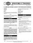
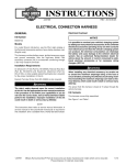
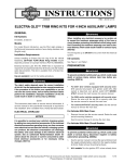
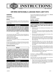
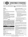
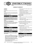
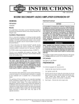
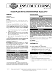
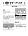
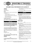
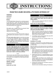
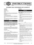
-J05871
REV. 2014-11-13
ILLUMINATED WINDSHIELD TRIM
GENERAL
Kit Number
57000394, 57000395
Models
For model fitment information, see the P&A Retail Catalog or
the Parts and Accessories section of www.harley-davidson.com
(English only).
NOTES
When installing any electrical accessory, be certain not
to exceed the maximum amperage rating of the fuse or
circuit breaker protecting the affected circuit being modified. Exceeding the maximum amperage can lead to electrical failures, which could result in death or serious injury.
(00310a)
The illuminated windshield trim requires up to 260 mA additional current from the electrical system.
The illuminated windshield trim is not intended to replace the
stock turn signals. The illuminated windshield trim will not
function properly without the stock turn signals installed.
Kit Contents
Tools and Supplies Required
INSTALLATION
See Figure 5 and Table 1.
Preparation
The rider's safety depends upon the correct installation
of this kit. Use the appropriate service manual procedures.
If the procedure is not within your capabilities or you do
not have the correct tools, have a Harley-Davidson dealer
perform the installation. Improper installation of this kit
could result in death or serious injury. (00333a)
NOTE
This instruction sheet refers to service manual information. A
service manual for this year/model motorcycle is required for
this installation and is available from a Harley-Davidson dealer.
Electrical Overload
To prevent accidental vehicle start-up, which could cause
death or serious injury, remove main fuse before proceeding. (00251b)
1.
Install Module Harness
1.
-J05871
See the service manual. Remove outer fairing.
NOTE
An example of the module harness routing is shown in Figure
1.The configuration of the inner fairing components can require
a different routing.
2.
It is possible to overload your vehicle's charging system
by adding too many electrical accessories. If the combined
electrical accessories operating at any one time consume
more electrical current than the vehicle's charging system
can produce, the electrical consumption can discharge
the battery and cause damage to the vehicle's electrical
system. See an authorized Harley-Davidson dealer for
advice about the amount of current consumed by additional electrical accessories or for necessary wiring
changes. (00211c)
See the service manual. Remove main fuse.
Route the module harness similarly to the routing shown
in Figure 1. When finished, the routing should:
a.
Secure harness module (3) to harness connector or
other feature with a cable strap (8).
b.
Route the left side turn signal Y-harness (4) (one wire)
to the left side fairing thru-hole to gain access to the
turn signal bracket location.
c.
Route the right side turn signal Y-harness (5) (three
wire) to the right side thru-hole to gain access to the
turn signal bracket location.
d.
Route windshield trim connector (2) to the area of the
right side windshield mounting location.
e.
Secure all harness wiring to existing harnesses with
cable straps (8).
f.
Make sure that wiring is not be pinched, damaged or
otherwise interferes with the installation of the outer
fairing.
Many Harley-Davidson® Parts & Accessories are made of plastics and metals which can be recycled.
Please dispose of materials responsibly.
1 of 4
is08518
1
2
3
8
8
5
4
7
6
1.
2.
3.
4.
Windshield trim connector
Module harness trim connector
Module
Left side turn signal Y-harness
5.
6.
7.
8.
right side turn signal Y-harness
Right side turn signal connector [31R]
Left side turn signal connector [31L]
Cable strap (6)
Figure 1. Module Harness Routing Example
the drilled hole slightly towards the bottom of the hole.
Enlarging the hole will allow the windshield trim wiring to
pass by the threaded mounting insert.
Connect Module Harness to Turn Signals
1.
See the service manual. Remove right turn signal bracket
assembly.
2.
See Figure 2. Locate and disconnect turn signal connector
(2) from turn signal harness connector [31L or 31R](1).
3.
Install the right side turn signal Y-harness(3) to the right
side turn signal harness connector.
4.
See the service manual. Connect the turn signal connector
(2) to the right side turn signal Y-harness.
5.
6.
2.
See Figure 4. Route the connector and wiring (1) through
the enlarged hole (2) in the outer fairing. Install the illuminated windshield trim onto the front of the outer fairing. Hold
trim in place on outer fairing.
3.
See Figure 4. Secure the wiring (1) to the inside of the
outer fairing with tape (3). This allows the wiring to pass
by the threaded mounting insert on the inner fairing without
interference when the outer fairing is installed.
See the service manual. Install turn signal bracket
assembly.
4.
See Figure 1. Connect windshield trim connector (1) to
the module harness trim connector (2).
Repeat the procedure for the opposite side front turn
signal.
5.
See the service manual, Figure 3 and Figure 5. Install
outer fairing. Use the screws (4 and 5) and washers (3)
from the kit to secure the illuminated windshield trim while
installing the windshield.
Install Illuminated Windshield Trim
NOTE
For best results use a stepped drill bit to slowly enlarge the
size of the hole.
1.
See Figure 3. Using a 9/16 inch (14.5 mm) drill bit, enlarge
the right side windshield mounting hole. If possible, offset
-J05871
FINAL ASSEMBLY
1.
Secure all wiring away from any moving parts, pinch points
or extreme heat.
2 of 4
NOTE
Verify that the ignition/light key switch is in the OFF position
before installing the main fuse/attaching the battery cables.
2.
See the service manual. Install main fuse.
3.
Turn the key switch to IGNITION, but do not start the
motorcycle. Test for proper turn signal and illuminated
windshield trim operation.
is08521
2
4
Proper operation of mirror cover lamps is:
a.
Illuminated windshield trim operate as running lights
during normal vehicle operation.
b.
Illuminated windshield trim outer lamps flash with the
corresponding turn signal when activated.
c.
BOTH illuminated windshield trim outer lamps flash
when the emergency flashers are activated.
1
3
6
5
3
4
is08522
3
1
1.
2.
3.
4.
5.
6.
Right side windshield mounting hole
Illuminated windshield trim
Washer (3)
Short screw (2)
Long screw
Connector
Figure 3. Install Illuminated Windshield Trim
2
is08528
2
1
3
1. Turn signal harness connector, female
2. Turn signal connector, male
3. Right side turn signal Y-harness
Figure 2. Auxiliary/Fog Lamp Assembly
1. Wiring
2. Hole
3. Tape
Figure 4. Route Illuminated Windshield Trim Wiring
-J05871
3 of 4
SERVICE PARTS
is08519
1
3
6
4
2
5
3
3
4
Figure 5. Service Parts: Illuminated Windshield Trim
Table 1. Service Parts Table
Item
Description (Quantity)
Part Number
1
Module harness
69201037
2
Illuminated windshield trim
Not Sold Separately
3
Washer (3)
10300087
4
Short screw (2)
4976
5
Long screw
10500034
6
Cable strap (6)
10006
-J05871
4 of 4